-
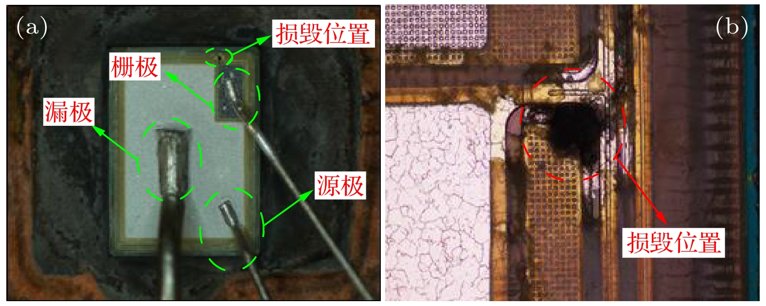
In this paper, failure mechanism of DT 4H-SiC power MOSFET under unclamped inductive switch (UIS) test is evaluated by combination of experiment and theoretical research. The results show that unlike planar 4H-SiC power MOSFET, the gate oxide at the corner of of gate trench is destroyed under the UIS test, therefore, the device under test failed. And then, measurement results of the gate leakage and resistance between gate and source (Rgs) of the failed device indicate that gate leakage increases sharply and Rgs is only 25 Ω, however, the threshold voltage of failure device is unchanged. The analysis of the inner electrical field under avalanche state by using the TCAD software shows that the maximum electrical field exists at the corner of gate trench and the maximum junction temperature does not exceed the melt point of metal. These results are consistent with the experimental results .
-
Keywords:
- 4H-SiC DT power mosfet /
- avalanche energy /
- failure mechanism /
- oxide crack at corner of gate trench
[1] She X, Lucia O, Ozpineci B 2017 IEEE Trans. Ind. Electron. 64 8193
 Google Scholar
[2] Huang A Q 2016 IEEE International Electron Devices Meeting (IEDM), San Francisco, CA, USA, December 2–6, 2016 p528
[3] Kumar A, Parashar S, Baliga J, Bhattacharya S 2018 IEEE Applied Power Electronics Conference and Exposition (APEC), San Antonio, TX, USA, May 1–3, 2008 p2737
[4] Kumar A, Kokkonda R K, Bhattacharya S, Veliadis V 2019 IEEE 7th Workshop on Wide Bandgap Power Devices and Applications (WiPDA), Raleigh, NC, USA, 29–31 October, 2019 p438
[5] Sundaresan S, Mulpuri V, Jeliazkov S, Singh R 2019 IEEE International Reliability Physics Symposium (IRPS), Monterey, CA, USA, March 4–6, 2019 p1
[6] Gao Z, Cao L, Guo Q, Sheng K 2020 IEEE Applied Power Electronics Conference and Exposition (APEC), New Orleans, LA, USA, April 1–3, 2020 p2601
[7] Ren N, Hu H, Wang K L, Zuo Z, Li R, Sheng K 2018 IEEE 30th International Symposium on Power Semiconductor Devices and ICs (ISPSD) Chicago, USA, May 13–17, 2018 p431
[8] Yao K, Yano H, Iwamuro N 2021 33rd International Symposium on Power Semiconductor Devices and ICs (ISPSD) June 2–5, 2021 p115
[9] Wei J X, Liu S Y, Zhao H B, Fu H, Zhang X B, Li S Y, Sun W F 2021 IEEE Trans. Emerg. Sel. Topics Power Electron. 9 2190
 Google Scholar
[10] Li X, Tong X, Hu R, Wen Y, Zhu H, Deng X C, Sun Y K, Chen WJ, Bai S, Zhang B 2021 IEEE Trans. Emerg. Sel. Topics Power Electron. 9 2147
 Google Scholar
[11] Hatakeyama T, Fukuda K, Okumura H, 2013 IEEE T. on Electron Dev. 60 613
 Google Scholar
[12] https://fscdn.rohm.com/en/products/databook/datasheet/discrete/sic/mosfet/sct3080kr-e.pdf
-
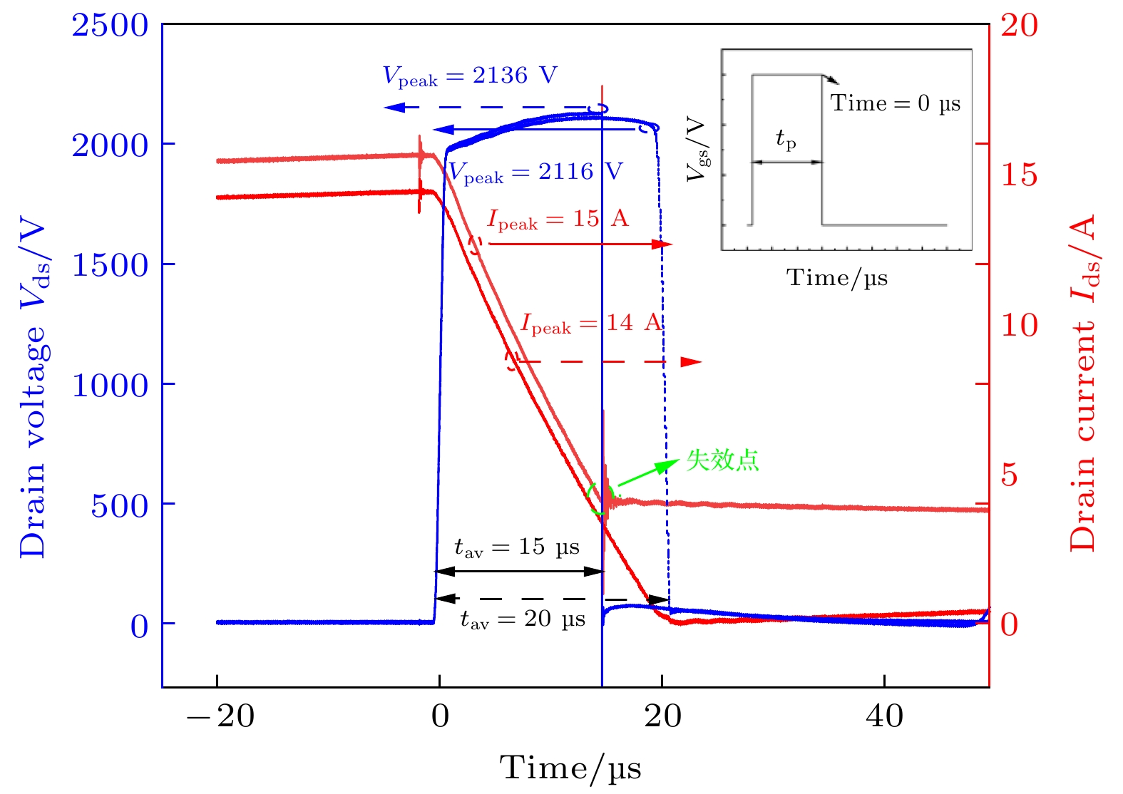
图 2 单脉冲 UIS 测试失效前最后一次实验波形 (划线)(
$ {L}_{\mathrm{l}\mathrm{o}\mathrm{a}\mathrm{d}} $ = 3.3 mH,$ {t}_{\mathrm{a}\mathrm{v}} $ = 20 μs,$ {E}_{\mathrm{a}\mathrm{v}} $ = 0.33 J)与单脉冲 UIS 测试失效实验波形(实线)($ {L}_{\mathrm{l}\mathrm{o}\mathrm{a}\mathrm{d}} $ = 3.3 mH,$ {t}_{\mathrm{a}\mathrm{v}} $ = 15 μs,$ {E}_{\mathrm{a}\mathrm{v}} $ = 0.37 J)Figure 2. Experimental waveforms before failure under single UIS test(solid waveform) (
$ {L}_{\mathrm{l}\mathrm{o}\mathrm{a}\mathrm{d}} $ = 3.3 mH,$ {t}_{\mathrm{a}\mathrm{v}} $ = 20 μs,$ {E}_{\mathrm{a}\mathrm{v}} $ = 0.33 J); experimental waveforms during failure under single UIS test (lineation waveform)($ {L}_{\mathrm{l}\mathrm{o}\mathrm{a}\mathrm{d}} $ = 3.3 mH,$ {t}_{\mathrm{a}\mathrm{v}} $ = 15 μs,$ {E}_{\mathrm{a}\mathrm{v}} $ = 0.37 J).图 4 4H-SiC 功率MOS器件栅泄漏电流和阈值电压变化随
$ {E}_{\mathrm{a}\mathrm{v}} $ 变化 (a) 4H-SiC 功率MOS器件栅泄漏电流随$ {E}_{\mathrm{a}\mathrm{v}} $ 的变化; (b)阈值电压随$ {E}_{\mathrm{a}\mathrm{v}} $ 的变化Figure 4. Gate leakage and
$ {V}_{\mathrm{t}\mathrm{h}} $ of 4H-SiC power MOSFET vs.$ {E}_{\mathrm{a}\mathrm{v}}: $ Gate leakage of 4H-SiC Power MOSFET vs.$\left(\mathrm{b}\right){V}_{\mathrm{t}\mathrm{h}} $ $ \;\mathrm{v}\mathrm{s}.\; {E}_{\mathrm{a}\mathrm{v}}$ 图 10 DUT最大结温随
$ {E}_{\mathrm{a}\mathrm{v}} $ 变化和图9(a)点处器件内部温度分布图 DUT最大结温随$ {E}_{\mathrm{a}\mathrm{v}} $ 变化; (b)图9最大结温a点处器件内部温度分布图Figure 10. Maxium junction temperature vs.
$ {E}_{\mathrm{a}\mathrm{v}} $ and temperature distribution in DUT: (a) Maxium junction temperature; (b) lattice temperature distributionvs.$ {E}_{\mathrm{a}\mathrm{v}} $ of a point in Fig.9. -
[1] She X, Lucia O, Ozpineci B 2017 IEEE Trans. Ind. Electron. 64 8193
 Google Scholar
[2] Huang A Q 2016 IEEE International Electron Devices Meeting (IEDM), San Francisco, CA, USA, December 2–6, 2016 p528
[3] Kumar A, Parashar S, Baliga J, Bhattacharya S 2018 IEEE Applied Power Electronics Conference and Exposition (APEC), San Antonio, TX, USA, May 1–3, 2008 p2737
[4] Kumar A, Kokkonda R K, Bhattacharya S, Veliadis V 2019 IEEE 7th Workshop on Wide Bandgap Power Devices and Applications (WiPDA), Raleigh, NC, USA, 29–31 October, 2019 p438
[5] Sundaresan S, Mulpuri V, Jeliazkov S, Singh R 2019 IEEE International Reliability Physics Symposium (IRPS), Monterey, CA, USA, March 4–6, 2019 p1
[6] Gao Z, Cao L, Guo Q, Sheng K 2020 IEEE Applied Power Electronics Conference and Exposition (APEC), New Orleans, LA, USA, April 1–3, 2020 p2601
[7] Ren N, Hu H, Wang K L, Zuo Z, Li R, Sheng K 2018 IEEE 30th International Symposium on Power Semiconductor Devices and ICs (ISPSD) Chicago, USA, May 13–17, 2018 p431
[8] Yao K, Yano H, Iwamuro N 2021 33rd International Symposium on Power Semiconductor Devices and ICs (ISPSD) June 2–5, 2021 p115
[9] Wei J X, Liu S Y, Zhao H B, Fu H, Zhang X B, Li S Y, Sun W F 2021 IEEE Trans. Emerg. Sel. Topics Power Electron. 9 2190
 Google Scholar
[10] Li X, Tong X, Hu R, Wen Y, Zhu H, Deng X C, Sun Y K, Chen WJ, Bai S, Zhang B 2021 IEEE Trans. Emerg. Sel. Topics Power Electron. 9 2147
 Google Scholar
[11] Hatakeyama T, Fukuda K, Okumura H, 2013 IEEE T. on Electron Dev. 60 613
 Google Scholar
[12] https://fscdn.rohm.com/en/products/databook/datasheet/discrete/sic/mosfet/sct3080kr-e.pdf
Catalog
Metrics
- Abstract views: 8359
- PDF Downloads: 188
- Cited By: 0


 DownLoad:


