


-
Magnetic refrigeration has become a promising new technology to replace conventional vapor-compression refrigeration technology, for it has excellent application characteristics such as the high efficiency, environmental friendliness and structural simplicity. Many studies have been carried out to analyze the various subsystems, but the interaction laws between the systems are not yet clear, and the optimization of each subsystem is still an area of research worth exploring. This work is based on a compact room temperature magnetic refrigeration system developed before, and carries out experimental research on the different flow time ratio to explore the correlation among refrigeration temperature span, cooling capacity, pressure drop, coefficient of performance (COP) and blow fraction under a fixed magnetic field timing. Especially, the effects of different flow time ratios (100%, 80%, 60%) on the system performance are studied under magnetic field timing of 1∶4∶1∶4 and a frequency of 0.45 Hz. The experimental results reveal that a low utilization factor combined with a high flow time ratio can achieve a greater temperature spread, whereas a high utilization factor combined with a high flow time ratio can accomplish a bigger cooling capacity. When the utilization factor is 0.42 and the flow time ratio is 100%, the maximum unloaded cooling temperature span is 26.2 K. Meanwhile, the effects of the utilization factor and flow time ratio on the pressure drop and COP of the regenerator are studied in detail. It is discovered that raising the flow time ratio and reducing the utilization factor both result in a fall in fluid velocity, which leads the pressure to further decrease and the COP to rise. In a word, this research investigates the relationship among cooling temperature span, cooling capacity, pressure drop, COP, and flow time ratio in a fixed magnetic field timing, thus providing the groundwork for future improving the performances of room temperature magnetic refrigeration systems.
-
Keywords:
- flow time ratio /
- refrigeration temperature span /
- refrigerating capacity /
- coefficient of performance
[1] Franco G, Victorino, Blázquez G, Javier S, Ipus B, Jhon J, Law, Jia Y, Moreno R, Luis M, Conde A, Alejandro 2018 Prog. Mater. Sci. 93 112
 Google Scholar
[2] 李连生 2011 制冷学报 32 53
Google Scholar
Li L S 2011 J. Refrig. 32 53
Google Scholar
[3] 张朝晖, 陈敬良, 高钰, 刘晓红 2015 制冷与空调 15 1
Google Scholar
Zhang Z H, Chen J L, Gao Y, Liu X H 2015 Refrig. Air-Conditioning 15 1
Google Scholar
[4] DiPirro M, Tuttle J, Jackson M, Canavan E, Warner B, Shirron P 2006 AIP Conf. Proc. 823 969
Google Scholar
[5] Warburg E 1881 Ann. Phys. 249 141
Google Scholar
[6] Brown G V 1976 J. Appl. Phys. 47 3673
Google Scholar
[7] Zimm C, Boeder A, Chell J, Sternberg A, Fujita A, Fujieda S, Fukamichi K 2006 Int. J. Refrig. 29 1302
Google Scholar
[8] Jacobs S, Auringer J, Boeder A, Chell J, Komorowski L, Leonard J, Russek S, Zimm C 2014 Int. J. Refrig. 37 84
Google Scholar
[9] Nakashima A T D, Dutra S L, Trevizoli P V, Barbosa J R 2018 Int. J. Refrig. 93 159
Google Scholar
[10] Nakashima A T D, Dutra S L, Trevizoli P V, Barbosa J R 2018 Int. J. Refrig. 93 236
Google Scholar
[11] 李振兴, 李珂, 沈俊, 戴巍, 贾际深, 郭小惠, 高新强, 公孙琼 2017 低温工程 215 13
Li Z X, Li K, Shen J, Dai W, Jia J C, Guo X H, Gao X Q, Gong S M 2017 Cryogenics 215 13
[12] Li Z X, Li K, Guo X H, Gao X Q, Dai W, Gong S M, Shen J 2021 Appl. Therm. Eng. 187 116477
Google Scholar
[13] 于世霖, 赵金良, 李振兴, 海鹏, 李珂, 莫兆军, 高新强, 戴巍, 沈俊 2022 工程 43 3204
Yu S L, Zhao J L, Li Z X, Hai P, Li K, Mo Z J, Gao X Q, Dai W, Shen J 2022 J. Eng. Thermophys. 43 3204
[14] Hai P, Shen J, Li Z X, Li K, Huang H M, Zheng W S, Dai W, Gao X Q, Mo Z J 2023 Appl. Therm. Eng. 219 119561
Google Scholar
[15] Tušek J, Kitanovski A, Zupan S, Prebil I, Poredoš A 2013 Appl. Therm. Eng. 53 57
Google Scholar
[16] Trevizoli P V, Nakashima A T, Peixer G F, Barbosa J R 2017 Appl. Energy 187 847
Google Scholar
[17] Bjørk R, Bahl C R H, Smith A, Christensen D V, Pryds N 2010 J. Magn. Magn. Mater. 322 3324
Google Scholar
[18] Teyber R, Trevizoli P V, Christiaanse T V, Govindappa P, Niknia I, Rowe A 2017 J. Magn. Magn. Mater. 442 87
Google Scholar
[19] Lei T, Engelbrecht K, Nielsen K K, Veje C T 2017 Appl. Therm. Eng. 111 1232
Google Scholar
[20] You Y H, Guo Y, Xiao S F, Yu S, Ji H, Luo X B 2016 J. Magn. Magn. Mater. 405 231
Google Scholar
-

图 1 室温磁制冷系统原理图
Figure 1. Schematic diagram of room temperature magnetic refrigeration system.
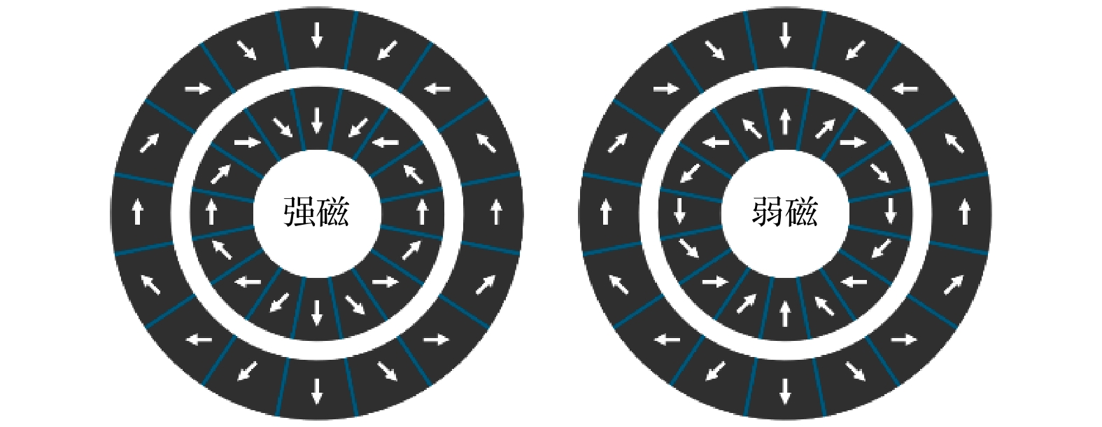
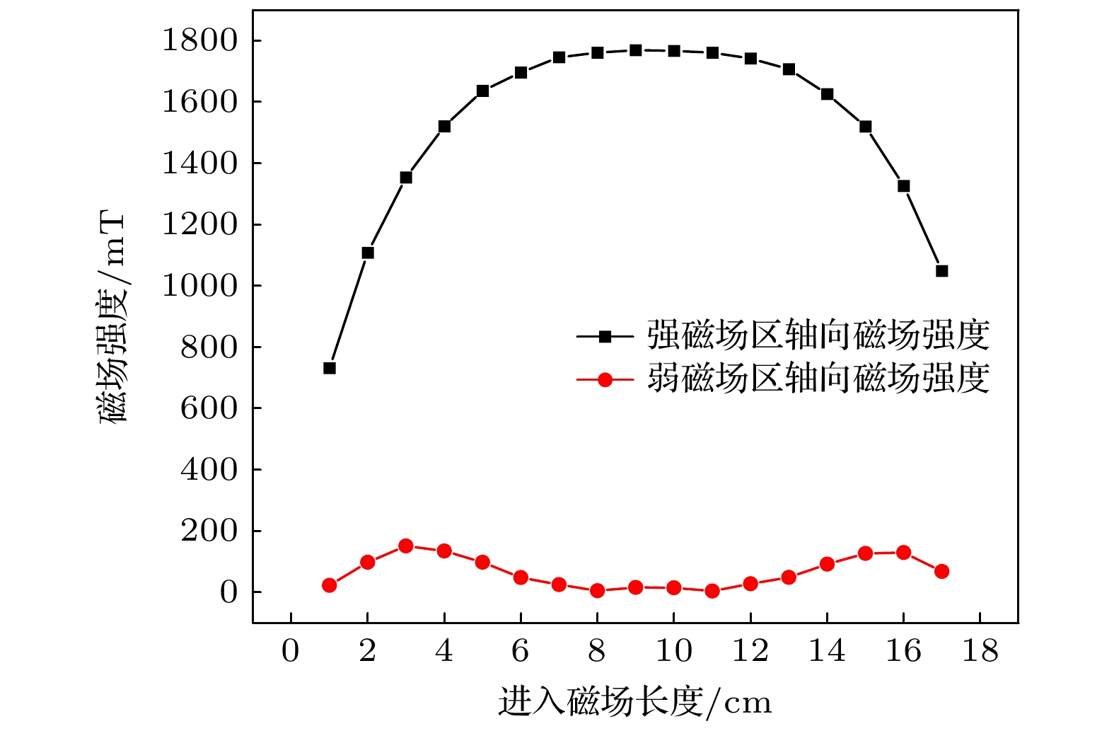
图 3 双层同心Halbach磁体组轴线中心处磁场强度示意图
Figure 3. Schematic diagram of the magnetic field intensity at the center of the axis of the double-layer concentric Halbach magnet group.
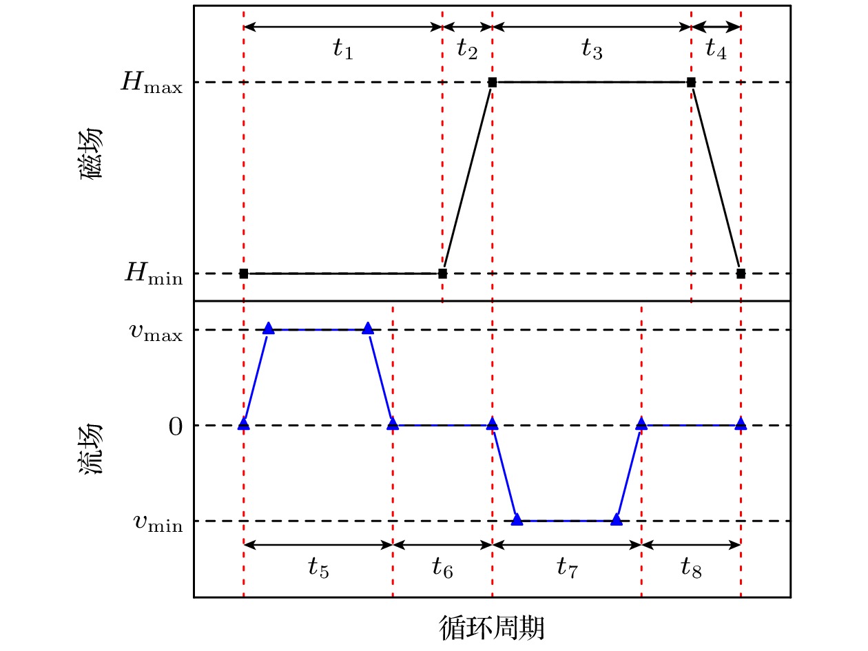
图 4 磁场及流场波形图
Figure 4. Time diagram of magnetic field and fluid flow rate.
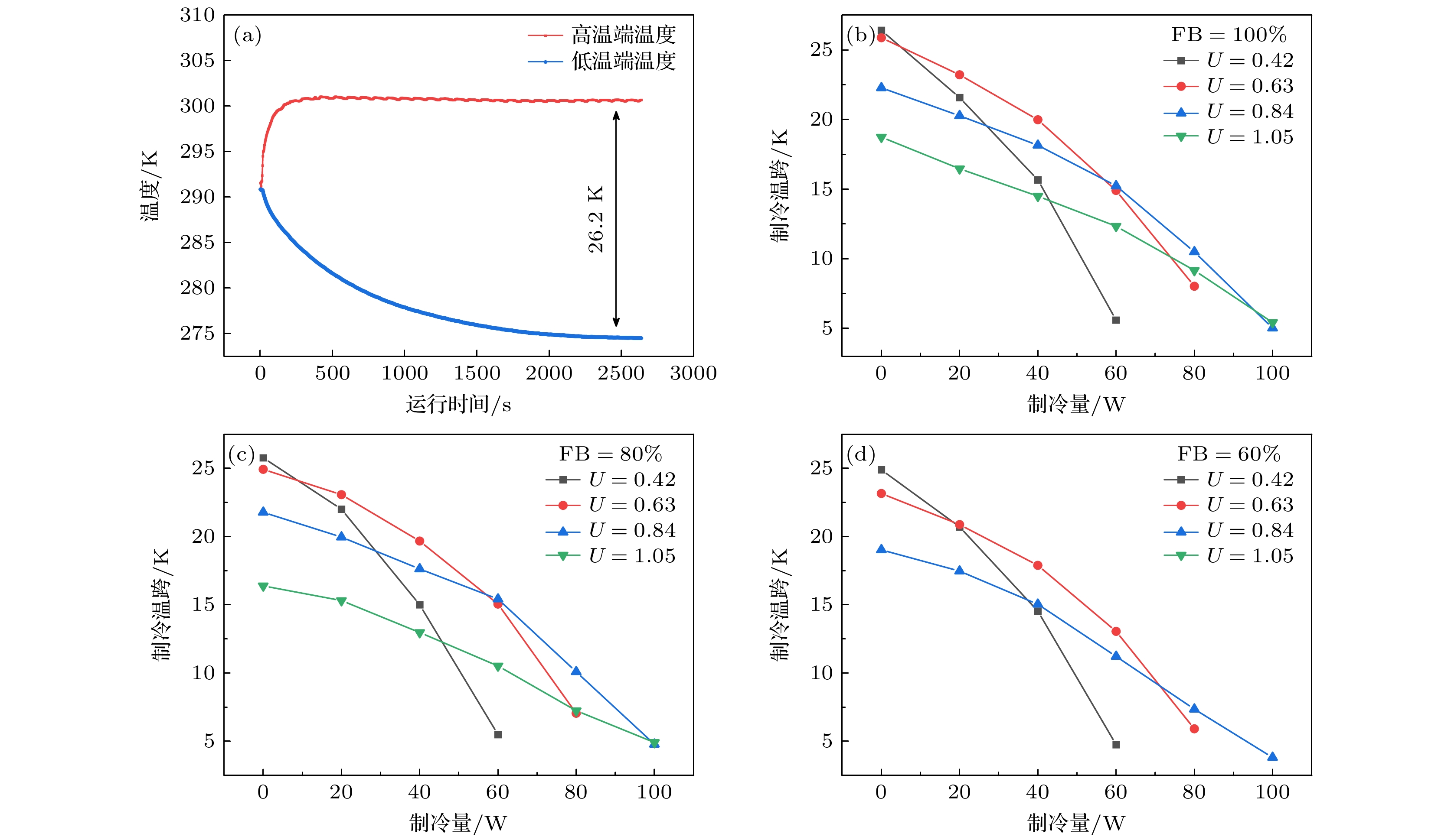
图 5 (a)运行频率0.45 Hz、流动时间占比FB = 100%, 利用系数U = 0.42的工况下整机系统的降温(蓝色)和升温曲线(红色); (b)—(d)分别在FB = 100%, 80%, 60%流动时间占比下, 不同利用系数下制冷温跨随制冷量的变化曲线
Figure 5. (a) Cooling (blue) and heating (red) curves of the entire system under the operating condition with 0.45 Hz, FB = 100%, U = 0.42; (b)–(d) the variation curve of cooling temperature difference with refrigeration capacity under FB = 100%, 80%, 60%.

图 6 三种流动时间占比FB, 无负荷工况下制冷温跨随利用系数的变化曲线
Figure 6. For the three flow time ratios, refrigeration temperature span vs. utilization factor change curve under no-load conditions.
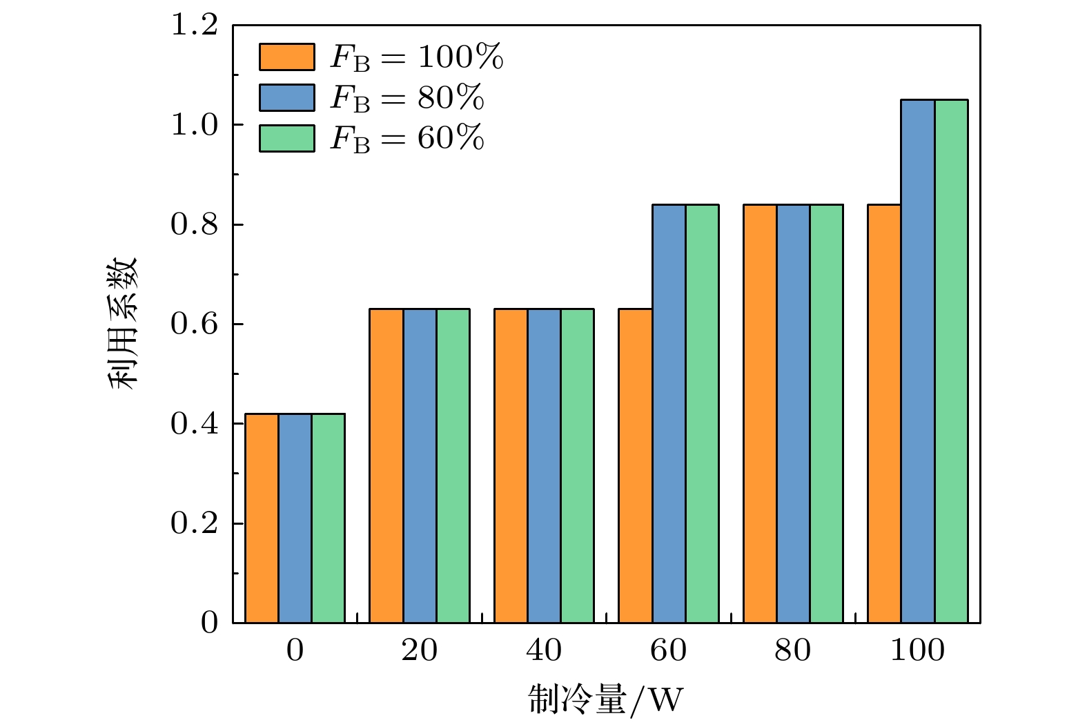
图 7 不同热载荷下, 最大制冷温跨所对应的利用系数
Figure 7. Utilization factor corresponding to the maximum refrigeration temperature span at different heat loads.

图 8 (a)不同流动时间占比下回热器压降与利用系数的关系曲线; (b)不同流动时间占比下COP与利用系数的关系曲线, 插图显示不同流动时间占比下输入电功率与利用系数的关系曲线
Figure 8. (a) Variation curves of pressure drop with utilization factor under different flow time ratios; (b) variation curves of COP with utilization factor under different flow time ratios, the inset figure shows variation curves of input electrical power with utilization factor under different flow time ratios.
-
[1] Franco G, Victorino, Blázquez G, Javier S, Ipus B, Jhon J, Law, Jia Y, Moreno R, Luis M, Conde A, Alejandro 2018 Prog. Mater. Sci. 93 112
Google Scholar
[2] 李连生 2011 制冷学报 32 53
Google Scholar
Li L S 2011 J. Refrig. 32 53
Google Scholar
[3] 张朝晖, 陈敬良, 高钰, 刘晓红 2015 制冷与空调 15 1
Google Scholar
Zhang Z H, Chen J L, Gao Y, Liu X H 2015 Refrig. Air-Conditioning 15 1
Google Scholar
[4] DiPirro M, Tuttle J, Jackson M, Canavan E, Warner B, Shirron P 2006 AIP Conf. Proc. 823 969
Google Scholar
[5] Warburg E 1881 Ann. Phys. 249 141
Google Scholar
[6] Brown G V 1976 J. Appl. Phys. 47 3673
Google Scholar
[7] Zimm C, Boeder A, Chell J, Sternberg A, Fujita A, Fujieda S, Fukamichi K 2006 Int. J. Refrig. 29 1302
Google Scholar
[8] Jacobs S, Auringer J, Boeder A, Chell J, Komorowski L, Leonard J, Russek S, Zimm C 2014 Int. J. Refrig. 37 84
Google Scholar
[9] Nakashima A T D, Dutra S L, Trevizoli P V, Barbosa J R 2018 Int. J. Refrig. 93 159
Google Scholar
[10] Nakashima A T D, Dutra S L, Trevizoli P V, Barbosa J R 2018 Int. J. Refrig. 93 236
Google Scholar
[11] 李振兴, 李珂, 沈俊, 戴巍, 贾际深, 郭小惠, 高新强, 公孙琼 2017 低温工程 215 13
Li Z X, Li K, Shen J, Dai W, Jia J C, Guo X H, Gao X Q, Gong S M 2017 Cryogenics 215 13
[12] Li Z X, Li K, Guo X H, Gao X Q, Dai W, Gong S M, Shen J 2021 Appl. Therm. Eng. 187 116477
Google Scholar
[13] 于世霖, 赵金良, 李振兴, 海鹏, 李珂, 莫兆军, 高新强, 戴巍, 沈俊 2022 工程 43 3204
Yu S L, Zhao J L, Li Z X, Hai P, Li K, Mo Z J, Gao X Q, Dai W, Shen J 2022 J. Eng. Thermophys. 43 3204
[14] Hai P, Shen J, Li Z X, Li K, Huang H M, Zheng W S, Dai W, Gao X Q, Mo Z J 2023 Appl. Therm. Eng. 219 119561
Google Scholar
[15] Tušek J, Kitanovski A, Zupan S, Prebil I, Poredoš A 2013 Appl. Therm. Eng. 53 57
Google Scholar
[16] Trevizoli P V, Nakashima A T, Peixer G F, Barbosa J R 2017 Appl. Energy 187 847
Google Scholar
[17] Bjørk R, Bahl C R H, Smith A, Christensen D V, Pryds N 2010 J. Magn. Magn. Mater. 322 3324
Google Scholar
[18] Teyber R, Trevizoli P V, Christiaanse T V, Govindappa P, Niknia I, Rowe A 2017 J. Magn. Magn. Mater. 442 87
Google Scholar
[19] Lei T, Engelbrecht K, Nielsen K K, Veje C T 2017 Appl. Therm. Eng. 111 1232
Google Scholar
[20] You Y H, Guo Y, Xiao S F, Yu S, Ji H, Luo X B 2016 J. Magn. Magn. Mater. 405 231
Google Scholar


 DownLoad:


Catalog
Metrics
- Abstract views: 5482
- PDF Downloads: 80
- Cited By: 0
