-
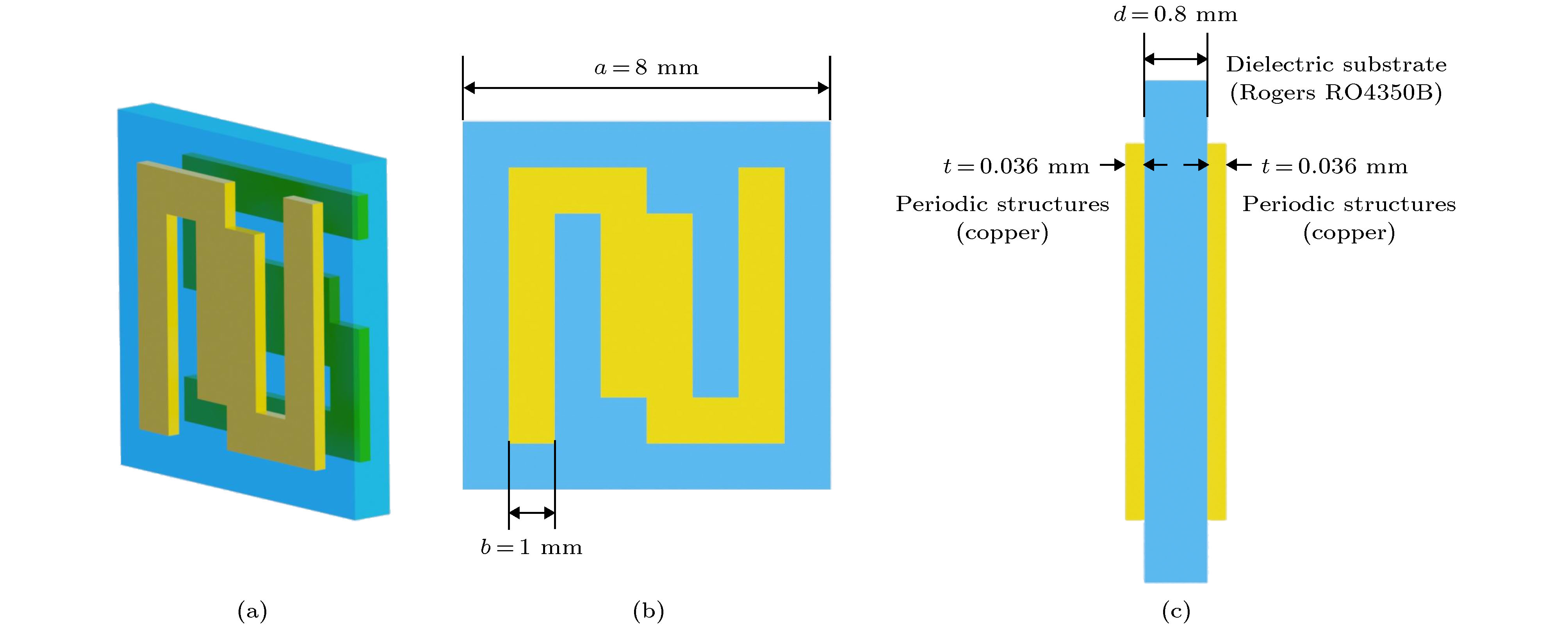
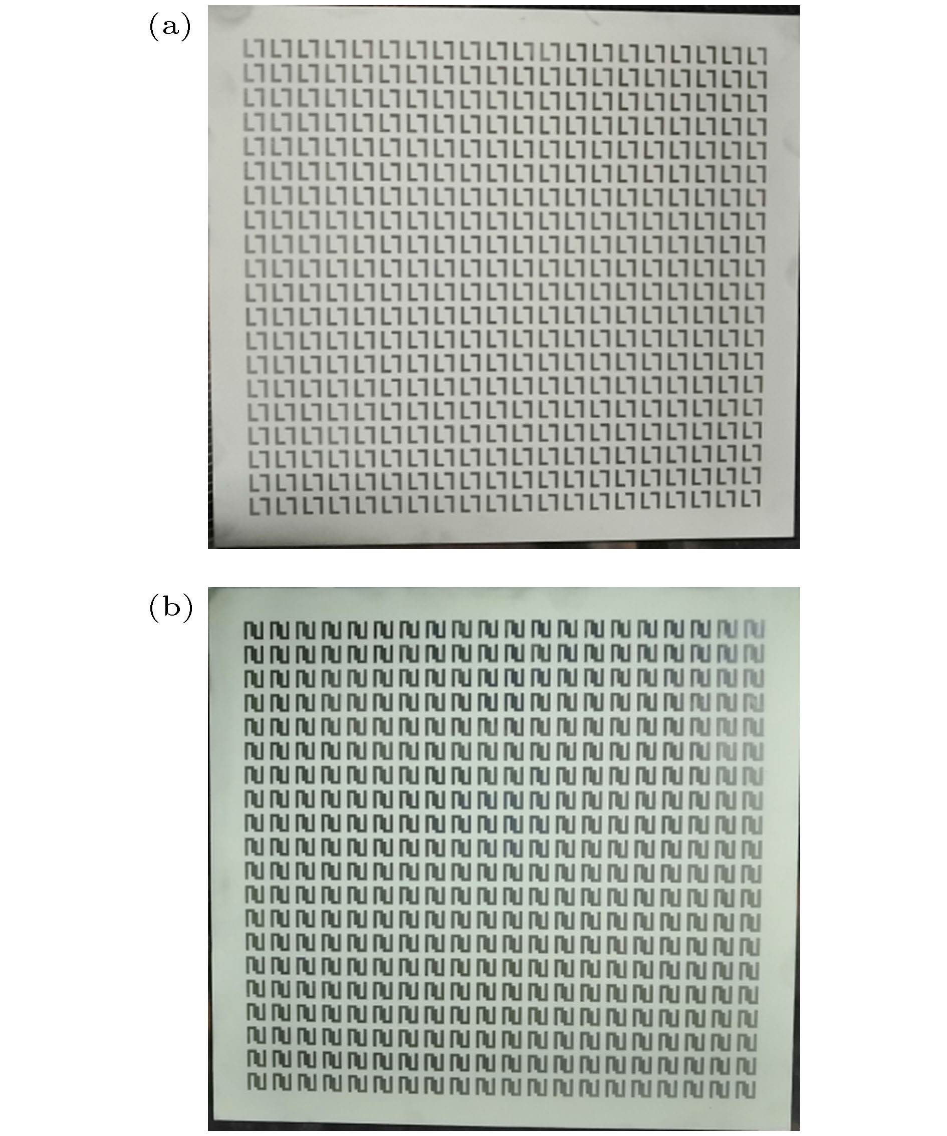
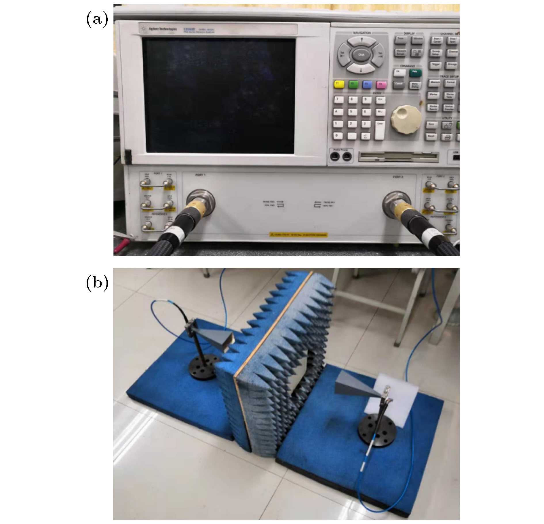
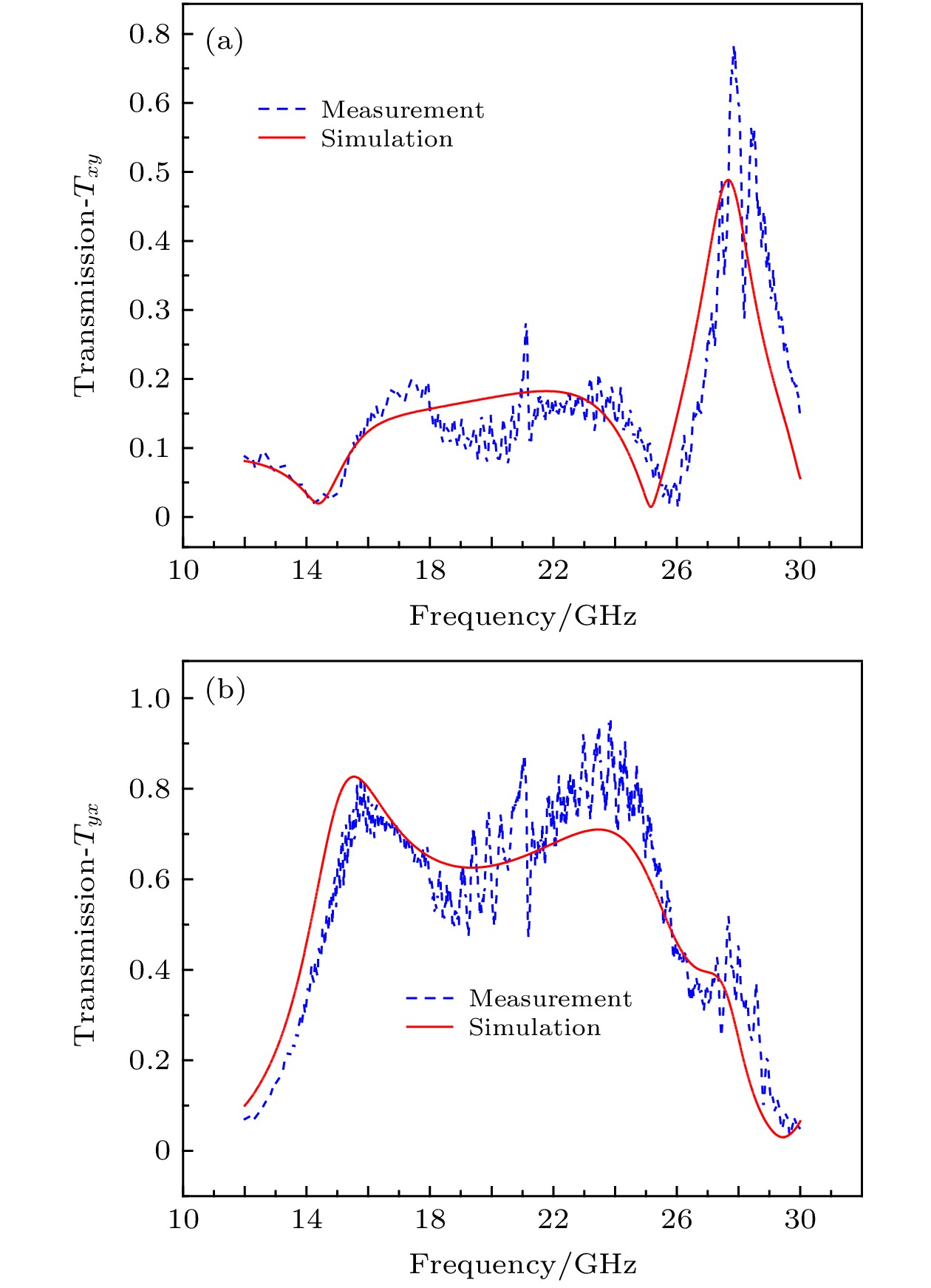
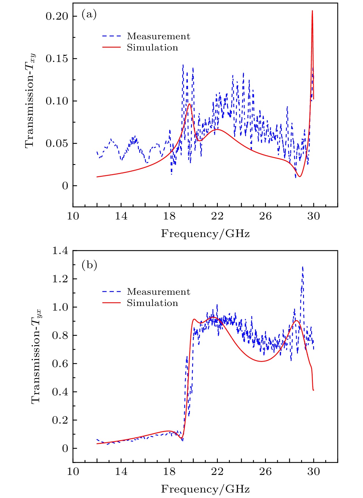
Asymmetric transmission (AT) metamaterials are extensively studied and applied in the fields of polarization converters and photodiodes. In order to further improve the properties of polarization conversion and unidirectional conduction in the high frequency band and to implement their tunability, the novel chiral electromagnetic metamaterials are studied. By the topology optimization technique, a new type of double-layer L-shaped variant metamaterial structure with excellent asymmetric transmission characteristics is designed. The objective function is to maximize the asymmetric transmission coefficient for the linear polarization wave. The rotationally symmetrical design domain is determined by considering polarization conversion and computation efficiency simultaneously. The design domain of upper layer is divided into two parts which are both the 180° rotationally symmetrical. The design domain of the upper layer and lower layer are the 90° rotationally symmetrical around the x and z axis respectively. Therefore, the number of design variables is only 18. Asymmetric transmission of linear polarization wave in the K band and Ka band are implemented. Numerical simulation results and experimental results show that the optimized chiral metamaterial has excellent asymmetric transmission characteristics, and its asymmetric transmission coefficient reaches 0.8562 at a frequency of 21.65 GHz and 0.8175 at a frequency of 28.575 GHz. Its asymmetric transmission mechanism is expounded by analyzing the electric field and surface current distribution at the resonance frequency. Based on the optimized chiral metamatertials, the reasonable geometric parameters are selected and the rotation angle of the metal layer is changed in order to further achieve the tunable AT characteristics. First, the influences of the dielectric substrate layer, the thickness of the metal layer and the side length of the grid on resonance frequency and asymmetric transmission coefficient are analyzed respectively, which provides the basis for the reasonable adjustment of the structural parameters to obtain better asymmetric transmission characteristics. After the reasonable geometric parameters are determined, the rotational angle of the upper metal layer and lower metal layer are changed. The linearly and circularly polarized wave are simultaneously achieved in the K band. In this article, the topology optimization technique is used to design the asymmetric transmission chiral metamaterial structure. The design process has a clear direction. The optimized asymmetric transmission chiral metamaterial has the simple structure type and the easy tunability of its asymmetric transmission characteristics. It can be used widely and easily in the fields of polarization converters and photodiodes. This design method has a broad application prospect in the chiral metamaterial field.
-
Keywords:
- asymmetric transmission /
- tunablity /
- chiral metamaterials /
- topology optimization
[1] 徐进, 李荣强, 蒋小平, 王身云, 韩天成 2019 68 117801
 Google Scholar
Xu J, Li R Q, Jiang X P, Wang S Y, Han T C 2019 Acta Phys. Sin. 68 117801
 Google Scholar
[2] 金柯, 刘永强, 韩俊, 杨崇民, 王颖辉, 王慧娜 2017 66 134201
 Google Scholar
Jin K, Liu Y Q, Han J, Yang C M, Wang Y H, Wang H N 2017 Acta Phys. Sin. 66 134201
 Google Scholar
[3] Silva A, Monticone F, Castaldi G, Galdi V, Alu A, Engheta N 2014 Science 343 6167
 Google Scholar
[4] Veselago V G 1968 Sov. Phys. Usp. 10 509
 Google Scholar
[5] Shelby R A, Smith D R, Schultz S 2001 Science 292 5514
 Google Scholar
[6] Smith D R, Padilla W J, Vier D C, Nasser N, Schultz S 2000 Phys. Rev. Let. 84 4184
 Google Scholar
[7] Pendry J B, Holden A J, Stewart W J, Youngs I 1996 Phys. Rev. Let. 76 4773
 Google Scholar
[8] Pendry J B, Holden A J, Robbins D J, Stewart W J, Member 1999 IEEE Trans. on Microw. Theory. 47 2075
 Google Scholar
[9] Caloz C, Itoh T 2004 IEEE Microw. Mag. 5 34
 Google Scholar
[10] Liu D Y, Yao L F, Zhai X M, Li M H, Dong J F 2014 Appl. Phys. A 116 9
 Google Scholar
[11] Yang Y, Wang W, Moitra P, Kravchenko I I, Briggs D P, Valentine J 2014 Nano Lett. 14 1394
 Google Scholar
[12] Baena J D, Tisco J P, Slobozhanyuk A P, Glybovski S B, Belov P A 2015 Phys. Rev. B 92 245413
 Google Scholar
[13] Landy N I, Sajuyigbe S, Mock J J, Smith D R, Padilla W J 2008 Phys. Rev. Let. 100 207402
 Google Scholar
[14] Yu N, Aieta F, Genevet P, Kats M A, Gaburro Z, Capasso F 2012 Nano Lett. 12 6328
 Google Scholar
[15] Pendry J B 2000 Phys. Rev. Let. 85 3966
 Google Scholar
[16] Schurig D, Mock J J, Justice B J, Cummer S A, Pendry J B, Starr A F, Smith D R 2006 Science 314 5801
 Google Scholar
[17] Ganesel J K, Thiel M, Rill M S, Decker M, Bade K, Saile V, Freymann G, Linden S, Wegener M 2009 Science 325 1513
 Google Scholar
[18] Tretyakov S, Nefedov I, Sihvola A, Maslovski S, Simovski C 2003 J. Electromagnet. Wave. 17 695
 Google Scholar
[19] Fedotov V A, Mladyonov P L, Prosvirnin S L, Rogacheva A V, Chen Y, Zheludev N I 2006 Phys. Rev. Let. 97 167401
 Google Scholar
[20] Fedotov V A, Schwanecke A S, Zheludev N I, Khardikov V V, Prosvirnin S L 2007 Nano Lett. 7 1996
 Google Scholar
[21] Menzel C, Helgert C, Rockstuhl C, Kley E B, Tünnermann A, Pertsch T, Lederer F 2010 Phys. Rev. Let. 104 253902
 Google Scholar
[22] Mutlu M, Akosman A E, Serebryannikov A E, Ozbay E 2012 Phys. Rev. Let. 108 213905
 Google Scholar
[23] Singh R, Plum E, Menzel C, et al. 2009 Phys. Rev. B 80 153104
 Google Scholar
[24] Plum E, Fedotov V A, Zheludev N I 2011 J. Opt. 13 024006
[25] Shi J H, Liu X C, Yu S, Lv T T, Zhu Z, Ma H F, Cui T J 2013 Appl. Phys. Let 102 191905
 Google Scholar
[26] Wu L X, Zhang M, Zhu B, Zhao J M, Jiang T, Feng Y J 2014 Appl. Phys. B 117 527
[27] Stephen L, Yogesh N, Subramanian V 2018 J. Appl. Phys. 123 033103
 Google Scholar
[28] Ji W, Cai T, Wang B, Wang G G, Li H P, Wang C Y, Hou H S, Zhang C B 2019 Opt. Express 27 2844
 Google Scholar
[29] Liu W B, Wu W, Huang L R, Ling Y H, Ba C F, Li S, Chun Z H, Li H H 2019 Opt. Express 27 33399
 Google Scholar
[30] Song Q H, Wu P C, Zhu W M, et al. 2019 Appl. Phys. Let. 114 151105
 Google Scholar
[31] Liu M, Xu Q, Chen X Y, et al. 2019 Sci. Rep. 9 4097
 Google Scholar
[32] Zhao J X, Song J L, Xu T Y, Yang T X, Zhou J H 2019 Opt. Express 27 9773
 Google Scholar
[33] Dai L L, Zhang Y P, F. O’Hara J, Zhang H Y 2019 Opt. Express 27 35784
 Google Scholar
[34] Novitsky A V, Galynsky V M, Zhukovsky S V 2012 Phys. Rev. B 86 075138
 Google Scholar
[35] Mühlig S, Menzel C, Rockstuhl C, Lederer F 2011 Met. Mater. 5 64
[36] Mirzamohammadi F, Nourinia J, Ghobadi C, Majidzadeh M 2019 Int. J. Electron. Commun. (AEÜ) 98 58
 Google Scholar
[37] Liu D J, Xiao Z Y, Ma X L, Ma Q W, Xu X X, Wang Z H 2015 Opt. Commun. 338 359
-
图 5 (a)初始结构非对称传输系数
$ {\varDelta }_{\mathrm{l}\mathrm{i}\mathrm{n}}^{x}/{\varDelta }_{\mathrm{l}\mathrm{i}\mathrm{n}}^{y} $ ; (b)优化结构非对称传输系数$ {\varDelta }_{\mathrm{l}\mathrm{i}\mathrm{n}}^{x}/{\varDelta }_{\mathrm{l}\mathrm{i}\mathrm{n}}^{y} $ Figure 5. (a) Asymmetric transmission coefficient of initial structure
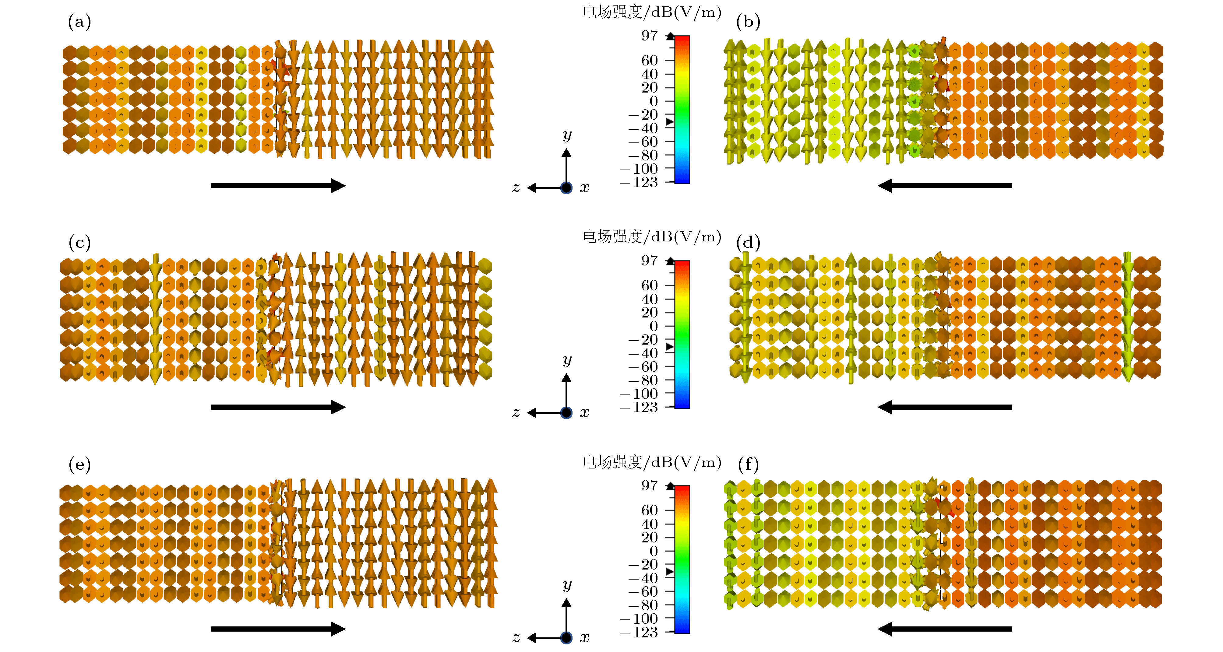
$ {\varDelta }_{\mathrm{l}\mathrm{i}\mathrm{n}}^{x}/{\varDelta }_{\mathrm{l}\mathrm{i}\mathrm{n}}^{y} $ ; (b) asymmetric transmission coefficient of optimized structure$ {\varDelta }_{\mathrm{l}\mathrm{i}\mathrm{n}}^{x}/{\varDelta }_{\mathrm{l}\mathrm{i}\mathrm{n}}^{y} $ .图 13 线性x极化波沿–z及+z方向入射时优化结构两侧电场分布 (a), (b) f = 20.075 GHz; (c), (d) f = 21.65 GHz; (e), (f) f = 28.575 GHz
Figure 13. Electrical field distributions on both sides of the optimized structure when the linear x-polarized wave is incident along the –z and +z directions: (a), (b) f = 20.075 GHz; (c), (d) f = 21.65 GHz; (e), (f) f = 28.575 GHz
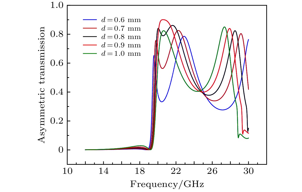
图 14 线性x极化波沿–z方向入射时优化结构介质层厚度d对非对称传输系数
$ {\varDelta }_{\mathrm{l}\mathrm{i}\mathrm{n}}^{x} $ 的影响Figure 14. Effect of the thickness d of dielectric layer on the asymmetric transmission coefficient
$ {\varDelta }_{\mathrm{l}\mathrm{i}\mathrm{n}}^{x} $ when linear x-polarized wave is incident in the –z direction.图 15 线性x极化波沿–z方向入射时优化结构金属层厚度t对非对称传输系数
$ {\varDelta }_{\mathrm{l}\mathrm{i}\mathrm{n}}^{x} $ 影响Figure 15. Effect of the thickness t of the optimized structural metal layer on the asymmetric transmission coefficient
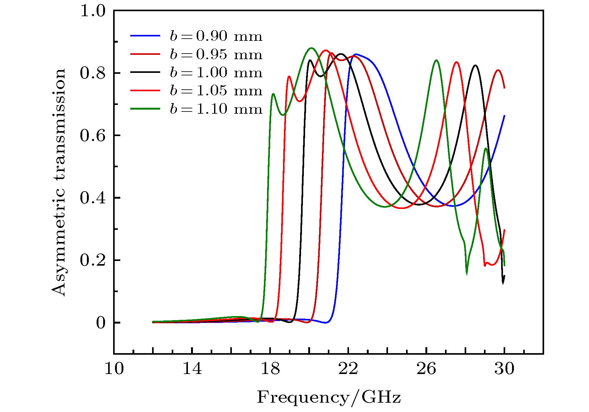
$ {\varDelta }_{\mathrm{l}\mathrm{i}\mathrm{n}}^{x} $ when the linear x-polarized wave is incident in the–z direction.图 16 线性x极化波沿–z方向入射时优化结构网格边长b对非对称传输系数
$ {\varDelta }_{\mathrm{l}\mathrm{i}\mathrm{n}}^{x} $ 影响Figure 16. Effect of the small square side length b on the asymmetric transmission coefficient
$ {\varDelta }_{\mathrm{l}\mathrm{i}\mathrm{n}}^{x} $ when the linear x-polarized wave is incident in the –z direction.图 18 线性x极化波沿–z方向入射时底层金属旋转角度对非对称传输系数
$ {\varDelta }_{\mathrm{l}\mathrm{i}\mathrm{n}}^{x} $ 影响Figure 18. Influence of the rotation angle of the underlying metal on the asymmetric transmission coefficient
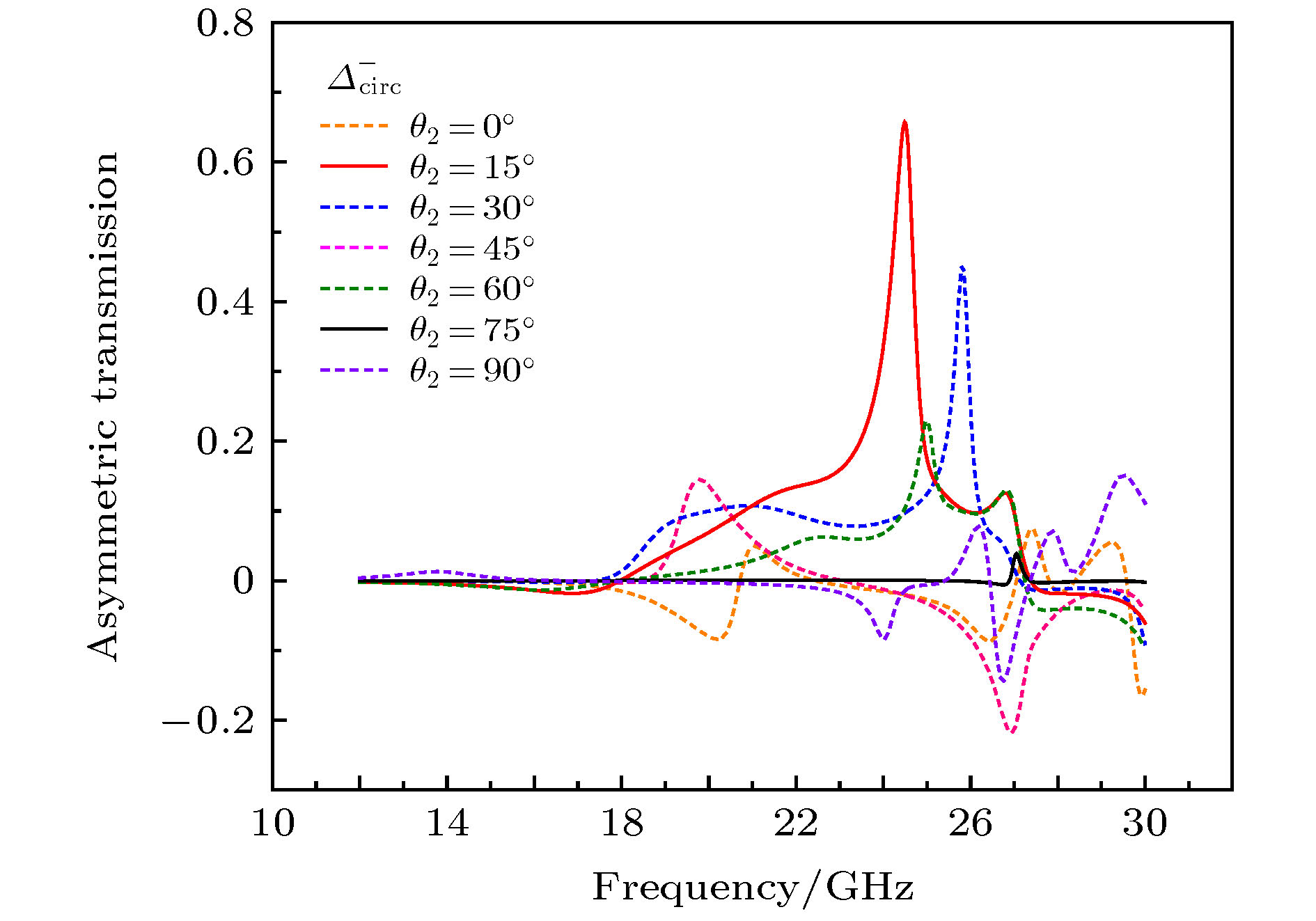
$ {\varDelta }_{\mathrm{l}\mathrm{i}\mathrm{n}}^{x} $ when the linear x-polarized wave is incident in the –z direction.图 19 圆极化波沿–z方向入射时底层金属旋转角度对非对称传输系数
$ {\varDelta }_{\mathrm{c}\mathrm{i}\mathrm{r}\mathrm{c}}^{-} $ 影响Figure 19. Influence of the rotation angle of the underlying metal on the asymmetric transmission coefficient
$ {\varDelta }_{\mathrm{c}\mathrm{i}\mathrm{r}\mathrm{c}}^{-} $ when a circularly polarized wave is incident in the –z direction.图 20 (a)线性极化波非对称传输系数
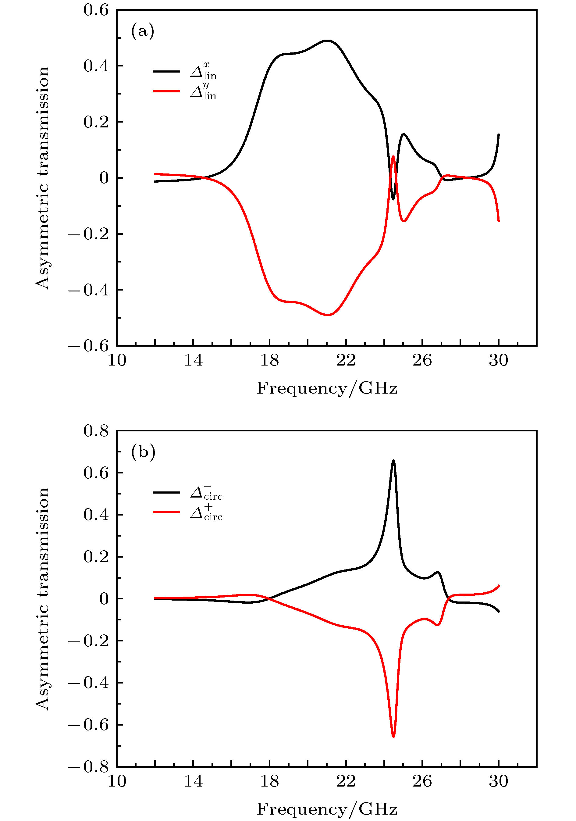
$ {\varDelta }_{\mathrm{l}\mathrm{i}\mathrm{n}}^{x}/{\varDelta }_{\mathrm{l}\mathrm{i}\mathrm{n}}^{y} $ ; (b)圆极化波非对称传输系数$ {\varDelta }_{\mathrm{c}\mathrm{i}\mathrm{r}\mathrm{c}}^{+}/{\varDelta }_{\mathrm{c}\mathrm{i}\mathrm{r}\mathrm{c}}^{-} $ Figure 20. (a) Asymmetric transmission coefficient of linearly polarized wave
$ {\varDelta }_{\mathrm{l}\mathrm{i}\mathrm{n}}^{x}/{\varDelta }_{\mathrm{l}\mathrm{i}\mathrm{n}}^{y} $ ; (b) asymmetric transmission coefficient of circularly polarized wave$ {\varDelta }_{\mathrm{c}\mathrm{i}\mathrm{r}\mathrm{c}}^{+}/{\varDelta }_{\mathrm{c}\mathrm{i}\mathrm{r}\mathrm{c}}^{-} $ . -
[1] 徐进, 李荣强, 蒋小平, 王身云, 韩天成 2019 68 117801
 Google Scholar
Xu J, Li R Q, Jiang X P, Wang S Y, Han T C 2019 Acta Phys. Sin. 68 117801
 Google Scholar
[2] 金柯, 刘永强, 韩俊, 杨崇民, 王颖辉, 王慧娜 2017 66 134201
 Google Scholar
Jin K, Liu Y Q, Han J, Yang C M, Wang Y H, Wang H N 2017 Acta Phys. Sin. 66 134201
 Google Scholar
[3] Silva A, Monticone F, Castaldi G, Galdi V, Alu A, Engheta N 2014 Science 343 6167
 Google Scholar
[4] Veselago V G 1968 Sov. Phys. Usp. 10 509
 Google Scholar
[5] Shelby R A, Smith D R, Schultz S 2001 Science 292 5514
 Google Scholar
[6] Smith D R, Padilla W J, Vier D C, Nasser N, Schultz S 2000 Phys. Rev. Let. 84 4184
 Google Scholar
[7] Pendry J B, Holden A J, Stewart W J, Youngs I 1996 Phys. Rev. Let. 76 4773
 Google Scholar
[8] Pendry J B, Holden A J, Robbins D J, Stewart W J, Member 1999 IEEE Trans. on Microw. Theory. 47 2075
 Google Scholar
[9] Caloz C, Itoh T 2004 IEEE Microw. Mag. 5 34
 Google Scholar
[10] Liu D Y, Yao L F, Zhai X M, Li M H, Dong J F 2014 Appl. Phys. A 116 9
 Google Scholar
[11] Yang Y, Wang W, Moitra P, Kravchenko I I, Briggs D P, Valentine J 2014 Nano Lett. 14 1394
 Google Scholar
[12] Baena J D, Tisco J P, Slobozhanyuk A P, Glybovski S B, Belov P A 2015 Phys. Rev. B 92 245413
 Google Scholar
[13] Landy N I, Sajuyigbe S, Mock J J, Smith D R, Padilla W J 2008 Phys. Rev. Let. 100 207402
 Google Scholar
[14] Yu N, Aieta F, Genevet P, Kats M A, Gaburro Z, Capasso F 2012 Nano Lett. 12 6328
 Google Scholar
[15] Pendry J B 2000 Phys. Rev. Let. 85 3966
 Google Scholar
[16] Schurig D, Mock J J, Justice B J, Cummer S A, Pendry J B, Starr A F, Smith D R 2006 Science 314 5801
 Google Scholar
[17] Ganesel J K, Thiel M, Rill M S, Decker M, Bade K, Saile V, Freymann G, Linden S, Wegener M 2009 Science 325 1513
 Google Scholar
[18] Tretyakov S, Nefedov I, Sihvola A, Maslovski S, Simovski C 2003 J. Electromagnet. Wave. 17 695
 Google Scholar
[19] Fedotov V A, Mladyonov P L, Prosvirnin S L, Rogacheva A V, Chen Y, Zheludev N I 2006 Phys. Rev. Let. 97 167401
 Google Scholar
[20] Fedotov V A, Schwanecke A S, Zheludev N I, Khardikov V V, Prosvirnin S L 2007 Nano Lett. 7 1996
 Google Scholar
[21] Menzel C, Helgert C, Rockstuhl C, Kley E B, Tünnermann A, Pertsch T, Lederer F 2010 Phys. Rev. Let. 104 253902
 Google Scholar
[22] Mutlu M, Akosman A E, Serebryannikov A E, Ozbay E 2012 Phys. Rev. Let. 108 213905
 Google Scholar
[23] Singh R, Plum E, Menzel C, et al. 2009 Phys. Rev. B 80 153104
 Google Scholar
[24] Plum E, Fedotov V A, Zheludev N I 2011 J. Opt. 13 024006
[25] Shi J H, Liu X C, Yu S, Lv T T, Zhu Z, Ma H F, Cui T J 2013 Appl. Phys. Let 102 191905
 Google Scholar
[26] Wu L X, Zhang M, Zhu B, Zhao J M, Jiang T, Feng Y J 2014 Appl. Phys. B 117 527
[27] Stephen L, Yogesh N, Subramanian V 2018 J. Appl. Phys. 123 033103
 Google Scholar
[28] Ji W, Cai T, Wang B, Wang G G, Li H P, Wang C Y, Hou H S, Zhang C B 2019 Opt. Express 27 2844
 Google Scholar
[29] Liu W B, Wu W, Huang L R, Ling Y H, Ba C F, Li S, Chun Z H, Li H H 2019 Opt. Express 27 33399
 Google Scholar
[30] Song Q H, Wu P C, Zhu W M, et al. 2019 Appl. Phys. Let. 114 151105
 Google Scholar
[31] Liu M, Xu Q, Chen X Y, et al. 2019 Sci. Rep. 9 4097
 Google Scholar
[32] Zhao J X, Song J L, Xu T Y, Yang T X, Zhou J H 2019 Opt. Express 27 9773
 Google Scholar
[33] Dai L L, Zhang Y P, F. O’Hara J, Zhang H Y 2019 Opt. Express 27 35784
 Google Scholar
[34] Novitsky A V, Galynsky V M, Zhukovsky S V 2012 Phys. Rev. B 86 075138
 Google Scholar
[35] Mühlig S, Menzel C, Rockstuhl C, Lederer F 2011 Met. Mater. 5 64
[36] Mirzamohammadi F, Nourinia J, Ghobadi C, Majidzadeh M 2019 Int. J. Electron. Commun. (AEÜ) 98 58
 Google Scholar
[37] Liu D J, Xiao Z Y, Ma X L, Ma Q W, Xu X X, Wang Z H 2015 Opt. Commun. 338 359
Catalog
Metrics
- Abstract views: 9579
- PDF Downloads: 223
- Cited By: 0


 DownLoad:

