-
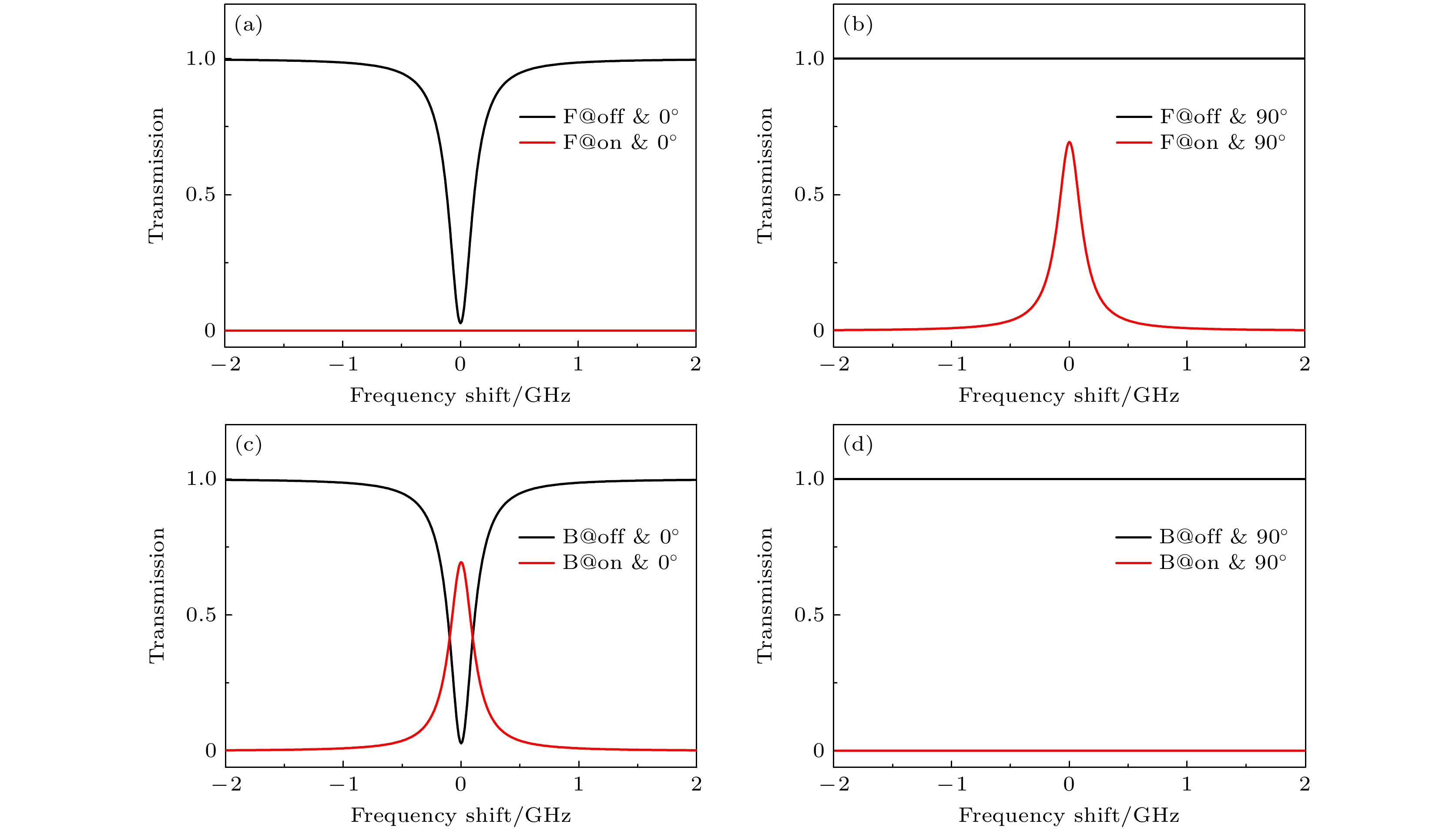
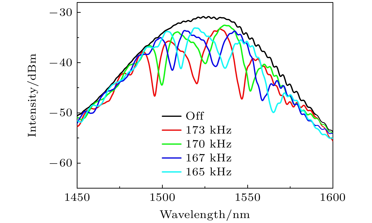
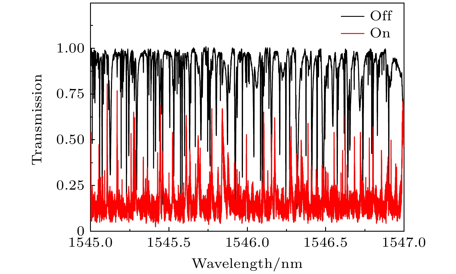
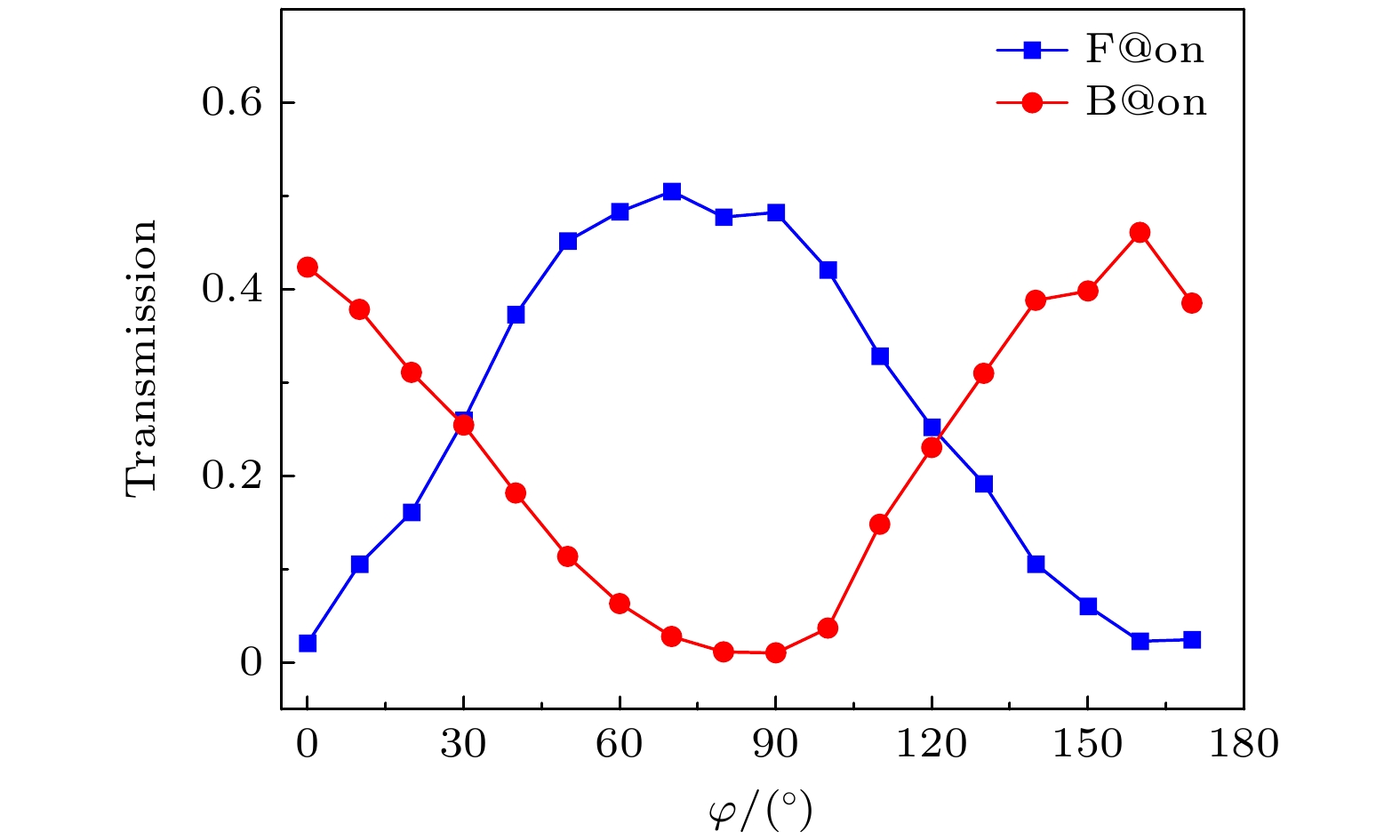
本文提出利用级联声光效应器和耦合回音壁模式微球腔的方案来实现非对称传输效果, 并进行理论和实验验证. 实验中利用加热拉锥的方式制备了两段式光纤, 可同时实现声光效应的激发和回音壁模式的耦合. 利用光纤中声光效应将纤芯基模中的矢量模式转换到包层高阶模式, 由于基模中不同矢量模式转换包层模式的矢量模式也不同, 从而产生类似双折射效果, 使输出的包层模式产生偏振变化. 而后通过耦合回音壁模式微腔将包层模式转换回纤芯基模. 由于回音壁模式的偏振选择效果, 使得相反方向入射光能量具有不同的透射特性, 其传输隔离度可达17 dB. 此外, 对两个方向传输的透射率随偏振角度变化进行测试, 测得声光效应带来的偏振变化约为80°. 本文的非对称传输方案继承了声光器件响应迅速、调谐性良好的优势, 同时具有全光纤结构和无工作阈值的特点, 在光开关、光隔离器等场景具有重要的应用潜力.In this paper, an asymmetric transmission scheme is proposed by cascading an acousto-optic device and a coupled whispering gallery mode (WGM) microsphere cavity, and it is demonstrated theoretically and experimentally. With the acousto-optic interaction in a fiber, the vector modes of the fundamental core mode can be converted into the different vector modes of a cladding (linear polarization, LP) mode, and because of the optical path difference between the cladding vector modes, the polarization of the cladding mode will be changed. The cladding mode can be converted back into the core fundamental mode by coupling a WGM microcavity. By calculating the overlapping of the mode fields in the tapered fiber and the microcavity at the resonance wavelength, the coupling coefficients between different LP modes and WGM will be solved. And, the transmitivities and conversion coefficients of the two fiber modes can be obtained on condition that the polarization of the incident light does not coincide with the polarization orientation of the WGM. The transmission spectra of the coupled WGM microcavity are calculated by using Matlab program for eight states, including the states at different incident directions, different incident polarizations of input, whether the acoustic wave is on or off. The results show that the conversion coefficient from the cladding mode to the core mode is completely different from that of the contrary process when the acoustic wave is working. And the forward incident light and backward incident light have completely different transmission characteristics, thus resulting in the asymmetric transmission. The transmittances of forward incidence and reverse incidence at different polarizations are also studied, both of them change periodically with the polarization angle, and their phase difference is equal to the polarization change caused by acousto-optic interaction in the fiber. In the experiment, a two-stage tapered fiber is used to realize the acousto-optic interaction and the coupling of whispering gallery mode at the same time. By controlling the working states of the system, the same 8 states as in the calculation are studied experimentally. The results show that due to the polarization-selection effect of the WGM, the light energy incident from the opposite directions will show different transmission characteristics. While the forward transmittance reaches a maximum value of about 0.505, the reverse transmittance reaches a minimum value of about 0.010, and the transmission isolation reaches about 17 dB. The transmittances in two directions are measured at different incident polarization angles, the transmission isolation is analyzed, and the polarization change of cladding mode in the fiber is verified to be about
${80^ \circ }$ . The measured results coincide with the calculations from the developed theory well. Finally, the shortcomings and optimization method of the scheme are discussed. The asymmetric transmission scheme in this paper inherits the advantages of rapid response and good tuning of acousto-optic device, and has an all-fiber structure, which has important application potential in optical switch and isolator.-
Keywords:
- asymmetric transmission /
- acousto-optic effect /
- whispering gallery mode microcavity /
- mode conversion
[1] Fujii Y, Member S 1991 J. Lightwave Technol. 9 1238
 Google Scholar
[2] Li Z, Zhang J J, Zhi Y Y, Li L Z, Liao B L, Yao J P 2022 Commun. Phys. 5 332
 Google Scholar
[3] Jalas D, Petrov A, Eich M, et al. 2013 Nat. Photon. 7 579
 Google Scholar
[4] Bi L, Hu J J, Jiang P, Kim D H, Dionne G F, Kimerling L C, Ross C A 2011 Nat. Photon. 5 758
 Google Scholar
[5] Cakmakyapan S, Serebryannikov A E, Caglayan H, Ozbay E 2010 Opt. Lett. 35 2597
 Google Scholar
[6] Cakmakyapan S, Serebryannikov A E, Caglayan H, Ozbay E 2012 Opt. Express 20 26636
 Google Scholar
[7] Cicek A, Yucel M B, Kaya O A, Ulug B 2012 Opt. Lett. 37 2937
 Google Scholar
[8] Xu T, Lezec H J 2014 Nat. Commun. 5 4141
 Google Scholar
[9] Zhu Z H, Liu K, Xu W, Luo Z, Guo C C, Yang B, Ma T, Yuan X D, Ye W M 2012 Opt. Lett. 37 4008
 Google Scholar
[10] Mutlu M, Akosman A E, Serebryannikov A E, Ozbay E 2012 Phys. Rev. Lett. 108 213905
 Google Scholar
[11] Chang L, Jiang X, Hua S, Yang C, Wen J, Jiang L, Li G, Wang G, Xiao M 2014 Nat. Photon. 8 524
 Google Scholar
[12] Dong C H, Shen Z, Zou C L, Zhang Y L, Fu W, Guo G C 2015 Nat. Commun. 6 6193
 Google Scholar
[13] Huang X Y, Liu Y C 2023 Phys. Rev. A 107 023703
 Google Scholar
[14] Zhang W, Huang L, Gao F, Bo F, Zhang G, Xu J 2013 Opt. Express 21 16621
 Google Scholar
[15] Lu J F, Meng L H, Shi F, et al. 2018 Opt. Lett. 43 5841
 Google Scholar
[16] Zhang W D, Huang L G, Gao F, Bo F, Xuan L, Zhang G Q, Xu J J 2012 Opt. Lett. 37 1241
 Google Scholar
[17] Kim B Y, Blake J N, Engan H E, Shaw H J 1986 Opt. Lett. 11 389
 Google Scholar
[18] Zhu Y, Guo A B, Xu J T, Zhang Z W, Pang F F, Zhang W J, Zeng X L, Sun J F 2023 Nanophotonics 12 3229
 Google Scholar
[19] Huang L G, Zhang W D, Li Y J, Han H N, Li X T, Chang P F, Gao F, Zhang G Q, Gao L, Zhu T 2018 Opt. Lett. 43 5431
 Google Scholar
[20] Huang L G, Zheng B W, Liu S L, et al. 2022 J. Lightwave Technol. 40 7396
 Google Scholar
[21] Zhang W D, Li X, Zhang L, Huang L G, Lu F F, Gao F 2020 IEEE J. Quantum Electron. 26 4
 Google Scholar
[22] Lu J F, Shi F, Xu J T, Meng L H, Zhang L K, Cheng P K, Zhou X, Pang F F, Zeng X L 2021 Nanophotonics 10 983
 Google Scholar
[23] Huang L G, Liu S L, Zhang C Z, Zhao Y X, Dang L Y, Gao L, Huang W, Yin G L, Zhu T 2023 Opt. Express 31 21253
 Google Scholar
[24] Bianucci P, Fietz C R, Robertson J W, Shvets G, Shih C K 2007 Opt. Lett. 32 2224
 Google Scholar
[25] Luo L W, Ophir N, Chen C P, Gabrielli L H, Poitras C B, Bergmen K, Lipson M 2014 Nat. Commun. 5 3069
 Google Scholar
[26] Monifi F, Friedlein J, Ozdemir S K, Yang L 2012 J. Lightwave Technol. 30 3306
 Google Scholar
[27] Huang L G, Wang J, Peng W H, et al. 2016 Opt. Lett. 41 638
 Google Scholar
[28] Li X T, Chang P F, Huang L G, Gao F, Zhang W D, Bo F, Zhang G Q, Xu J J 2018 Phys. Rev. A 98 053814
 Google Scholar
[29] Li B B, Xiao Y F, Zou C L, Liu Y C, Jiang X F, Chen Y L, Li Y, Gong Q H 2011 App. Phys. Lett. 98 021116
 Google Scholar
[30] Chang P F, Cao B T, Huang L G, et al. 2020 Sci. China Phys, Mech. 63 214211
 Google Scholar
[31] Chang P F, Cao B T, Gao F, et al. 2019 App. Phys. Lett. 115 211104
 Google Scholar
[32] Wang C, Zhang M, Stern B, Lipson M, Lončar M 2018 Opt. Express 26 1547
 Google Scholar
-
图 1 非对称传输原理示意图. Polarizer, 可调谐线性偏振滤波器; Horn, 声波耦合使用角锥; PZT, 压电陶瓷片; Input, 入射光; LP01, 线偏纤芯基模; LP11, 线偏包层模式; TE01, TM01为一阶横电、横磁模式; WGM, 回音壁模式; PD, 光探测器; AO effect area, 声光效应区; C-WGM area, 耦合回音壁微腔区; ${\kappa _0}$, 回音壁模式的本征损耗; ${\kappa _1}$, LP01与回音壁模式的耦合损耗; ${\kappa _2}$, LP11与回音壁模式的耦合损耗
Fig. 1. Schematic diagram of asymmetric transmission principle. Polarizer, tunable linear polarization filter; Horn, the corner cone for sonic coupling; PZT, piezoelectric ceramics; Input, input light; LP01, liner polarization mode in the fiber core; LP11, liner polarization mode in the fiber cladding; TE01 and TM01, first order transverse electric mode and transverse magnetic mode; WGM, whispering gallery mode cavity; PD, photodetector; AO effect area, the acousto-optic effect area; C-WGM area, coupling the WGM cavity area. ${\kappa _0}$, the intrinsic loss of WGM; $ {\kappa _1} $, the coupling loss between the LP01 and the WGM; ${\kappa _2}$, the coupling loss between the LP11 and the WGM.
图 2 两入射方向传输归一化透射率, “F”和“B”分别指代正向和反向传输的情况; “on”(红线)和“off”(黑线)分别指代有无光效应时的情况, 角度表示入射光偏振与回音壁模式偏振取向间的夹角$\varphi $
Fig. 2. Transmission of the two directions. “F” and “B” refer to the cases of forward and backward transmission respectively; “on” (red line) and “off” (black line) represent the situations of with and without the acousto-optic effect respectively; the angle ($\varphi $) is determined by the angle between the polarization directions of the input light and the WGM.
-
[1] Fujii Y, Member S 1991 J. Lightwave Technol. 9 1238
 Google Scholar
[2] Li Z, Zhang J J, Zhi Y Y, Li L Z, Liao B L, Yao J P 2022 Commun. Phys. 5 332
 Google Scholar
[3] Jalas D, Petrov A, Eich M, et al. 2013 Nat. Photon. 7 579
 Google Scholar
[4] Bi L, Hu J J, Jiang P, Kim D H, Dionne G F, Kimerling L C, Ross C A 2011 Nat. Photon. 5 758
 Google Scholar
[5] Cakmakyapan S, Serebryannikov A E, Caglayan H, Ozbay E 2010 Opt. Lett. 35 2597
 Google Scholar
[6] Cakmakyapan S, Serebryannikov A E, Caglayan H, Ozbay E 2012 Opt. Express 20 26636
 Google Scholar
[7] Cicek A, Yucel M B, Kaya O A, Ulug B 2012 Opt. Lett. 37 2937
 Google Scholar
[8] Xu T, Lezec H J 2014 Nat. Commun. 5 4141
 Google Scholar
[9] Zhu Z H, Liu K, Xu W, Luo Z, Guo C C, Yang B, Ma T, Yuan X D, Ye W M 2012 Opt. Lett. 37 4008
 Google Scholar
[10] Mutlu M, Akosman A E, Serebryannikov A E, Ozbay E 2012 Phys. Rev. Lett. 108 213905
 Google Scholar
[11] Chang L, Jiang X, Hua S, Yang C, Wen J, Jiang L, Li G, Wang G, Xiao M 2014 Nat. Photon. 8 524
 Google Scholar
[12] Dong C H, Shen Z, Zou C L, Zhang Y L, Fu W, Guo G C 2015 Nat. Commun. 6 6193
 Google Scholar
[13] Huang X Y, Liu Y C 2023 Phys. Rev. A 107 023703
 Google Scholar
[14] Zhang W, Huang L, Gao F, Bo F, Zhang G, Xu J 2013 Opt. Express 21 16621
 Google Scholar
[15] Lu J F, Meng L H, Shi F, et al. 2018 Opt. Lett. 43 5841
 Google Scholar
[16] Zhang W D, Huang L G, Gao F, Bo F, Xuan L, Zhang G Q, Xu J J 2012 Opt. Lett. 37 1241
 Google Scholar
[17] Kim B Y, Blake J N, Engan H E, Shaw H J 1986 Opt. Lett. 11 389
 Google Scholar
[18] Zhu Y, Guo A B, Xu J T, Zhang Z W, Pang F F, Zhang W J, Zeng X L, Sun J F 2023 Nanophotonics 12 3229
 Google Scholar
[19] Huang L G, Zhang W D, Li Y J, Han H N, Li X T, Chang P F, Gao F, Zhang G Q, Gao L, Zhu T 2018 Opt. Lett. 43 5431
 Google Scholar
[20] Huang L G, Zheng B W, Liu S L, et al. 2022 J. Lightwave Technol. 40 7396
 Google Scholar
[21] Zhang W D, Li X, Zhang L, Huang L G, Lu F F, Gao F 2020 IEEE J. Quantum Electron. 26 4
 Google Scholar
[22] Lu J F, Shi F, Xu J T, Meng L H, Zhang L K, Cheng P K, Zhou X, Pang F F, Zeng X L 2021 Nanophotonics 10 983
 Google Scholar
[23] Huang L G, Liu S L, Zhang C Z, Zhao Y X, Dang L Y, Gao L, Huang W, Yin G L, Zhu T 2023 Opt. Express 31 21253
 Google Scholar
[24] Bianucci P, Fietz C R, Robertson J W, Shvets G, Shih C K 2007 Opt. Lett. 32 2224
 Google Scholar
[25] Luo L W, Ophir N, Chen C P, Gabrielli L H, Poitras C B, Bergmen K, Lipson M 2014 Nat. Commun. 5 3069
 Google Scholar
[26] Monifi F, Friedlein J, Ozdemir S K, Yang L 2012 J. Lightwave Technol. 30 3306
 Google Scholar
[27] Huang L G, Wang J, Peng W H, et al. 2016 Opt. Lett. 41 638
 Google Scholar
[28] Li X T, Chang P F, Huang L G, Gao F, Zhang W D, Bo F, Zhang G Q, Xu J J 2018 Phys. Rev. A 98 053814
 Google Scholar
[29] Li B B, Xiao Y F, Zou C L, Liu Y C, Jiang X F, Chen Y L, Li Y, Gong Q H 2011 App. Phys. Lett. 98 021116
 Google Scholar
[30] Chang P F, Cao B T, Huang L G, et al. 2020 Sci. China Phys, Mech. 63 214211
 Google Scholar
[31] Chang P F, Cao B T, Gao F, et al. 2019 App. Phys. Lett. 115 211104
 Google Scholar
[32] Wang C, Zhang M, Stern B, Lipson M, Lončar M 2018 Opt. Express 26 1547
 Google Scholar
计量
- 文章访问数: 3402
- PDF下载量: 73
- 被引次数: 0


 下载:
下载:


