-
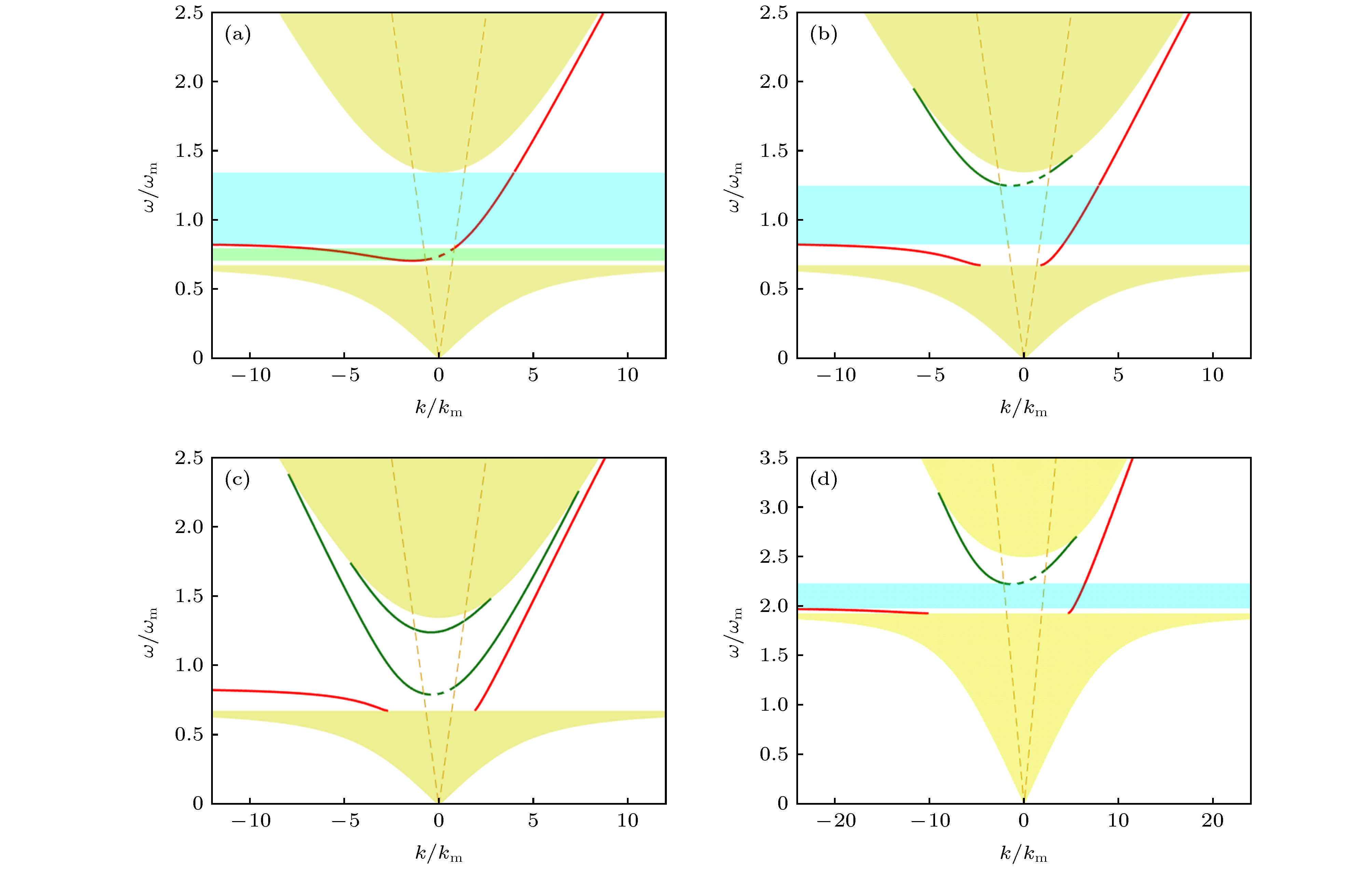
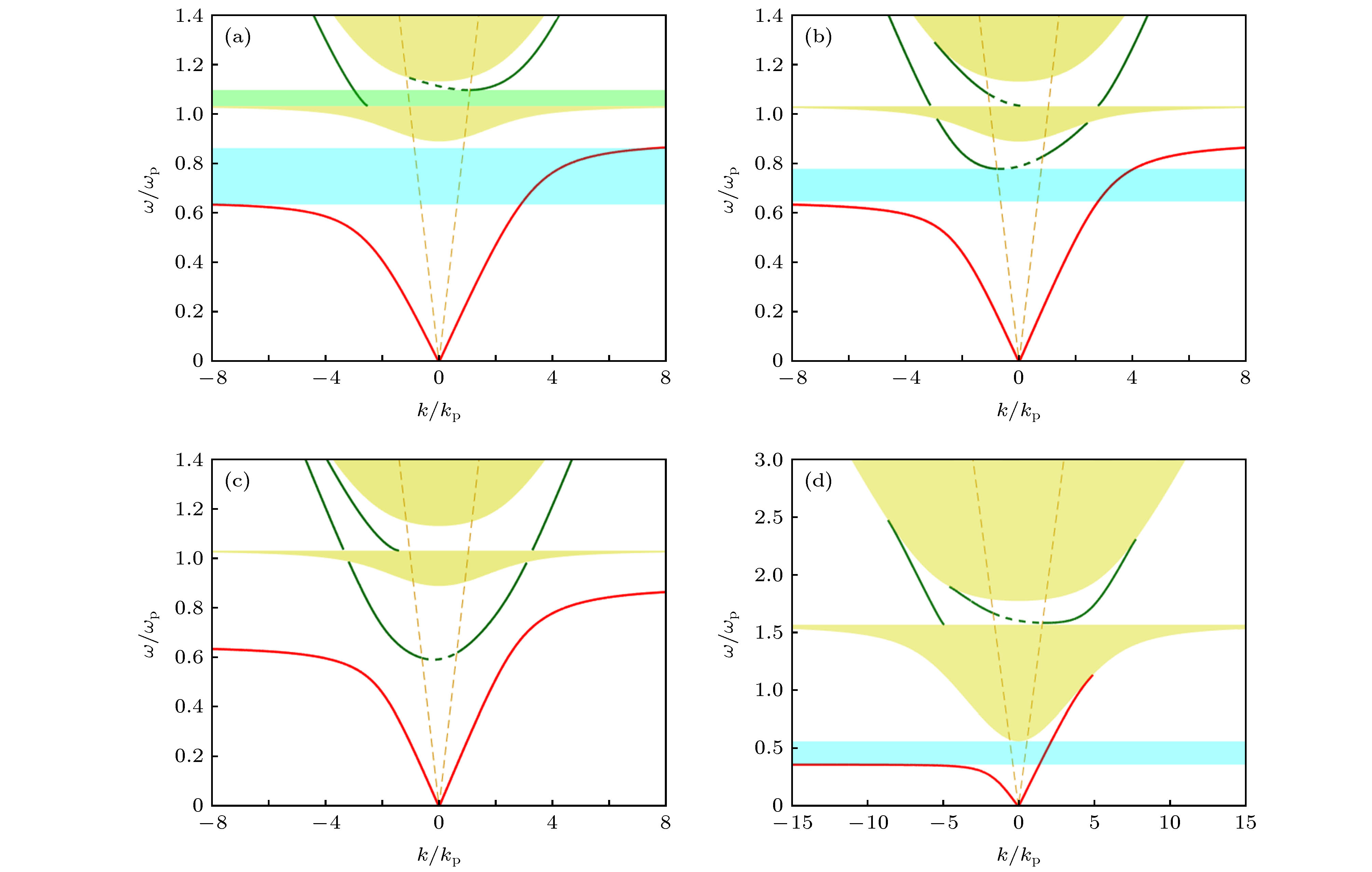
Surface magnetoplasmons (SMPs) is a kind of near-field electromagnetic wave, which propagates at the interface of dielectricand magneto-optical material under the action of biased magnetic field. Because SMPs have excellent anti-interference and backscattering-immune properties, it has attracted wide attention of researchers in recent years, but there are still many problems in the design of waveguide structures. When electromagnetic waves propagate in magneto-optical materials, the faraday rotation effect makes the bias magnetic field and the magnetic field vector (or electrical displacement vector) not in the same direction, so the anti-angle elements of the second-order matrix of magnetic permeability (or dielectric constant) are asymmetric. This asymmetrymakes electromagnetic waves non-reciprocal when propagating in specific directions in magneto-optical materials, and can even achieve one-way propagation in a certain frequency range. In this paper, a structure of three-layerplanar waveguide with silver, silicon, and magneto-optical material is studied. SMPs propagate at the interface between silicon and magneto-optical materials. This work numerically calculates the dispersion relation of the waveguide and the band gap of the magneto-optical material. It is found that both the fundamental mode and the higher-order mode of SMPs have one-way propagation characteristics in forward or backward directionwithin a specific frequency range. The dispersion relation of the planar waveguides with gyromagnetic material andgyroelectricmaterial are calculated respectively. As a result, the thickness of silicon layer and the external magnetic field have significant influence on bulk mode and the one-way propagation region of SMPs. By increasing the thickness of the silicon layer or increasing the intensity of the magnetic field, the higher-order mode can appear at the lower frequency region, thus compressing the one-way propagation region or even losing the one-way propagation mode. The one-way propagation bandwidth of planar waveguideswith gyromagnetic material YIG and gyroelectric material InSbare calculated. Bycalculating the dispersion relation of the waveguide SMPs and the band gap of the magneto-optical material for each group of magnetic field and the thickness of Si, the colormap of YIG waveguideand InSbwaveguide under 400–2000Oe magnetic field and 0.1–1 T magnetic field are obtained. As a result, the one-way mode of YIG waveguide appears in GHz band, and the maximum bandwidth for both forward and backward one-way propagation is 2.45 GHz. While, the one-way mode of InSbwaveguide appears in THz band, the maximum one-way propagation bandwidth in forward and backward directions are 3.9 THz and 3.12 THz. The research results in this paper are of great significance for the design and fabrication of non-reciprocal waveguides with one-waypropagation characteristics.
[1] Haldane F D M, Raghu S 2008 Phys. Rev. Lett. 100 013904
 Google Scholar
[2] Raghu S, Haldane F D M 2006 Phys. Rev. A 78 033834
[3] Hartstein A, Burstein E, Maradudin A A, Brewer R, Wallis R F 1973 J. Phys. C 6 1266
 Google Scholar
[4] Brion J J, Wallis R F, Hartstein A, Burstein E 1972 Phys. Rev. Lett. 28 1455
 Google Scholar
[5] Jiang C, Zhu H 2010 Opt. Express 18 006914
 Google Scholar
[6] 麦尔 著 (张彤 译) 2015 等离激元学—基础与应用 (南京: 东南大学出版社) 第14−23页
Maier S A (translated by Zhang T) 2015 Plasmonics: Fundamentas and Applications (Nanjing: Southeast University Press) pp14−23 (in Chinese)
[7] Khanikaev A B, Baryshev A V, Inoue M, Kivshar Y S 2009 Appl. Phys. Lett. 95 011101
 Google Scholar
[8] Kushwaha M S, Halevi P 1988 Phys. Rev. B 38 12428
 Google Scholar
[9] Shoji Y, Mizumoto T 2014 Sci. Technol. Adv. Mat. 15 014602
 Google Scholar
[10] ChenS, Fan F, Wang X, Wu P, Zhang H, Chang S 2015 Opt. Express 23 001015
 Google Scholar
[11] You Y, Deng X, Shen L, Wu J J, Yang T J 2016 Plasmonics 12 399
[12] Huang D, Pintus P, Zhang C, Paul M, Yuya S, Tetsuya M 2017 Optica 4 000023
 Google Scholar
[13] Fei F, ChuanZX, Jie R C, Jiang C S 2018 Opt. Lett. 43 000687
 Google Scholar
[14] Hu B, Wang Q J, Zhang Y 2012 Opt. Express 20 010071
 Google Scholar
[15] Shen L F, You Y, Wang Z Y, Deng X H 2015 Opt. Express 23 000950
 Google Scholar
[16] Kwiecien P, Richter I, Kuzmiak V, Ctyroky J 2017 J. Opt. Soc. Am. A 34 000892
 Google Scholar
[17] 王慧莹, 王智, 崔粲, 李航天, 李强, 詹翔空, 王健, 吴重庆 2019 68 154203
 Google Scholar
Wang H Y, Wang Z, Cui C, Li H T, Li Q, Zhan X K, Wang J, Wu C Q 2019 Acta Phys. Sin. 68 154203
 Google Scholar
[18] Tien M C, Mizumoto T, Pintus P, Kromer H, Bowers J E 2011 Opt. Express 19 011740
 Google Scholar
[19] Bi L, Hu J, Jiang P, Kim D H, Dionne G F, Kimerling L C, Ross C A 2011 Nat. Photonics 5 758
 Google Scholar
[20] Qianyi M U, Fan F, Chen S, Xu S T, Xiong C Z, Zhang X, Wang X H, Chang S J 2019 Photonics Res. 7 000325
 Google Scholar
[21] 波扎 著 (张肇仪 译) 2015 微波工程 (第3版) (北京: 电子工业出版社) 第380−386页
Pozar D M (translated by Zhang Z Y)2015 Microwave Engineering (3rd Ed.) (Beijing: Publishing House of Electronics Industry) pp380−386 (in Chinese)
-
图 2 磁流线源激励的单向传播模式, 图中显示电场振幅沿传播方向的演化. (Si厚度为9.6 μm, 磁光材料为8 μm厚的InSb, 外加磁场强度为0.3 T, 电磁波频率为1.56 THz)
Figure 2. The one-way propagation mode of the magnetic current source excitation, the figure shows the evolution of the electric field amplitude along the propagation direction. (The thickness of the Si and magneto-optical materials InSb are 0.6 μm and 8 μm, the applied magnetic field strength is 0.3 T, and the electromagnetic frequency is 1.56 THz.)
-
[1] Haldane F D M, Raghu S 2008 Phys. Rev. Lett. 100 013904
 Google Scholar
[2] Raghu S, Haldane F D M 2006 Phys. Rev. A 78 033834
[3] Hartstein A, Burstein E, Maradudin A A, Brewer R, Wallis R F 1973 J. Phys. C 6 1266
 Google Scholar
[4] Brion J J, Wallis R F, Hartstein A, Burstein E 1972 Phys. Rev. Lett. 28 1455
 Google Scholar
[5] Jiang C, Zhu H 2010 Opt. Express 18 006914
 Google Scholar
[6] 麦尔 著 (张彤 译) 2015 等离激元学—基础与应用 (南京: 东南大学出版社) 第14−23页
Maier S A (translated by Zhang T) 2015 Plasmonics: Fundamentas and Applications (Nanjing: Southeast University Press) pp14−23 (in Chinese)
[7] Khanikaev A B, Baryshev A V, Inoue M, Kivshar Y S 2009 Appl. Phys. Lett. 95 011101
 Google Scholar
[8] Kushwaha M S, Halevi P 1988 Phys. Rev. B 38 12428
 Google Scholar
[9] Shoji Y, Mizumoto T 2014 Sci. Technol. Adv. Mat. 15 014602
 Google Scholar
[10] ChenS, Fan F, Wang X, Wu P, Zhang H, Chang S 2015 Opt. Express 23 001015
 Google Scholar
[11] You Y, Deng X, Shen L, Wu J J, Yang T J 2016 Plasmonics 12 399
[12] Huang D, Pintus P, Zhang C, Paul M, Yuya S, Tetsuya M 2017 Optica 4 000023
 Google Scholar
[13] Fei F, ChuanZX, Jie R C, Jiang C S 2018 Opt. Lett. 43 000687
 Google Scholar
[14] Hu B, Wang Q J, Zhang Y 2012 Opt. Express 20 010071
 Google Scholar
[15] Shen L F, You Y, Wang Z Y, Deng X H 2015 Opt. Express 23 000950
 Google Scholar
[16] Kwiecien P, Richter I, Kuzmiak V, Ctyroky J 2017 J. Opt. Soc. Am. A 34 000892
 Google Scholar
[17] 王慧莹, 王智, 崔粲, 李航天, 李强, 詹翔空, 王健, 吴重庆 2019 68 154203
 Google Scholar
Wang H Y, Wang Z, Cui C, Li H T, Li Q, Zhan X K, Wang J, Wu C Q 2019 Acta Phys. Sin. 68 154203
 Google Scholar
[18] Tien M C, Mizumoto T, Pintus P, Kromer H, Bowers J E 2011 Opt. Express 19 011740
 Google Scholar
[19] Bi L, Hu J, Jiang P, Kim D H, Dionne G F, Kimerling L C, Ross C A 2011 Nat. Photonics 5 758
 Google Scholar
[20] Qianyi M U, Fan F, Chen S, Xu S T, Xiong C Z, Zhang X, Wang X H, Chang S J 2019 Photonics Res. 7 000325
 Google Scholar
[21] 波扎 著 (张肇仪 译) 2015 微波工程 (第3版) (北京: 电子工业出版社) 第380−386页
Pozar D M (translated by Zhang Z Y)2015 Microwave Engineering (3rd Ed.) (Beijing: Publishing House of Electronics Industry) pp380−386 (in Chinese)
Catalog
Metrics
- Abstract views: 9461
- PDF Downloads: 131
- Cited By: 0


 DownLoad:


