-
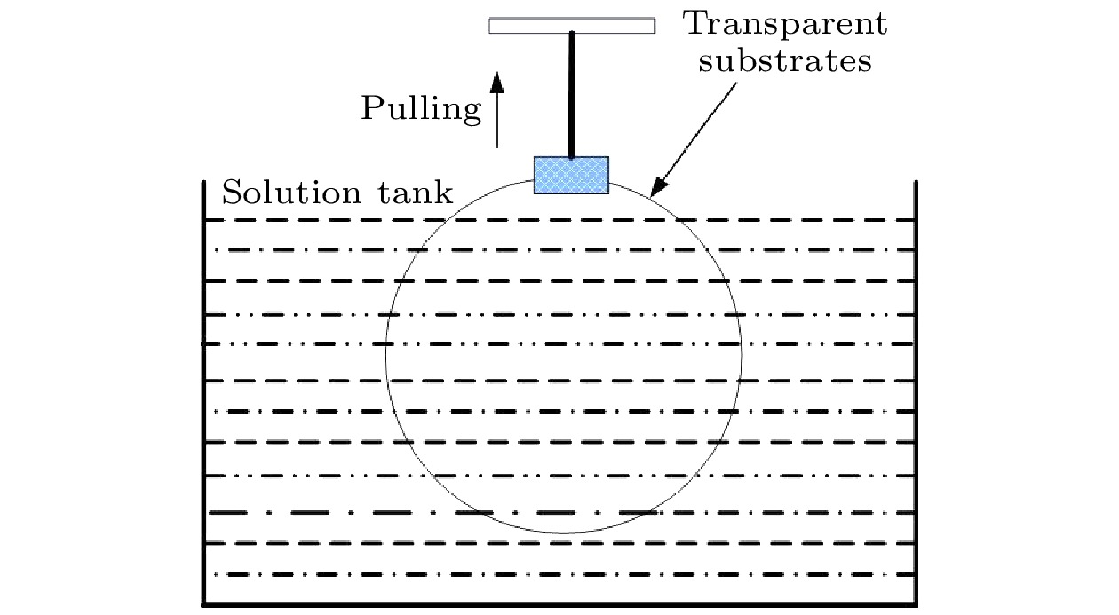
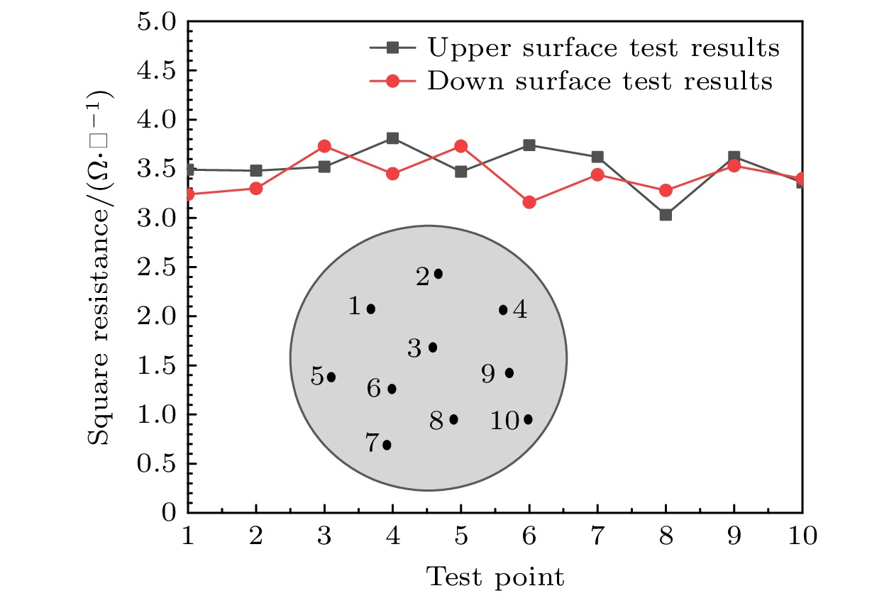
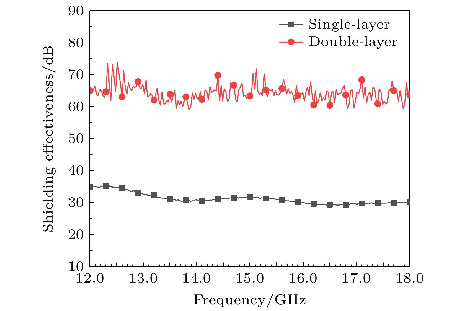
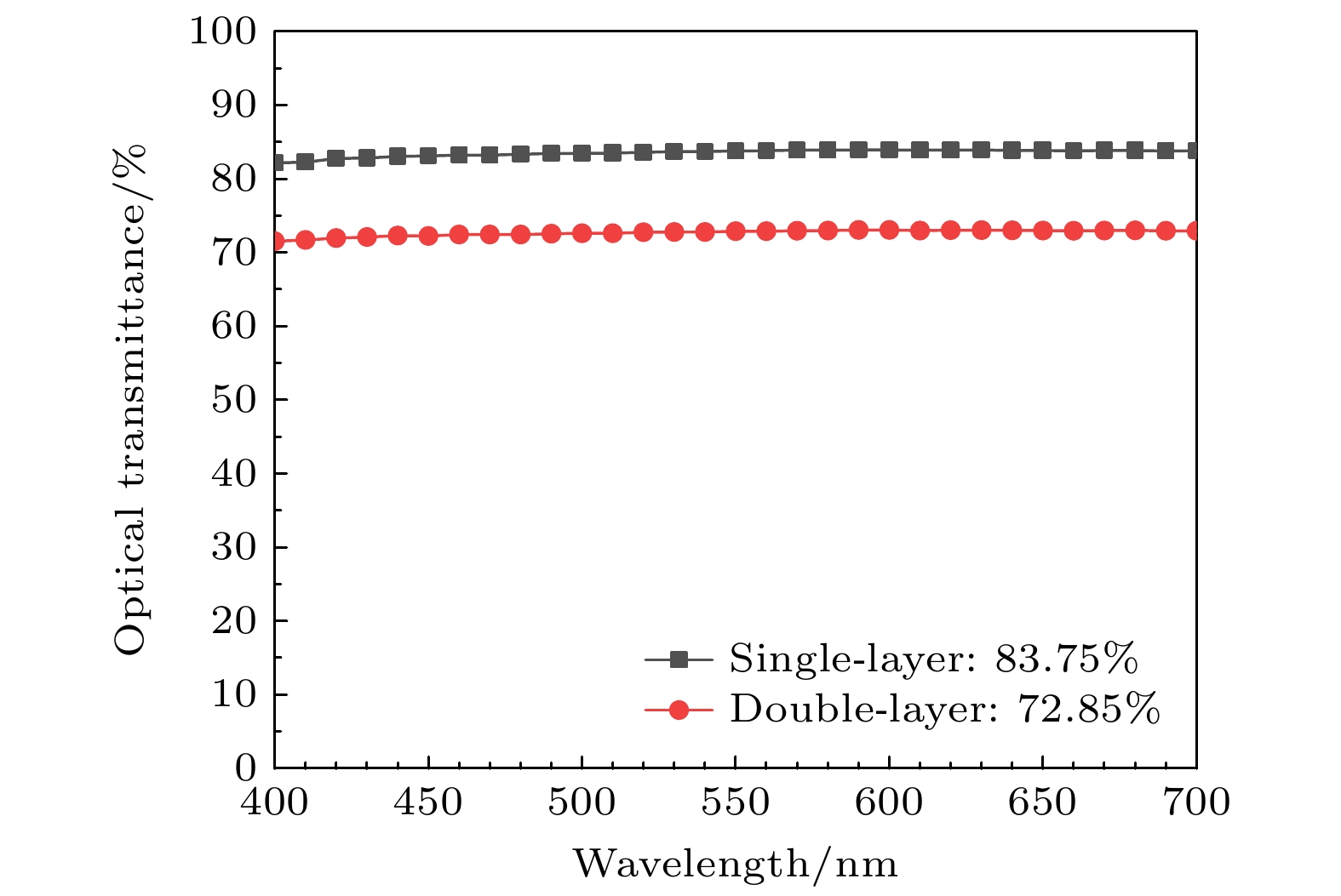
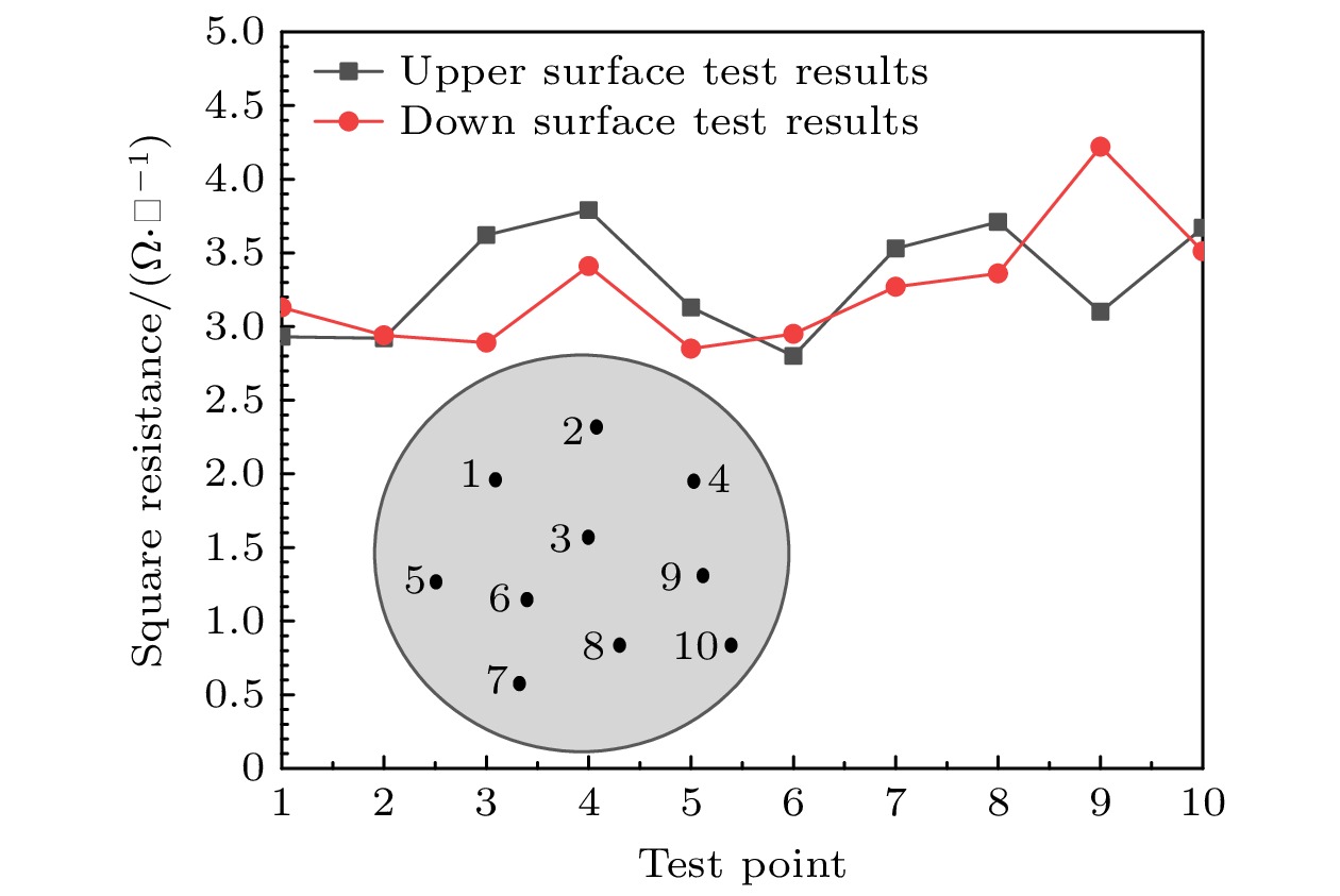
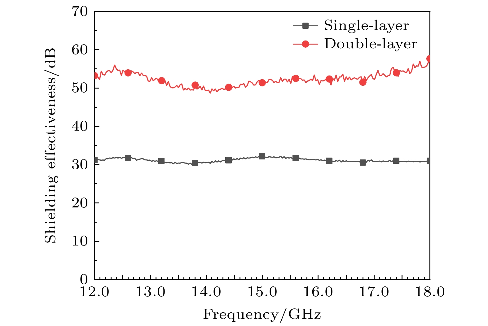
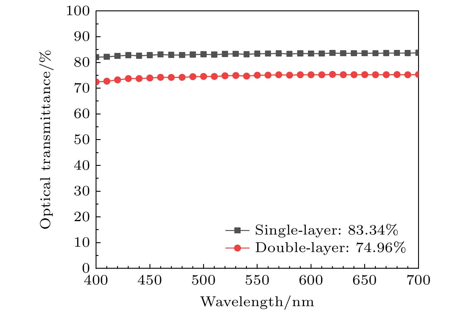
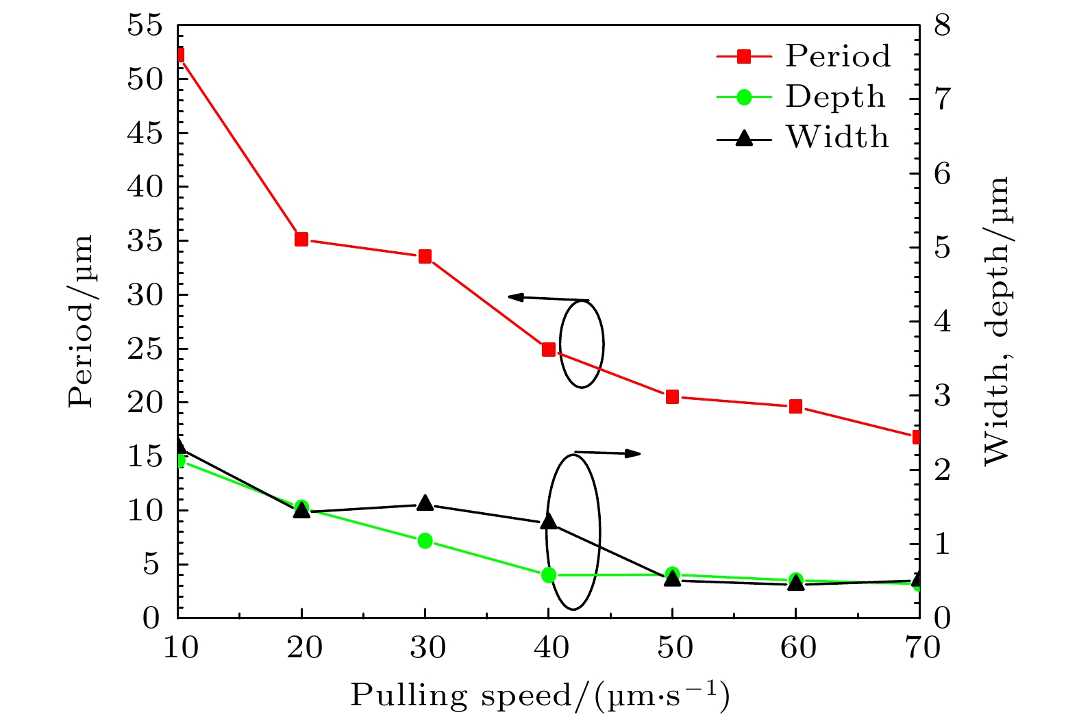
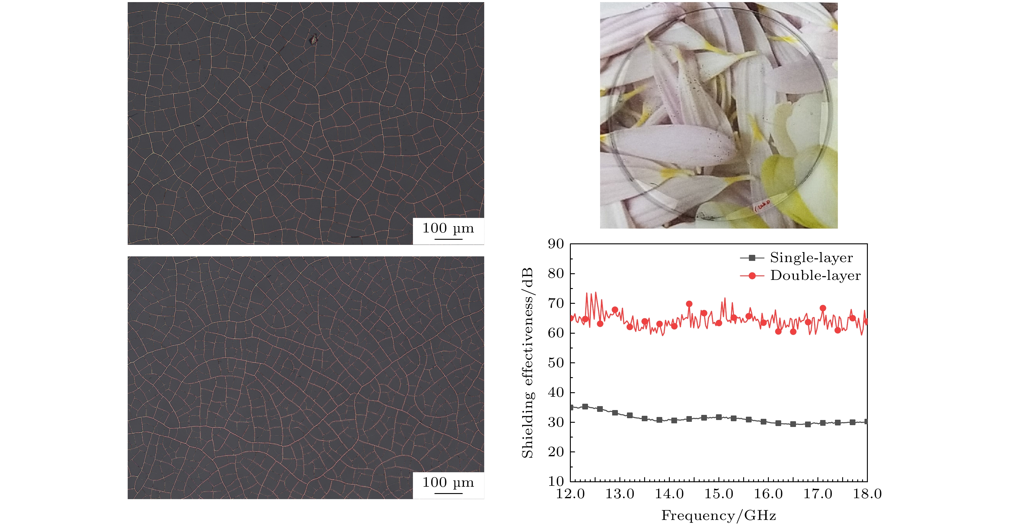
In order to improve the electromagnetic shielding performance of the single-layer metal mesh transparent conductive films (SMMTCFs) based on the crack template method, the preparation of double-layer metal mesh transparent conductive films (DMMTCFs) by using the crack template method is studied. The double-layer cracked templates are prepared by spin-coating crack glue on both sides of the transparent substrate and by pulling the transparent substrate from the cracked adhesive solution with a certain rate to obtain the corresponding double-layer cracked templates, respectively. After obtaining the double-layer crack templates by the spin-coating method and the pulling method, respectively, the corresponding DMMTCF samples are obtained by metal deposition and degumming process. First, the performances of single-layer and double-layer metal mesh samples prepared by the spin-coating method under the same conditions are measured and compared with each other, and the optical transmittance of the double-layer structure decreases by nearly 10.9% compared with that of the single-layer structure, while the electromagnetic shielding effectiveness in the Ku band (12–18 GHz) increases by 30 dB. In addition, the double-layer metal mesh sample prepared by the pulling method is also tested. Compared with the single-layer metal mesh sample prepared under the same conditions, the double-layer structure can improve electromagnetic shielding effectiveness in the Ku band by 20 dB under the premise of losing 8.38% optical transmittance. The measurement results show that the electromagnetic shielding performance of the double-layer metal mesh transparent conductive films can be significantly improved at the expense of some optical transmittance performances. Through the preparation and performance study of DMMTCFs based on the cracked template method, the low-cost advantage of the cracked template method can be fully utilized to prepare DMMTCFs with high electromagnetic shielding performance.
-
Keywords:
- crack template method /
- dual-layer metal mesh transparent conductive films /
- high electromagnetic shielding performance /
- magnetron sputtering
[1] Qiu L, Li L, Pan Z, Sun X, Yan W 2018 MATEC Web of Conferences 189 1003
 Google Scholar
[2] Wang W, Bai B, Zhou Q, Ni K, Lin H 2018 Opt. Mater. Express 8 3485
 Google Scholar
[3] Kai C, Wang K, Liu C 2019 10th EAI International Conference, WiSATS 2019, Part II Harbin, China, January 12–13, 2019 pp656–660
 Google Scholar
[4] Shi K, Su J, Hu K, Liang H 2020 J. Mater. Sci. Mater. Electron. 31 11646
 Google Scholar
[5] Corredores Y, Besnier P, Castel X, Sol J, Dupeyrat C, Foutrel P 2017 IEEE Trans. Electromagn. Compat. 59 1070
 Google Scholar
[6] Zhang Y, Dong H, Li Q, Mou N, Chen L, Zhang L 2019 RSC Adv. 9 22282
 Google Scholar
[7] Smith H A, Rebbert M, Sternberg O 2003 Appl. Phys. Lett. 82 3605
 Google Scholar
[8] Wang H, Lu Z, Liu Y, Tan J, Ma L, Lin S 2017 Opt. Lett. 42 1620
 Google Scholar
[9] Gu J, Hu S, Ji H, Feng H, Zhao W, Wei J, Li M 2020 Nanotechnology 31 185303
 Google Scholar
[10] Kaipa C S, Yakovlev A B, Medina F, Mesa F, Butler C A, Hibbins A P 2010 Opt. Express 18 13309
 Google Scholar
[11] Lu Z, Wang H, Tan J, Lin S 2014 Appl. Phys. Lett. 105 241904
 Google Scholar
[12] Lu Z, Liu Y, Wang H, Tan J 2016 Appl. Opt. 55 5372
 Google Scholar
[13] 廖敦微, 郑月军, 崔浩, 寸铁, 付云起 2022 光学精密工程 30 1310
 Google Scholar
Liao D W, Zheng Y J, Cui H, Cun T, Fu Y Q 2022 Opt. Precis. Eng. 30 1310
 Google Scholar
[14] Jiang Z, Zhao S, Huang W, Chen L, Liu Y H 2020 Opt. Express 28 26531
 Google Scholar
[15] Rao K D M, Hunger C, Gupta R, Kulkarni G U, Thelakkat M 2014 Phys. Chem. Chem. Phys. 16 15107
 Google Scholar
[16] Han B, Pei K, Huang Y, Zhang X, Rong Q, Lin Q, Guo Y, Sun T, Guo C, Carnahan D, Giersig M, Wang Y, Gao J, Ren Z, Kempa K 2014 Adv. Mater. 26 873
 Google Scholar
[17] Kiruthika S, Gupta R, Rao K D M, Chakraborty S, Padmavathy N, Kulkarni G U 2014 J. Mater. Chem. C 2 2089
 Google Scholar
[18] 肖宗湖, 王新莲, 韩春, 张帅旗, 付爽, 余玉玲 2018 新余学院学报 23 1
 Google Scholar
Xiao Z H, Wang X L, Han C, Zhang S Q, Fu S, Yu Y L 2018 J. Xinyu Univ. 23 1
 Google Scholar
[19] Han Y, Lin J, Liu Y, Fu H, Ma Y, Jin P, Tan J 2016 Sci. Rep. 6 25601
 Google Scholar
[20] Kim Y, Tak Y, Park S, Kim H 2017 Nanomaterials 7 214
 Google Scholar
[21] Muzzillo C P, Reese M O, Mansfield L M 2020 Langmuir 36 4630
 Google Scholar
[22] 廖敦微, 郑月军, 陈强, 丁亮, 高冕, 付云起 2022 71 154201
 Google Scholar
Liao D W, Zheng Y J, Chen Q, Ding L, Gao M, Fu Y Q 2022 Acta Phy. Sin. 71 154201
 Google Scholar
[23] Yang C, Merlo J M, Kong J, Xian Z, Han B, Zhou G, Gao J, Burns M J, Kempa K, Naughton M J 2018 Phys. Status Solidi A 215 1700504
 Google Scholar
[24] Voronin A S, Fadeev Y V, Govorun I V, Simunin M, Tambasov I A, Karpova D V, Smolyarova T E, Lukyanenko A V, Karacharov A, Nemtsev I V, Khartov S V 2021 J. Mater. Sci. 56 14741
 Google Scholar
[25] Voronin A S, Fadeev Y V, Makeev M O, Mikhalev P A, Osipkov A S, Provatorov A S, Ryzhenko D S, Yurkov G Y, Simunin Ml M, Karpova D V, Lukyanenko A V, Kokh D, Bainov D, Tambasov I A, Nedelin S V, Zolotovsky N A, Khartov S V 2022 Materials 15 1449
 Google Scholar
-
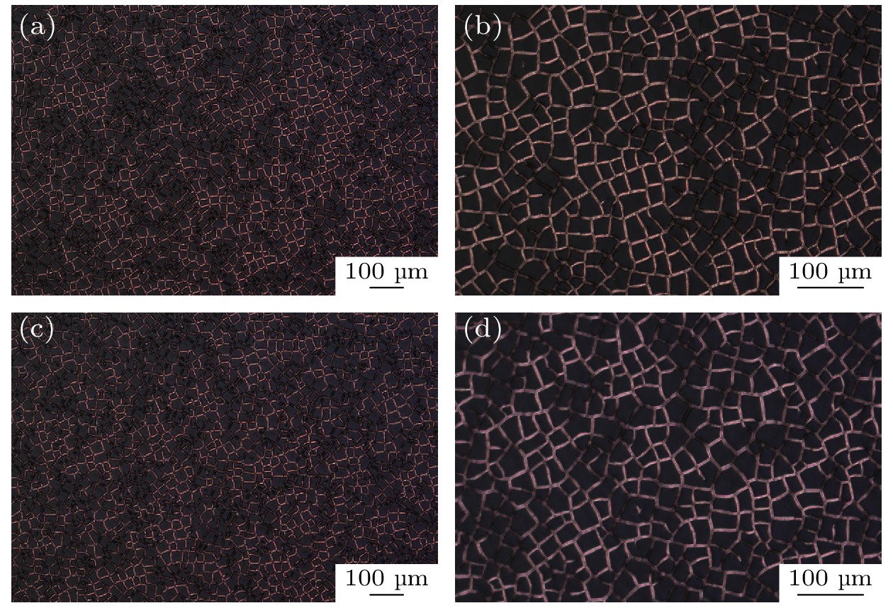
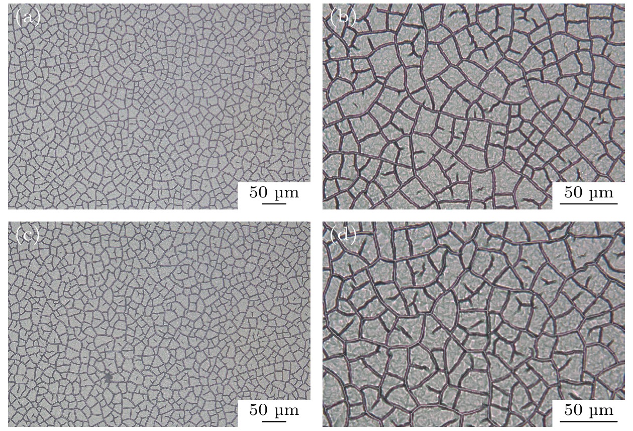
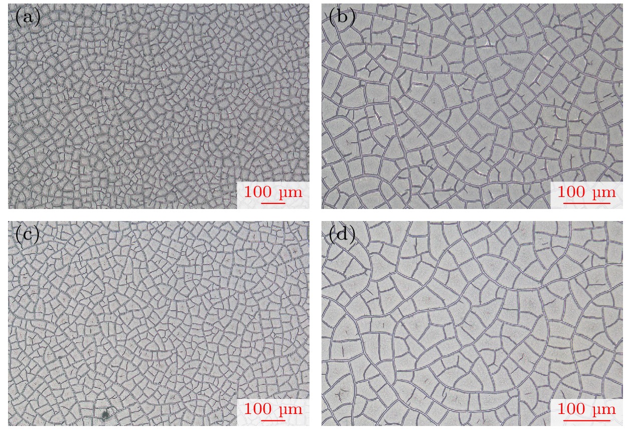
图 1 双层裂纹模板的金相显微镜观测结果图 (a) 10×镜头下的正面裂纹图案; (b) 20×镜头下的正面裂纹图案; (c) 10×镜头下的背面裂纹图案; (d) 20×镜头下的背面裂纹图案
Figure 1. Metallographic microscope observation pattern of the double-layer crack template: (a) Top crack pattern under 10× lens; (b) top crack pattern under 20× lens; (c) bottom crack pattern under 10× lens; (d) bottom crack pattern under 20× lens.
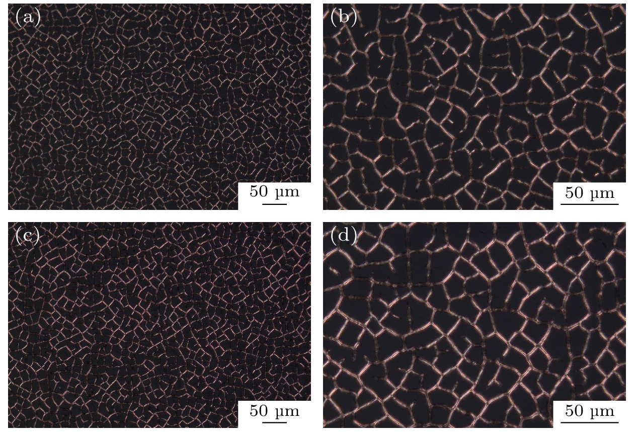
图 3 双层金属沉积样品的金相显微镜观测结果图 (a) 10×镜头下的正面金属沉积图案; (b) 20×镜头下的正面金属沉积图案; (c) 10×镜头下的背面金属沉积图案; (d) 20×镜头下的背面金属沉积图案
Figure 3. Metallographic microscope observation pattern of the double-layer metal deposition: (a) Top metal deposition pattern under 10× lens; (b) top metal deposition pattern under 20× lens; (c) bottom metal deposition pattern under 10× lens; (d) bottom metal deposition pattern under 20× lens.
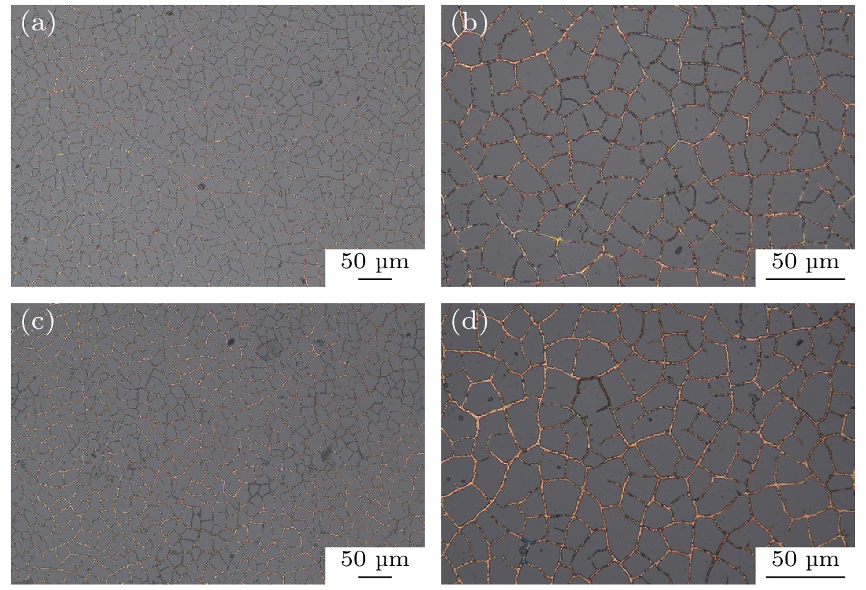
图 5 双层金属网格样品的金相显微镜观测结果图 (a) 10×镜头下的正面金属网格图案; (b) 20×镜头下的正面金属网格图案; (c) 10×镜头下的背面金属网格图案; (d) 20×镜头下的背面金属网格图案
Figure 5. Metallographic microscope observation pattern of the double-layer metal mesh: (a) Top metal mesh pattern under 10× lens; (b) top metal mesh pattern under 20× lens; (c) bottom metal mesh pattern under 10× lens; (d) bottom metal mesh pattern under 20× lens.
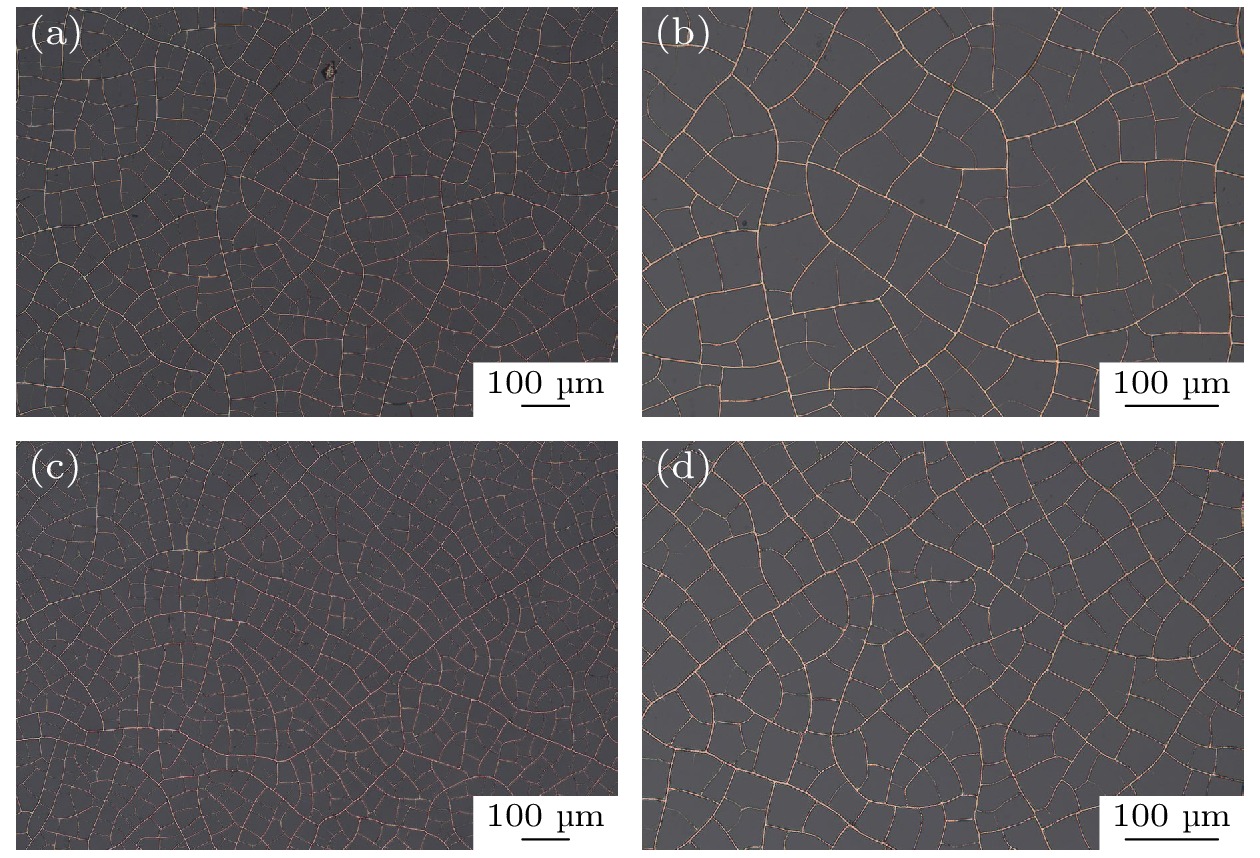
图 7 提拉法制备的双层裂纹模板的金相显微镜观测结果图 (a) 20×镜头下的正面裂纹图案; (b) 50×镜头下的正面裂纹图案; (c) 20×镜头下的背面裂纹图案; (d) 50×镜头下的背面裂纹图案
Figure 7. Metallographic microscope observation pattern of double-layer crack template by pulling method: (a) Top crack pattern under 20× lens; (b) top crack pattern under 50× lens; (c) bottom crack pattern under 20× lens; (d) bottom crack pattern under 50× lens.
图 9 提拉法制备双层金属沉积样品的金相显微镜观测结果图 (a) 20×镜头下的正面金属沉积图案; (b) 50×镜头下的正面金属沉积图案; (c) 20×镜头下的背面金属沉积图案; (d) 50×镜头下的背面金属沉积图案
Figure 9. Metallographic microscope observation pattern of the double-layer metal deposition by pulling method: (a) Top metal deposition pattern under 20× lens; (b) top metal deposition pattern under 50× lens; (c) bottom metal deposition pattern under 20× lens; (d) bottom metal deposition pattern under 50× lens.
图 11 提拉法制备的双层金属网格样品的金相显微镜观测结果图 (a) 20×镜头下的正面金属网格图案; (b) 50×镜头下的正面金属网格图案; (c) 20×镜头下的背面金属网格图案; (d) 50×镜头下的背面金属网格图案
Figure 11. Metallographic microscope observation pattern of the double-layer metal mesh by pulling method: (a) Top metal mesh pattern under 20× lens; (b) top metal mesh pattern under 50× lens; (c) bottom metal mesh pattern under 20× lens; (d) bottom metal mesh pattern under 50× lens
-
[1] Qiu L, Li L, Pan Z, Sun X, Yan W 2018 MATEC Web of Conferences 189 1003
 Google Scholar
[2] Wang W, Bai B, Zhou Q, Ni K, Lin H 2018 Opt. Mater. Express 8 3485
 Google Scholar
[3] Kai C, Wang K, Liu C 2019 10th EAI International Conference, WiSATS 2019, Part II Harbin, China, January 12–13, 2019 pp656–660
 Google Scholar
[4] Shi K, Su J, Hu K, Liang H 2020 J. Mater. Sci. Mater. Electron. 31 11646
 Google Scholar
[5] Corredores Y, Besnier P, Castel X, Sol J, Dupeyrat C, Foutrel P 2017 IEEE Trans. Electromagn. Compat. 59 1070
 Google Scholar
[6] Zhang Y, Dong H, Li Q, Mou N, Chen L, Zhang L 2019 RSC Adv. 9 22282
 Google Scholar
[7] Smith H A, Rebbert M, Sternberg O 2003 Appl. Phys. Lett. 82 3605
 Google Scholar
[8] Wang H, Lu Z, Liu Y, Tan J, Ma L, Lin S 2017 Opt. Lett. 42 1620
 Google Scholar
[9] Gu J, Hu S, Ji H, Feng H, Zhao W, Wei J, Li M 2020 Nanotechnology 31 185303
 Google Scholar
[10] Kaipa C S, Yakovlev A B, Medina F, Mesa F, Butler C A, Hibbins A P 2010 Opt. Express 18 13309
 Google Scholar
[11] Lu Z, Wang H, Tan J, Lin S 2014 Appl. Phys. Lett. 105 241904
 Google Scholar
[12] Lu Z, Liu Y, Wang H, Tan J 2016 Appl. Opt. 55 5372
 Google Scholar
[13] 廖敦微, 郑月军, 崔浩, 寸铁, 付云起 2022 光学精密工程 30 1310
 Google Scholar
Liao D W, Zheng Y J, Cui H, Cun T, Fu Y Q 2022 Opt. Precis. Eng. 30 1310
 Google Scholar
[14] Jiang Z, Zhao S, Huang W, Chen L, Liu Y H 2020 Opt. Express 28 26531
 Google Scholar
[15] Rao K D M, Hunger C, Gupta R, Kulkarni G U, Thelakkat M 2014 Phys. Chem. Chem. Phys. 16 15107
 Google Scholar
[16] Han B, Pei K, Huang Y, Zhang X, Rong Q, Lin Q, Guo Y, Sun T, Guo C, Carnahan D, Giersig M, Wang Y, Gao J, Ren Z, Kempa K 2014 Adv. Mater. 26 873
 Google Scholar
[17] Kiruthika S, Gupta R, Rao K D M, Chakraborty S, Padmavathy N, Kulkarni G U 2014 J. Mater. Chem. C 2 2089
 Google Scholar
[18] 肖宗湖, 王新莲, 韩春, 张帅旗, 付爽, 余玉玲 2018 新余学院学报 23 1
 Google Scholar
Xiao Z H, Wang X L, Han C, Zhang S Q, Fu S, Yu Y L 2018 J. Xinyu Univ. 23 1
 Google Scholar
[19] Han Y, Lin J, Liu Y, Fu H, Ma Y, Jin P, Tan J 2016 Sci. Rep. 6 25601
 Google Scholar
[20] Kim Y, Tak Y, Park S, Kim H 2017 Nanomaterials 7 214
 Google Scholar
[21] Muzzillo C P, Reese M O, Mansfield L M 2020 Langmuir 36 4630
 Google Scholar
[22] 廖敦微, 郑月军, 陈强, 丁亮, 高冕, 付云起 2022 71 154201
 Google Scholar
Liao D W, Zheng Y J, Chen Q, Ding L, Gao M, Fu Y Q 2022 Acta Phy. Sin. 71 154201
 Google Scholar
[23] Yang C, Merlo J M, Kong J, Xian Z, Han B, Zhou G, Gao J, Burns M J, Kempa K, Naughton M J 2018 Phys. Status Solidi A 215 1700504
 Google Scholar
[24] Voronin A S, Fadeev Y V, Govorun I V, Simunin M, Tambasov I A, Karpova D V, Smolyarova T E, Lukyanenko A V, Karacharov A, Nemtsev I V, Khartov S V 2021 J. Mater. Sci. 56 14741
 Google Scholar
[25] Voronin A S, Fadeev Y V, Makeev M O, Mikhalev P A, Osipkov A S, Provatorov A S, Ryzhenko D S, Yurkov G Y, Simunin Ml M, Karpova D V, Lukyanenko A V, Kokh D, Bainov D, Tambasov I A, Nedelin S V, Zolotovsky N A, Khartov S V 2022 Materials 15 1449
 Google Scholar
Catalog
Metrics
- Abstract views: 2410
- PDF Downloads: 120
- Cited By: 0


 DownLoad:

