-
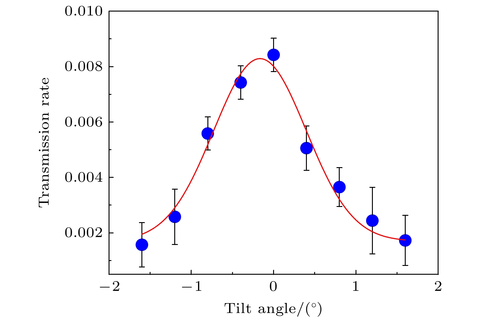
The study of low-energy, high-charge-state ions traversing insulating nanochannels has focused on the guiding effects due to the deposition of charge, while experimental and theoretical research on the influence of image charge forces caused by the polarization of the channel walls during ion transmission is relatively scarce. In this work, the experiments on 1-keV $ {\text{N}}_2^ + $ ion beams passing through muscovite microporous membranes are conducted by combining the theoretical method. Under the condition of complete discharge of the microporous membrane, the two-dimensional angular distribution of ejected ions at the initial stage of ion beam incidence at a zero-degree inclination is measured. In previous simulation calculations, first-order image force approximation and static approximation are used to calculate the image charge forces so as to simplify the calculation process. It is found that the results obtained from these calculations are still different from the experimental results. Therefore, we refine the calculation formula for image charge forces by taking into account the full effect of these forces. In previous studies of image charge forces, the influence of ion velocity on the polarization of the channel walls was neglected. The surface dielectric response theory of the image force experienced by ions within the micropores, which depends on ion velocity and the distance between the ion and the channel wall, is used to simulate and compare with the experimental results. The influence of image charge forces caused by surface dielectric response due to ion velocity on the angular distribution of ejected ions is studied. The discrepancies between the simulated and experimental two-dimensional angular distributions are found, showing that the experimental results have a wider half-height width than the simulated results. To explore the effects of beam divergence and the angle between the micropore axis and the beam on ion penetration and the two-dimensional angular distribution of ejected ions, simulation calculations for 1 keV $ {\text{N}}_2^ + $ under different beam conditions are conducted, with the third-order dynamic image charge forces considered. The several potential influences in the simulation calculations are analyzed, and the influences of the true state of the beam and the angle between the beam and the micropore on the difference between simulation and experiment are assessed. This work provides the possibility for studying the surface dielectric response of micropores by using ion beams as probes. -
Keywords:
- microporous membrane /
- image force /
- low charge state ion /
- dielectric response
[1] Spohr R, Bethge K 1990 Ion Tracks and Microtechnology (Wiesbaden: Vieweg Verlag) p1
[2] Martin C R 1994 Science 266 1961
 Google Scholar
[3] Stolterfoht N, Yamazaki Y 2016 Phys. Rep. 629 1
 Google Scholar
[4] Stolterfoht N, Bremer J H, Hoffmann V, Hellhammer R, Fink D, Petrov A, Sulik B 2002 Phys. Rev. Lett. 88 133201
 Google Scholar
[5] Zhang H Q, Akram N, Skog P, Soroka I L, Trautmann C, Schuch R 2012 Phys. Rev. Lett. 108 193202
 Google Scholar
[6] Iwai Y, Ikeda T, Kojima T M, Yamazaki Y, Maeshima K, Imamoto N, Kobayashi T, Nebiki T, Narusawa T, Pokhil G P 2008 Appl Phys. Lett. 92 023509
 Google Scholar
[7] Lemell C, Burgdörfer J, Aumayr F P 2013 Surf. Sci. 88 237
 Google Scholar
[8] Kanai Y, Hoshino M, Kambara T, Ikeda T, Hellhammer R, Stolterfoht N, Yamazaki Y 2009 Phys. Rev. A 79 012711
 Google Scholar
[9] Stolterfoht N 2013 Phys. Rev. A 87 012902
 Google Scholar
[10] Stolterfoht N 2013 Phys. Rev. A 87 032901
 Google Scholar
[11] Stolterfoht N, Hellhammer R, Juhász Z, et al. 2009 Phys. Rev. A 79 042902
 Google Scholar
[12] Rajendra-Kumar R T, Badel X, Vikor G, Linnros J, Schuch R 2005 Nanotechnology 16 1697
 Google Scholar
[13] Sahana M B, Skog P, Vikor G, Rajendra-Kumar R T, Schuch R 2006 Phys. Rev. A 73 040901
 Google Scholar
[14] Skog P, Zhang H Q, Schuch R 2008 Phys. Rev. Lett. 101 223202
 Google Scholar
[15] Zhang H Q, Skog P, Schuch R 2010 Phys. Rev. A 82 052901
 Google Scholar
[16] Mátéfi-Tempfli S, Mátéfi-Tempfli M, Piraux L, et al. 2006 Nanotechnology 17 3915
 Google Scholar
[17] Krause H F, Vane C R, Meyer F W 2007 Phys. Rev. A 75 042901
 Google Scholar
[18] Skog P, Soroka I L, Johansson A, Schuch R 2007 Nucl. Instrum. Methods Phys. Res., Sect. B 258 145
 Google Scholar
[19] Juhász Z, Sulik B, Biri S, et al. 2009 Nucl. Instrum. Methods Phys. Res., Sect. B 267 321
 Google Scholar
[20] Li D, Wang Y, Zhao Y, Xiao G, Zhao D, Xu Z, Li F 2009 Nucl. Instrum. Methods Phys. Res., Sect. B 267 469
 Google Scholar
[21] Stolterfoht N, Hellhammer R, Sulik B, et al. 2011 Phys. Rev. A 83 062901
 Google Scholar
[22] Schiessl K, Palfinger W, Tökési K, Nowotny H, Lemell C, Burgdörfer J 2005 Phys. Rev. A 72 062902
 Google Scholar
[23] Schiessl K, Palfinger W, Tökési K, Nowotny H, Lemell C, Burgdörfer J 2007 Nucl. Instrum. Methods Phys. Res. , Sect. B 258 150
 Google Scholar
[24] 李鹏飞, 袁华, 程紫东, 钱立冰, 刘中林, 靳博, 哈帅, 张浩文, 万城亮, 崔莹, 马越, 杨治虎, 路迪, Reinhold Schuch, 黎明, 张红强, 陈熙萌 2022 71 084104
 Google Scholar
Li P F, Yuan H, Cheng Z D, Qian L B, Liu Z L, Jin B, Ha S, Zhang H W, Wan C L, Cui Y, Ma Y, Yang Z H, Lu D, Schuch R, Li M, Zhang H Q, Chen X M 2022 Acta Phys. Sin. 71 084104
 Google Scholar
[25] 李鹏飞, 袁华, 程紫东, 钱立冰, 刘中林, 靳博, 哈帅, 万城亮, 崔莹, 马越, 杨治虎, 路迪, Reinhold Schuch, 黎明, 张红强, 陈熙萌 2022 71 074101
 Google Scholar
Li P F, Yuan H, Cheng Z D, Qian L B, Liu Z L, Jin B, Ha S, Wan C L, Cui Y, Ma Y, Yang Z H, Lu D, Schuch R, Li M, Zhang H Q, Chen X M 2022 Acta Phys. Sin. 71 074101
 Google Scholar
[26] 万城亮, 潘俞舟, 朱丽萍, 李鹏飞, 张浩文, 赵卓彦, 袁华, 樊栩宏, 孙文胜, 杜战辉, 陈乾, 崔莹, 廖天发, 魏晓慧, 王天琦, 陈熙萌, 李公平, Reinhold Schuch, 张红强 2024 73 104101
 Google Scholar
Wan C L, Pan Y Z, ZHU L P, Zhang H W, Zhao Z Y, Yuan H, Liu P F, Fan X H, Sun W S, DU Z H, Chen Q, Cui Y, Liao T F, Wei X H, Wang T Q, Chen X M, Li G P, Schuch R, Zhang H Q 2024 Acta Phys. Sin. 73 104101
 Google Scholar
[27] Pokhil G P, Vokhmyanina K A 2008 J. Surf. Invest. 2 p237
 Google Scholar
[28] Zhang H Q, Akram N, Soroka I L, Trautmann C, Schuch R 2012 Phys. Rev. A 86 022901
 Google Scholar
[29] Zhang H Q, Akram N, Schuch R 2016 Phys. Rev. A 94 032704
 Google Scholar
[30] Harris J, Jones R O 1974 J. Phys. C: Solid State Phys. 7 3751
 Google Scholar
[31] Wiza J L 1979 Nucl. Instrum. Methods. 162 587
 Google Scholar
[32] Lampton M, Carlson C W 1979 Rev. Sci. Instrum. 50 1093
 Google Scholar
[33] FASTER http://faster.in2p3.fr/
[34] Ackermann J, Angert N, Neumann R, Trautmann C, Dischner M, Hagen T, Sedlacek M 1996 Nucl. Instrum. Methods Phys. Res. , Sect. B 107 181
 Google Scholar
[35] Ward A A 2016 ResearchGate 2 10
 Google Scholar
[36] Giglio E 2023 Phys. Rev. A. 107 012816
 Google Scholar
[37] Petzelt J, Rychetský I 2005 Dielectric function, Encyclopedia of Condensed Matter Physics (Amsterdam: Elsevier) p426
[38] Beran A 2002 Rev. Mineral. Geochem. 46 351
 Google Scholar
[39] Fali A, Gamage S, Howard M, et al. 2021 ACS Photonics 8 175
 Google Scholar
[40] Agostinelli S, Allison J R, Amako K, et al. 2003 Nucl. Instrum. Methods Phys. Res., Sect. A 506 250
 Google Scholar
[41] Zhang Q, Liu Z L, Li P F, et al. 2018 Phys. Rev. A 97 042704
 Google Scholar
-
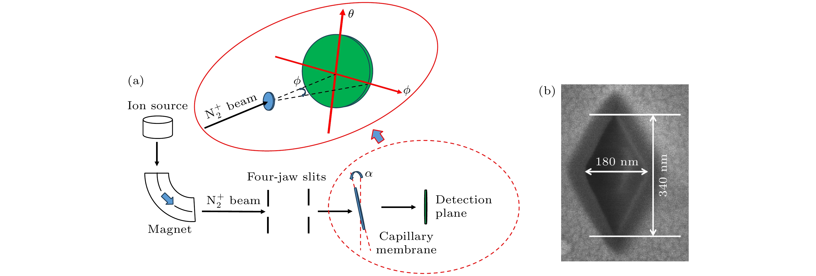
图 1 (a)实验装置的示意图. 倾角α代表毛细管轴线与入射束方向之间的夹角. 观察角ϕ是相对于入射束流方向和透射离子的方向的夹角来定义的. (b)通过化学蚀刻得到的云母膜微孔膜中单个微孔的SEM顶视图, 以及微孔的尺寸
Figure 1. (a) Schematic diagram of the experimental setup. The tilt angle α represents the angle between the axis of the capillaries and the direction of the incident beam. The observation angle ϕ is defined with respect to the direction of the incident beam and the transmitted ions as illustrated. (b) SEM top view of an individual pore in a muscovite mica membrane with rhombic capillaries obtained by chemical track etching, along with the dimensions of the capillaries.
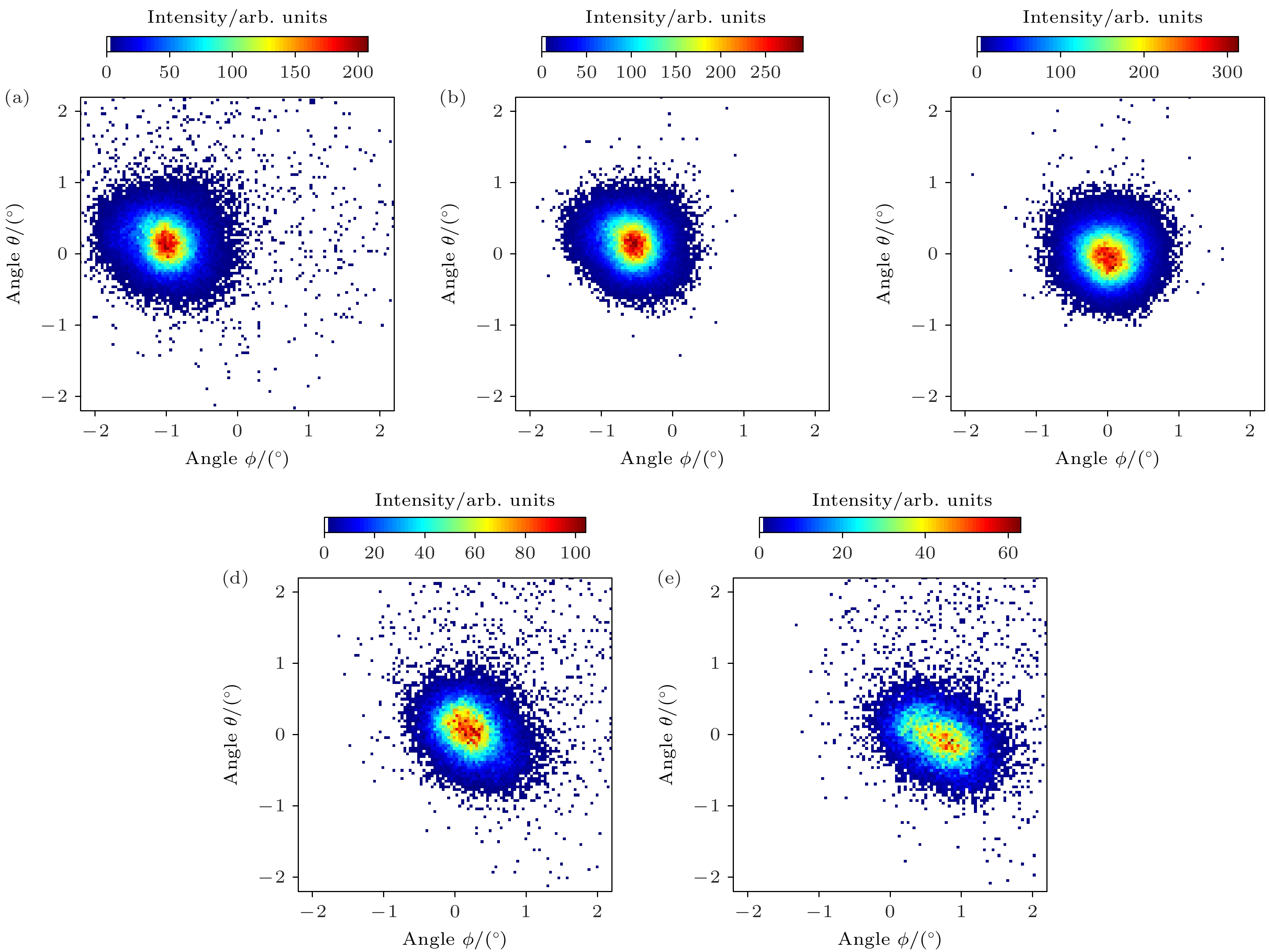
图 2 不同倾角下, 1 keV $ {\text{N}}_2^ + $ 离子穿越白云母微孔膜达到稳态时的实验透射离子二维角分布 (a) α = –0.8°; (b) α = –0.4°; (c) α = 0°; (d) α = 0.4°; (e) α = 0.8°
Figure 2. Exprimental two-dimensional angular distributions for 1 keV $ {\text{N}}_2^ + $ ions transmitted through phlogopite mica capillaries of rhombic cross-section during the steady state of transmission at various tilt angles: (a) α = –0.8°; (b) α = –0.4°; (c) α = 0°; (d) α = 0.4°; (e) α = 0.8°.
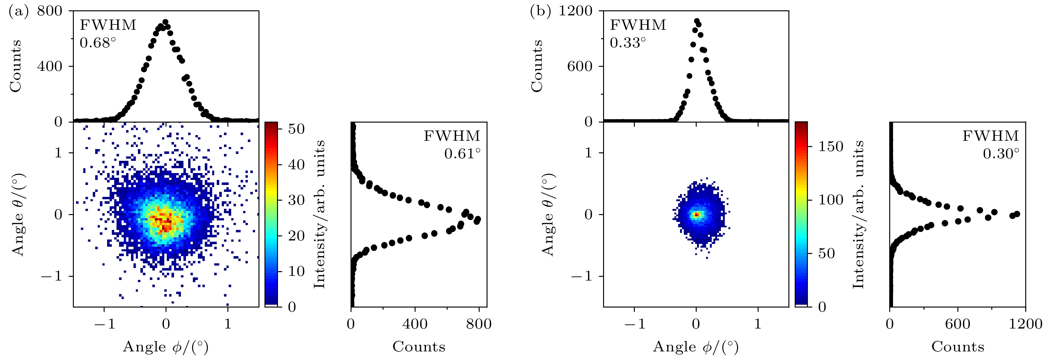
图 4 (a)束流发散度为1.3°, 靶倾角α = 0.1°, 1 keV $ {\text{N}}_2^ + $ 离子束刚开始入射时的透射离子角分布实验结果, 角分布上方为其在ϕ方向的投影, 投影半高宽为0.68°; 右边为角分布在θ方向的投影, 投影半高宽为0.61°. (b) 3阶动态镜像电荷力作用下对实验结果模拟计算的透射离子二维角分布, 角分布上方为其在ϕ方向的投影, 投影半高宽为0.33°; 右边为角分布在θ方向的投影, 投影半高宽为0.3°
Figure 4. (a) The title angle α = 0.1°, the transmission ion with a beam divergence of 1.3° experimental angular distribution of 1 keV $ {\text{N}}_2^ + $ ion beam just starting to strike, with the projection on the ϕ direction above the angular distribution, and the full width at half maximum of the projection is 0.68°; on the right is the projection of the angular distribution in the θ direction, with the full width at half maximum of the projection being 0.61°. (b) Simulated two-dimensional angular distribution of transmitted ions under the influence of third-order dynamic image charge force. The projection above the angular distribution is in the ϕ direction, with a full width at half maximum of 0.33°; the projection on the right is in the θ direction, with a full width at half maximum of 0.3°.
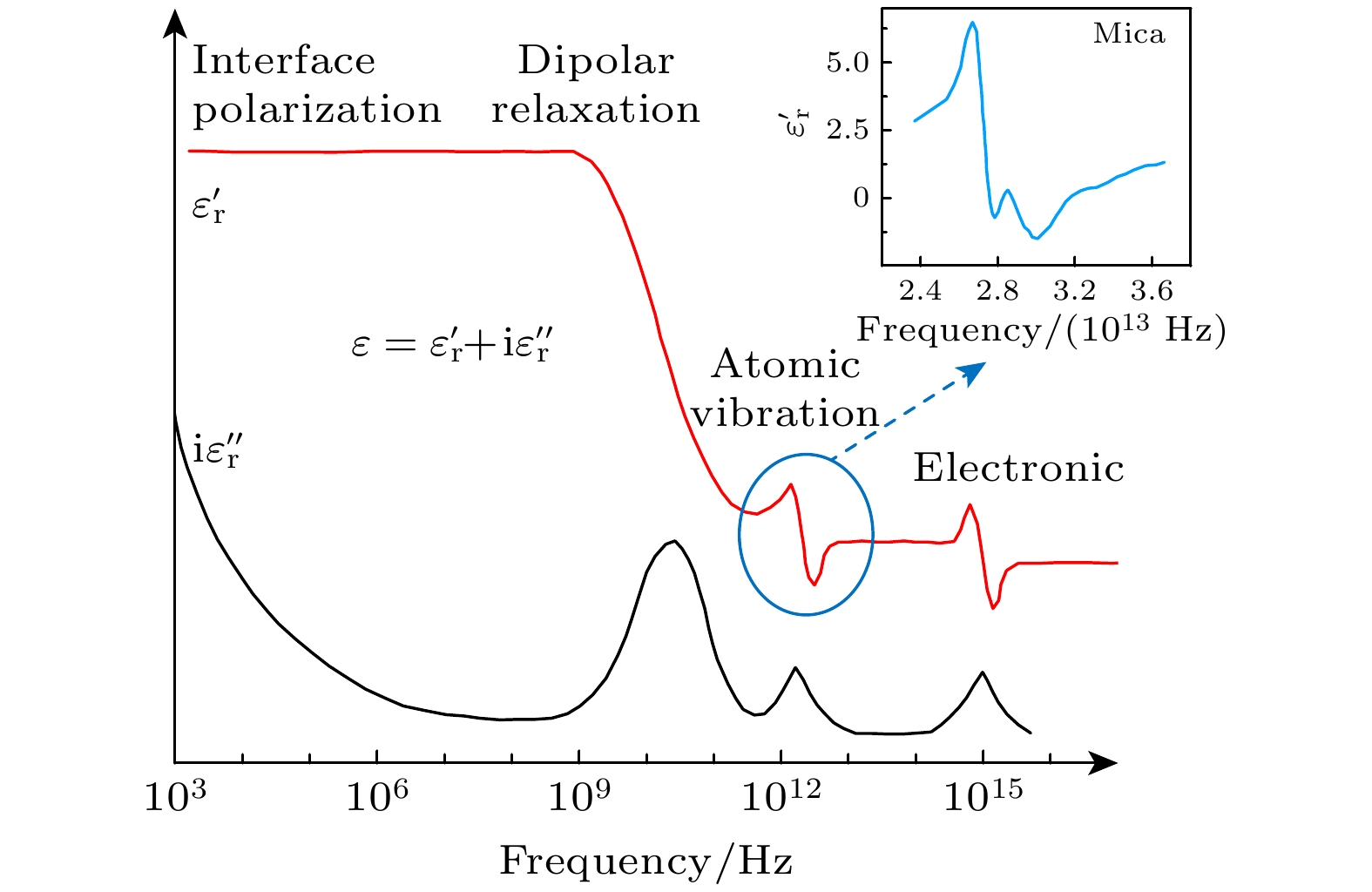
图 5 在很大频率范围内的任意介质介电谱[35]. 介电函数的实部$\varepsilon _{\text{r}}'$(红线)和虚部${\mathrm{i}}\varepsilon _{\text{r}}''$(黑线), 界面极化、偶极松弛、原子和电子在更高频率下的共振过程在图中标记; 右上角为24—36 THz下云母介电函数实部随电场角频率变化的曲线[38]
Figure 5. Arbitrary dielectric permittivity spectrum over a wide range of frequencies[35]. The real $\varepsilon _{\text{r}}'$ (red line) and imaginary ${\mathrm{i}}\varepsilon _{\text{r}}''$ part (black line) of permittivity are shown. Various processes are labeled: Interface polarization, dipolar relaxation, atomic, and electronic resonances at higher frequencies. The upper right corner shows the curve of the real part of the dielectric function of mica as a function of the electric field angular frequency in the 24–36 THz range[38].
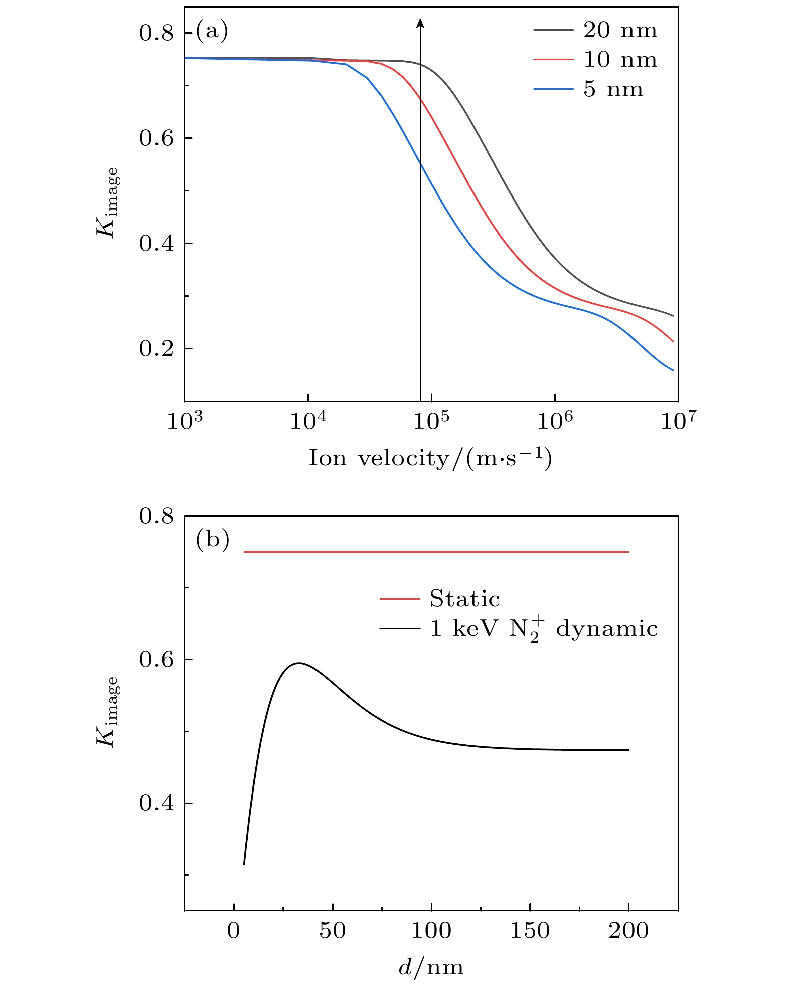
图 6 (a)离子距离通道壁20, 10, 5 nm, 极化因子随离子速度v的变化曲线. 图中箭头处为1 keV $ {\text{N}}_2^ + $对应的速度; (b) 1 keV $ {\text{N}}_2^ + $离子极化因子Kimage随离子与通道壁的距离d变化曲线, 速度趋向于零时的极化因子
Figure 6. (a) Polarization coefficient (Kimage) is presented as a function of ion velocity v for three different distances from the channel walls: 20, 10, and 5 nm; (b) the polarization coefficient (Kimage) of 1 keV $ {\text{N}}_2^ + $ ions in mica as a function of the distance d between the ions and the channel walls, with red line representing the static limit.
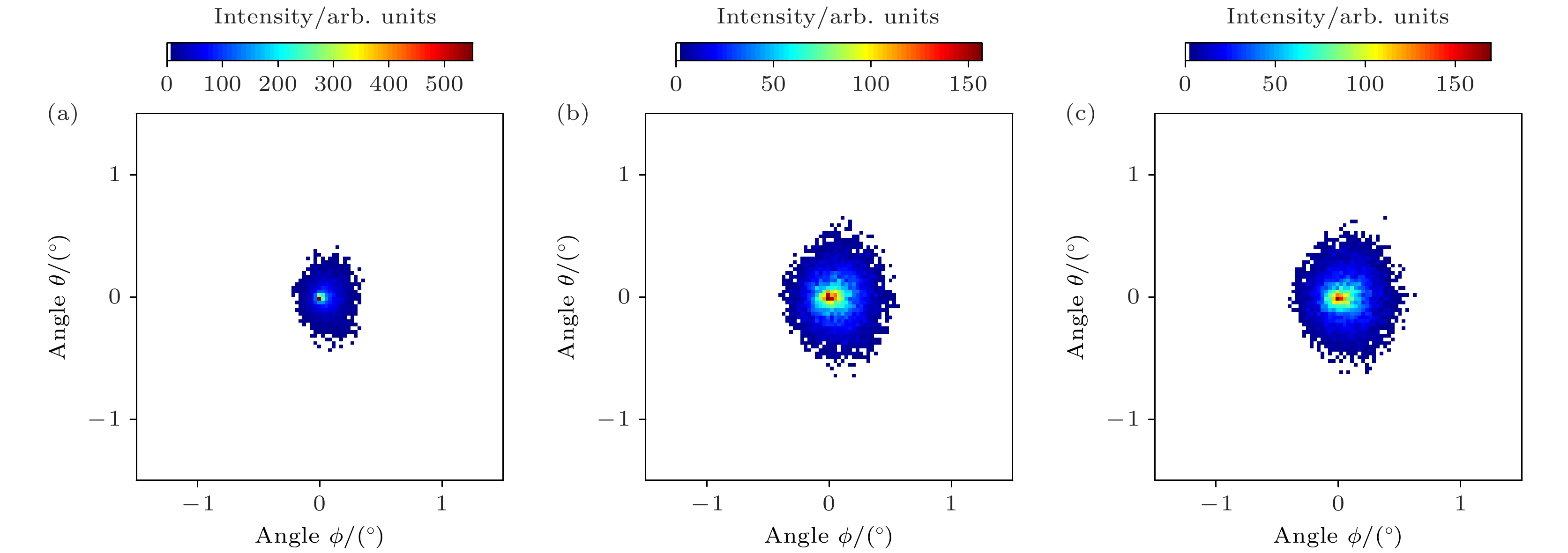
图 8 束流发散度为1.3°, 1 keV $ {\text{N}}_2^ + $离子穿越白云母微孔膜时在不同镜像电荷力作用下的模拟二维角分布 (a)不考虑镜像电荷力; (b)一阶静态镜像电荷力; (c)三阶静态镜像电荷力
Figure 8. Simulated two-dimensional angular distributions of 1 keV $ {\text{N}}_2^ + $ beam divergence at 1.3° under various image charge force conditions: (a) Without image charge force; (b) with first-order static image charge force; (c) with third-order static image charge force.
图 9 (a)倾角α = 0.1°, 束流发散度为1.3°的1 keV $ {\text{N}}_2^ + $离子穿越白云母微孔膜的实验穿透率以及不同镜像电荷力下模拟计算穿透率: 不考虑镜像电荷力、一阶静态镜像电荷力、三阶静态镜像电荷力、三阶动态镜像电荷力. (b)实验二维角分布半高宽以及模拟计算不同情况下的二维角分布半高宽: 不考虑镜像电荷力、一阶静态镜像电荷力、三阶静态镜像电荷力、三阶动态镜像电荷力
Figure 9. (a) The experimental transmission rate of 1 keV $ {\text{N}}_2^ + $ beam divergence at 1.3° and the simulated calculations for different scenarios, including no image charge force, first-order static image charge force, third-order static image charge force, and third-order dynamic image charge force. (b) Experimental two-dimensional angular distribution full width at half maximum (FWHM), as well as the simulated calculations for different conditions including no image charge force, first-order static image charge force, third-order static image charge force, and third-order dynamic image charge force, and the corresponding two-dimensional angular distribution FWHM under these conditions.
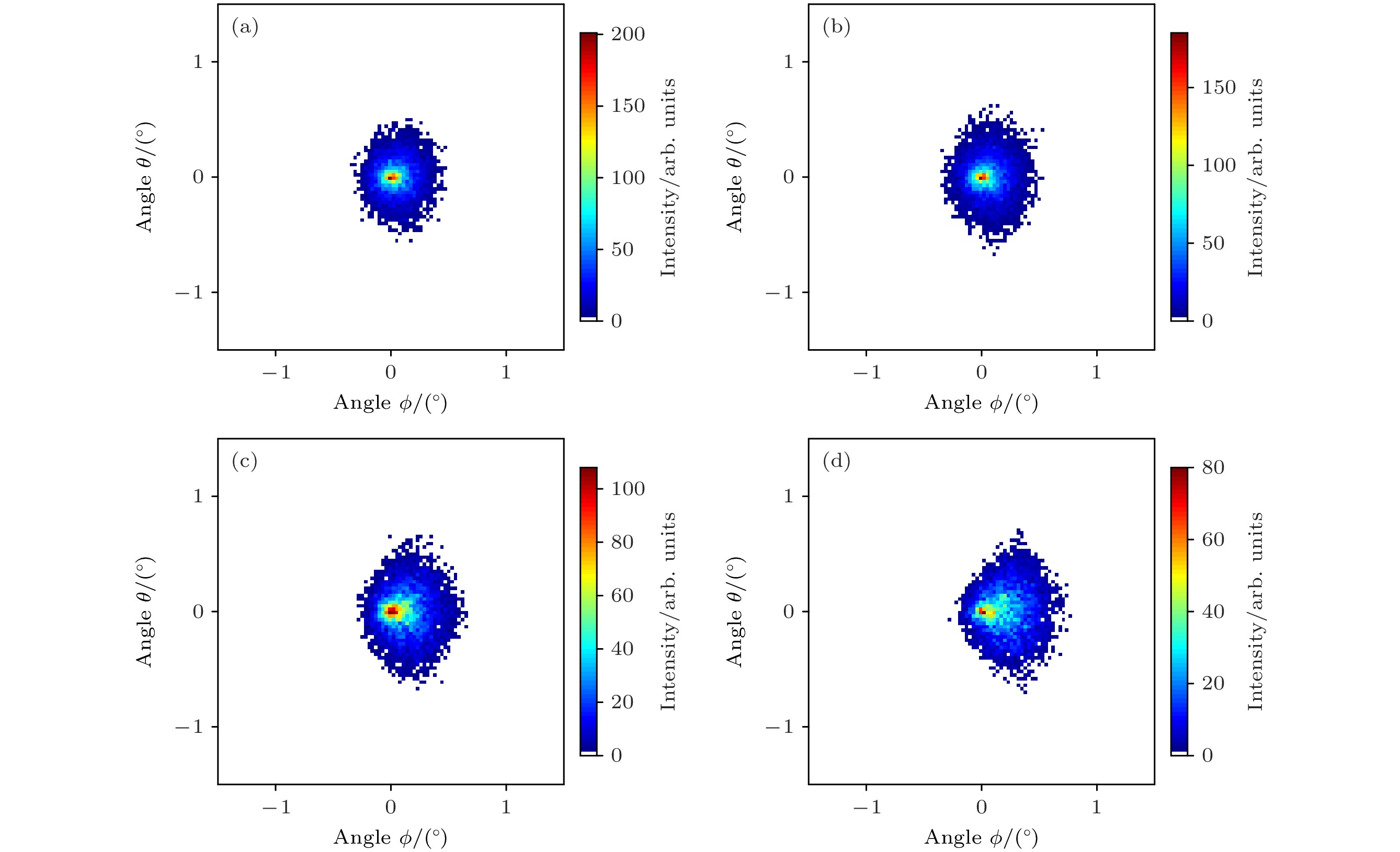
图 10 模拟计算倾角α = 0.1°, 束流发散度为(a) 0.7°和(b) 2.6°时三阶动态镜像电荷力下1 keV $ {\text{N}}_2^ + $离子穿越白云母微孔膜的出射离子二维角分布; 束流发散度为1.3°, 倾角为(c) 0.2°和(d) 0.3°时三阶动态镜像电荷力下1 keV $ {\text{N}}_2^ + $离子穿越白云母微孔膜的出射离子二维角分布
Figure 10. Simulated two-dimensional angular distributions of 1 keV $ {\text{N}}_2^ + $ ions emerging from muscovite microporous membranes under the influence of third-order dynamic image charge force: (a) Beam divergence is 0.7° with an incident angle α of 0.1°; (b) beam divergence is 2.6° with an incident angle α of 0.1°; (c) beam divergence is 1.3° with an incident angle α of 0.2°; (d) beam divergence is 1.3° with an incident angle α of 0.3°.
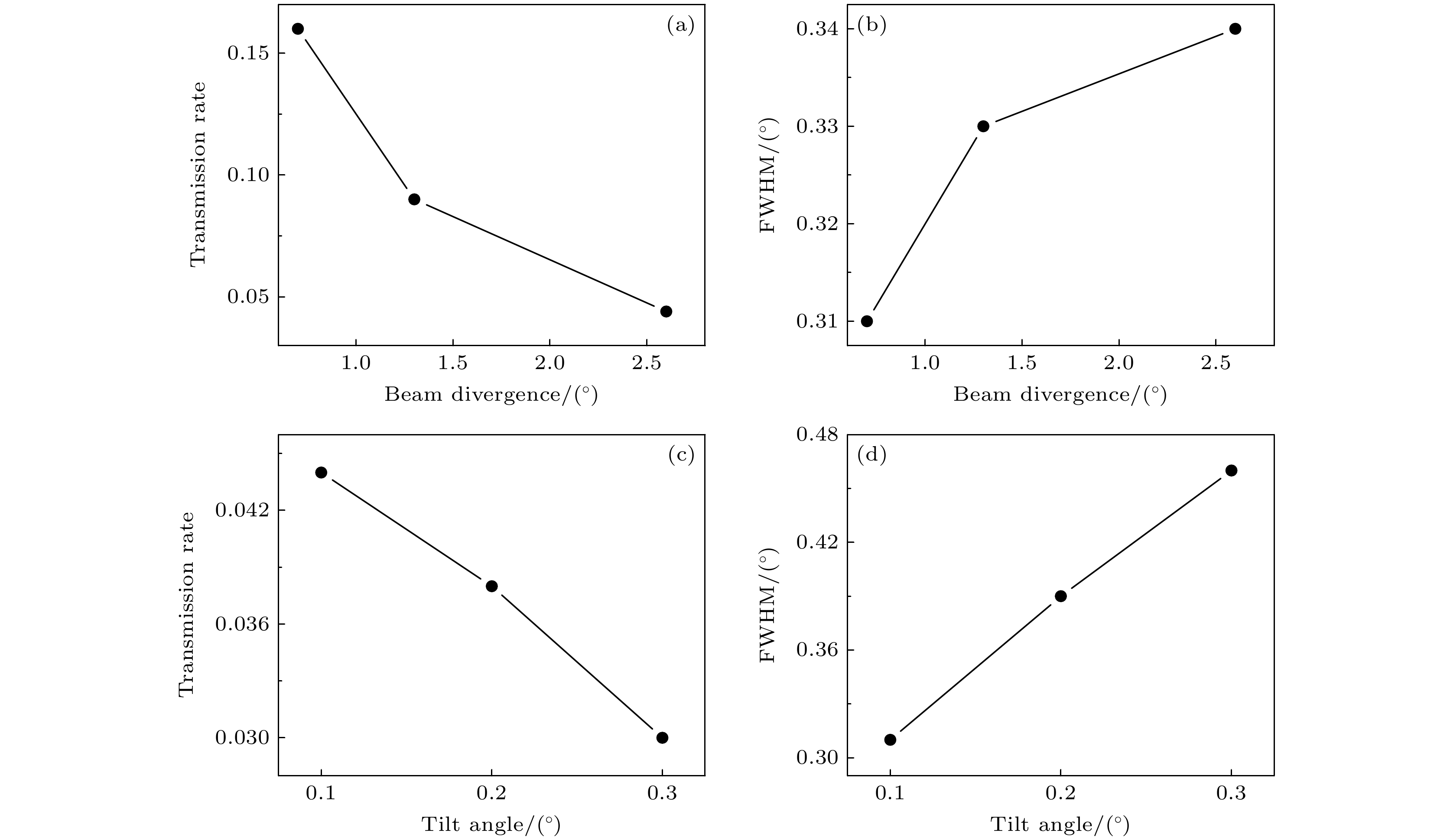
图 11 模拟计算倾角α = 0.1°, 束流发散度为0.7°, 1.3°和2.6°时1 keV $ {\text{N}}_2^ + $离子穿越纳米微孔在三阶动态镜像电荷力作用下的离子穿透率(a)和出射离子二维角分布的半高宽(b); 束流发散度为1.3°, 倾角α = 0.1°, 0.2°及0.3°时的离子穿透率(c)和角分布半高宽(d)
Figure 11. Simulated calculations of the ion transmission rate (a) and the full width at half maximum (FWHM) of the two-dimensional angular distribution of emitted ions (b) for 1 keV $ {\text{N}}_2^ + $ ions passing through nano-pores under the influence of third-order dynamic image charge force at incident angles α of 0.1° and beam divergences of 0.7°, 1.3°, and 2.6°. Ion transmission rate (c) and angular distribution FWHM (d) for beam divergence of 1.3° and incident angles α of 0.1°, 0.2°, and 0.3°.
-
[1] Spohr R, Bethge K 1990 Ion Tracks and Microtechnology (Wiesbaden: Vieweg Verlag) p1
[2] Martin C R 1994 Science 266 1961
 Google Scholar
[3] Stolterfoht N, Yamazaki Y 2016 Phys. Rep. 629 1
 Google Scholar
[4] Stolterfoht N, Bremer J H, Hoffmann V, Hellhammer R, Fink D, Petrov A, Sulik B 2002 Phys. Rev. Lett. 88 133201
 Google Scholar
[5] Zhang H Q, Akram N, Skog P, Soroka I L, Trautmann C, Schuch R 2012 Phys. Rev. Lett. 108 193202
 Google Scholar
[6] Iwai Y, Ikeda T, Kojima T M, Yamazaki Y, Maeshima K, Imamoto N, Kobayashi T, Nebiki T, Narusawa T, Pokhil G P 2008 Appl Phys. Lett. 92 023509
 Google Scholar
[7] Lemell C, Burgdörfer J, Aumayr F P 2013 Surf. Sci. 88 237
 Google Scholar
[8] Kanai Y, Hoshino M, Kambara T, Ikeda T, Hellhammer R, Stolterfoht N, Yamazaki Y 2009 Phys. Rev. A 79 012711
 Google Scholar
[9] Stolterfoht N 2013 Phys. Rev. A 87 012902
 Google Scholar
[10] Stolterfoht N 2013 Phys. Rev. A 87 032901
 Google Scholar
[11] Stolterfoht N, Hellhammer R, Juhász Z, et al. 2009 Phys. Rev. A 79 042902
 Google Scholar
[12] Rajendra-Kumar R T, Badel X, Vikor G, Linnros J, Schuch R 2005 Nanotechnology 16 1697
 Google Scholar
[13] Sahana M B, Skog P, Vikor G, Rajendra-Kumar R T, Schuch R 2006 Phys. Rev. A 73 040901
 Google Scholar
[14] Skog P, Zhang H Q, Schuch R 2008 Phys. Rev. Lett. 101 223202
 Google Scholar
[15] Zhang H Q, Skog P, Schuch R 2010 Phys. Rev. A 82 052901
 Google Scholar
[16] Mátéfi-Tempfli S, Mátéfi-Tempfli M, Piraux L, et al. 2006 Nanotechnology 17 3915
 Google Scholar
[17] Krause H F, Vane C R, Meyer F W 2007 Phys. Rev. A 75 042901
 Google Scholar
[18] Skog P, Soroka I L, Johansson A, Schuch R 2007 Nucl. Instrum. Methods Phys. Res., Sect. B 258 145
 Google Scholar
[19] Juhász Z, Sulik B, Biri S, et al. 2009 Nucl. Instrum. Methods Phys. Res., Sect. B 267 321
 Google Scholar
[20] Li D, Wang Y, Zhao Y, Xiao G, Zhao D, Xu Z, Li F 2009 Nucl. Instrum. Methods Phys. Res., Sect. B 267 469
 Google Scholar
[21] Stolterfoht N, Hellhammer R, Sulik B, et al. 2011 Phys. Rev. A 83 062901
 Google Scholar
[22] Schiessl K, Palfinger W, Tökési K, Nowotny H, Lemell C, Burgdörfer J 2005 Phys. Rev. A 72 062902
 Google Scholar
[23] Schiessl K, Palfinger W, Tökési K, Nowotny H, Lemell C, Burgdörfer J 2007 Nucl. Instrum. Methods Phys. Res. , Sect. B 258 150
 Google Scholar
[24] 李鹏飞, 袁华, 程紫东, 钱立冰, 刘中林, 靳博, 哈帅, 张浩文, 万城亮, 崔莹, 马越, 杨治虎, 路迪, Reinhold Schuch, 黎明, 张红强, 陈熙萌 2022 71 084104
 Google Scholar
Li P F, Yuan H, Cheng Z D, Qian L B, Liu Z L, Jin B, Ha S, Zhang H W, Wan C L, Cui Y, Ma Y, Yang Z H, Lu D, Schuch R, Li M, Zhang H Q, Chen X M 2022 Acta Phys. Sin. 71 084104
 Google Scholar
[25] 李鹏飞, 袁华, 程紫东, 钱立冰, 刘中林, 靳博, 哈帅, 万城亮, 崔莹, 马越, 杨治虎, 路迪, Reinhold Schuch, 黎明, 张红强, 陈熙萌 2022 71 074101
 Google Scholar
Li P F, Yuan H, Cheng Z D, Qian L B, Liu Z L, Jin B, Ha S, Wan C L, Cui Y, Ma Y, Yang Z H, Lu D, Schuch R, Li M, Zhang H Q, Chen X M 2022 Acta Phys. Sin. 71 074101
 Google Scholar
[26] 万城亮, 潘俞舟, 朱丽萍, 李鹏飞, 张浩文, 赵卓彦, 袁华, 樊栩宏, 孙文胜, 杜战辉, 陈乾, 崔莹, 廖天发, 魏晓慧, 王天琦, 陈熙萌, 李公平, Reinhold Schuch, 张红强 2024 73 104101
 Google Scholar
Wan C L, Pan Y Z, ZHU L P, Zhang H W, Zhao Z Y, Yuan H, Liu P F, Fan X H, Sun W S, DU Z H, Chen Q, Cui Y, Liao T F, Wei X H, Wang T Q, Chen X M, Li G P, Schuch R, Zhang H Q 2024 Acta Phys. Sin. 73 104101
 Google Scholar
[27] Pokhil G P, Vokhmyanina K A 2008 J. Surf. Invest. 2 p237
 Google Scholar
[28] Zhang H Q, Akram N, Soroka I L, Trautmann C, Schuch R 2012 Phys. Rev. A 86 022901
 Google Scholar
[29] Zhang H Q, Akram N, Schuch R 2016 Phys. Rev. A 94 032704
 Google Scholar
[30] Harris J, Jones R O 1974 J. Phys. C: Solid State Phys. 7 3751
 Google Scholar
[31] Wiza J L 1979 Nucl. Instrum. Methods. 162 587
 Google Scholar
[32] Lampton M, Carlson C W 1979 Rev. Sci. Instrum. 50 1093
 Google Scholar
[33] FASTER http://faster.in2p3.fr/
[34] Ackermann J, Angert N, Neumann R, Trautmann C, Dischner M, Hagen T, Sedlacek M 1996 Nucl. Instrum. Methods Phys. Res. , Sect. B 107 181
 Google Scholar
[35] Ward A A 2016 ResearchGate 2 10
 Google Scholar
[36] Giglio E 2023 Phys. Rev. A. 107 012816
 Google Scholar
[37] Petzelt J, Rychetský I 2005 Dielectric function, Encyclopedia of Condensed Matter Physics (Amsterdam: Elsevier) p426
[38] Beran A 2002 Rev. Mineral. Geochem. 46 351
 Google Scholar
[39] Fali A, Gamage S, Howard M, et al. 2021 ACS Photonics 8 175
 Google Scholar
[40] Agostinelli S, Allison J R, Amako K, et al. 2003 Nucl. Instrum. Methods Phys. Res., Sect. A 506 250
 Google Scholar
[41] Zhang Q, Liu Z L, Li P F, et al. 2018 Phys. Rev. A 97 042704
 Google Scholar
Catalog
Metrics
- Abstract views: 1160
- PDF Downloads: 52
- Cited By: 0


 DownLoad:
