-
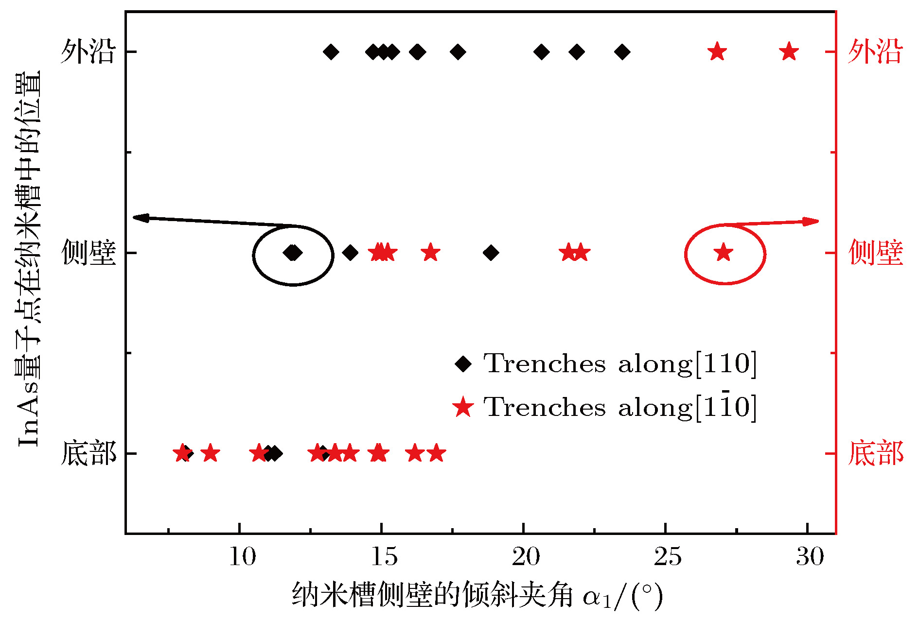
InAs/GaAs quantum dot (QD) is one of the promising material systems for the quantum information processing due to their atomic-like optical and electrical properties. There are many previous researches reporting the InAs QDs which can be implemented as solid-state single-photon sources for quantum information and quantum computing. However, the site-controlled growth of QDs is the prerequisite for addressability and integration. There are very few researches focusing on the systematic study of preferential nucleation of InAs QDs on a patterned GaAs (001) substrate. In this work, we study the preferential nucleation sites of InAs QDs on a patterned GaAs (001) substrate with different trench sidewall inclinations. With small inclination angle of the trench sidewalls, the InAs QDs nucleate preferentially inside the trenches, while with large inclination angle, the edges of the trenches appear to be the preferential nucleation sites. By utilizing the established method, a pair of InAs dots can be uniformly achieved in the patterned pits through tuning the inclination angle of the pits. The site-controlled single InAs QD and InAs QD molecules on the patterned substrates could have potential applications in quantum information processing and quantum computing.
-
Keywords:
- InAs quantum dots /
- patterned substrate /
- nucleation site /
- site-controlled growth
[1] Liu H Y, Wang T, Jiang Q, Hogg R, Tutu F, Pozzi F, Seeds A 2011 Nat. Photonics 5 416
 Google Scholar
[2] Liu H Y, Xu B, Wei Y Q, Ding D, Qian J J, Han Q, Liang J B, Wang Z G 2001 Appl. Phys. Lett. 79 2868
 Google Scholar
[3] Sanjay K 2005 J. Phys. D: Appl. Phys. 38 2142
 Google Scholar
[4] Cerulo G, Liverini V, Fedoryshyn Y, Faist J 2017 Appl. Phys. Lett. 110 091106
 Google Scholar
[5] Yamaguchi M, Nishimura K, Sasaki T, Suzuki H, Arafune K, Kojima N, Ohsita Y, Okada Y, Yamamoto A, Takamoto T, Araki K 2008 Sol. Energy 82 173
 Google Scholar
[6] Tanabe K, Watanabe K, Arakawa Y 2012 Appl. Phys. Lett. 100 192102
 Google Scholar
[7] Rakhlin M V, Belyaev K G, Klimko G V, Mukhin I S, Kirilenko D A, Shubina T V, Ivanov S V, Toropov A A 2018 Sci. Rep. 8 5299
 Google Scholar
[8] Maier S, Berschneider K, Steinl T, Forchel A, Höfling S, Schneider C, Kamp M 2014 Semicond. Sci. Technol. 29 052001
 Google Scholar
[9] Weng Q C, An Z H, Zhu Z Q, Song J D, Choi W J 2014 Appl. Phys. Lett. 104 051113
 Google Scholar
[10] Fattal D, Diamanti E, Inoue K, Yamamoto Y 2004 Phys. Rev. Lett. 92 037904
 Google Scholar
[11] Waks E, Inoue K, Santori C, Fattal D, Vuckovic J, Solomon G S, Yamamoto Y 2002 Nature 420 762
 Google Scholar
[12] Tougaw P D, Lent C S 1994 J. Appl. Phys. 75 1818
 Google Scholar
[13] Timler J, Lent C S 2002 J. Appl. Phys. 91 823
 Google Scholar
[14] Ishikawa T, Kohmoto S, Asakawa K 1998 Appl. Phys. Lett. 73 1712
 Google Scholar
[15] Atkinson P, Kiravittaya S, Benyoucef M, Rastelli A, Schmidt O G 2008 Appl. Phys. Lett. 93 101908
 Google Scholar
[16] Vastola G, Grydlik M, Brehm M, Fromherz T, Bauer G, Boioli F, Miglio L, Montalenti F 2011 Phys. Rev. B 84 155415
 Google Scholar
[17] Hu H, Gao H J, Liu F 2008 Phys. Rev. Lett. 101 216102
 Google Scholar
[18] Kiravittaya S, Heidemeyer H, Schmidt O G 2004 Physica. E 23 253
 Google Scholar
[19] Horikoshi Y, Kawashima M, Yamaguchi H 1988 Jpn. J. Appl. Phys. 27 169
[20] Yamada T, Horikoshi Y 1994 Jpn. J. Appl. Phys. 33 1027
[21] Heidemeyer H, Muller C, Schmidt O G 2004 J. Cryst. Growth 261 444
 Google Scholar
[22] Costantini G, Rastelli A, Manzano C, Songmuang R, Schmidt O G, Kern K 2004 Appl. Phys. Lett. 85 5673
 Google Scholar
[23] Hata M, Isu T, Watanabe A, Katayama Y 1990 J. Vac. Sci. Technol. B 8 692
[24] Shen X Q, Nishinaga T 1993 Jpn. J. Appl. Phys. 32 L1117
 Google Scholar
-
图 1 GaAs (001)衬底与沿
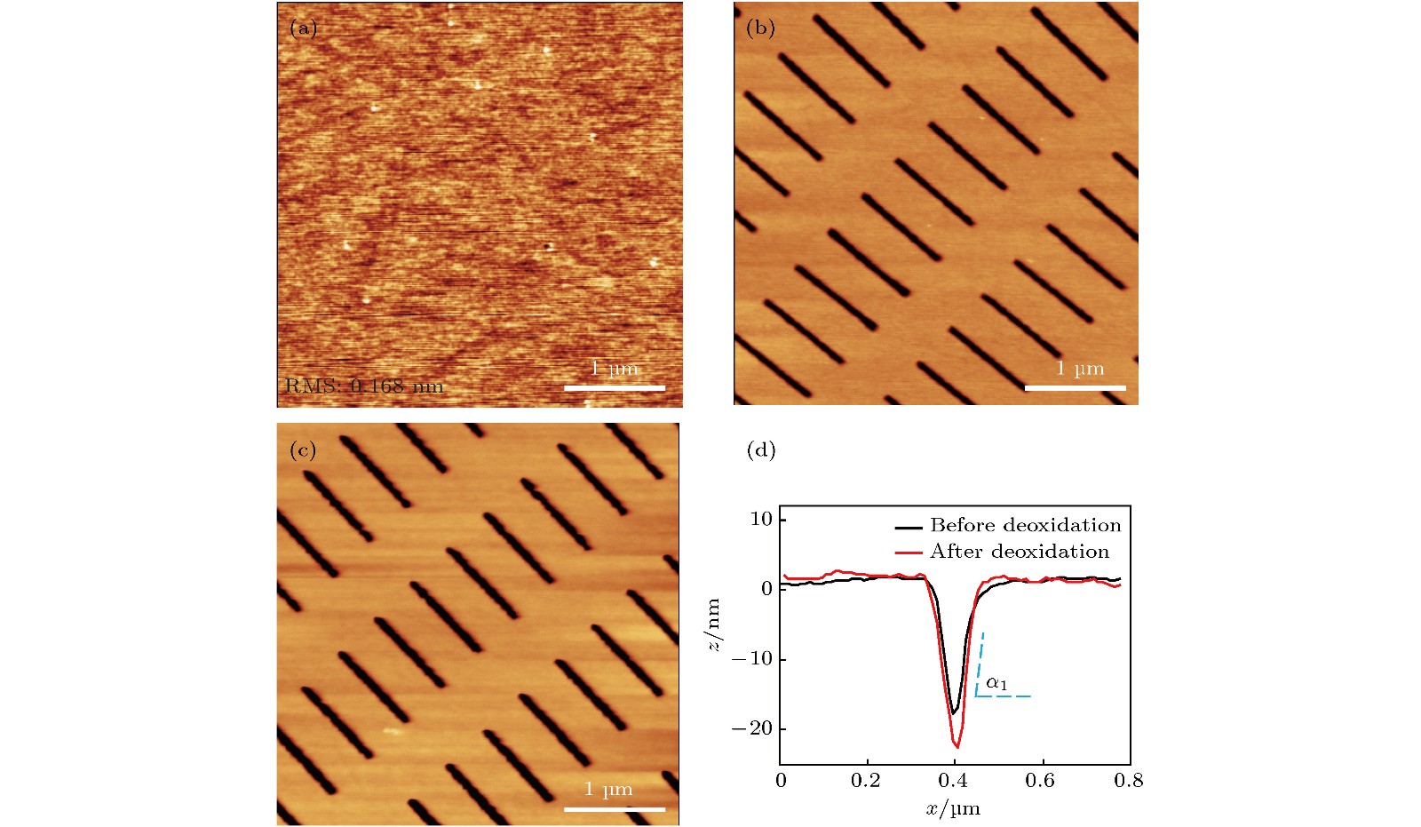
$\left[ {1\bar 10} \right]$ 方向的纳米沟槽脱氧前后的形貌变化 (a)脱氧后平衬底区域的AFM图; (b), (c) α1 ≈ 16°时图形结构区域脱氧前后的AFM图; (d)沟槽脱氧前后AFM线扫描图Figure 1. Morphological change of patterned GaAs (001) substrate before and after deoxidation: (a) AFM image of flat GaAs after deoxidation; AFM image of patterned GaAs before (b) and after deoxidation (c), the trenches are orientated along
$\left[ {1\bar 10} \right]$ direction and the sidewall inclination angle α1 is about 16°; (d) AFM line-scans of the trenches before (black line) and after deoxidation (red line).图 2 沿
$\left[ {1\bar 10} \right]$ 方向倾斜角α1 ≈ 40°时的纳米沟槽在GaAs缓冲层生长前后的形貌变化 (a), (b)低温外延30 nm GaAs缓冲层前后的AFM图; (c)生长前后沟槽的AFM线扫描图, 图中黑色曲线对应α1 ≈ 40°, 红色曲线对应α1 ≈ 39°, α2 ≈ 19°Figure 2. Morphological change of the trenches (inclination angle α1 ≈ 40° and orientated along
$\left[ {1\bar 10} \right]$ direction) after GaAs buffer growth: (a), (b) AFM images of the trenches before and after the deposition of 30 nm GaAs buffer at low temperature; (c) the black and red lines represent the cross-sectional AFM line-scans of (a) and (b). α1 ≈ 40° (black line); α1 ≈ 39°, α2 ≈ 19° (red line).图 5 InAs QDs优先成核位置在相同倾斜角度不同方向的纳米沟槽中的各向异性 (a)和(b)分别为α1≈18°时沿
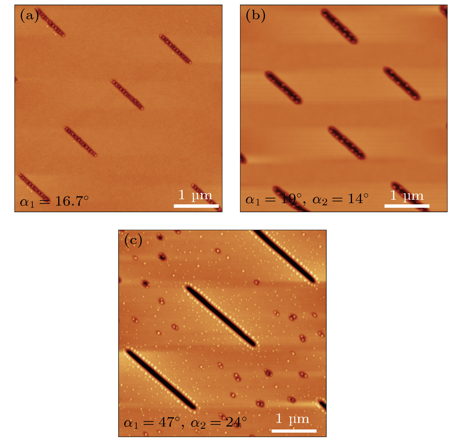
$\left[ {1\bar 10} \right]$ 和[110]方向纳米沟槽生长InAs量子点后的AFM图Figure 5. Orientational dependence of InAs QDs on trench-patterned GaAs along
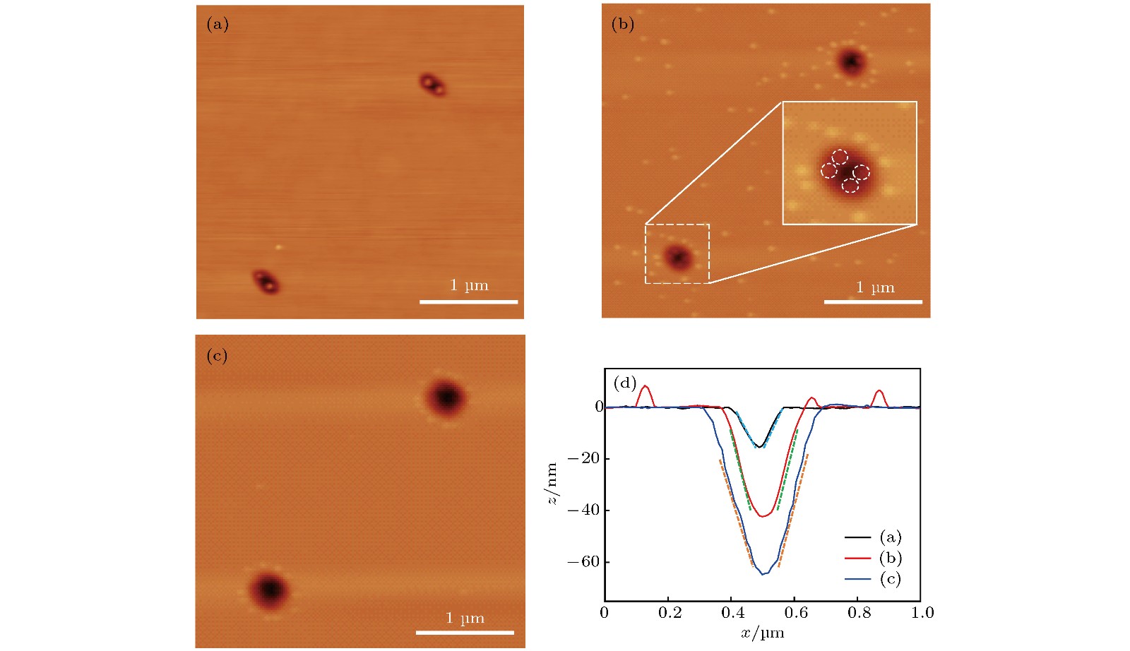
$\left[ {1\bar 10} \right]$ and [110]: (a) and (b) AFM images of InAs QDs grown on trench-patterned GaAs along$\left[ {1\bar 10} \right]$ and [110] with a trench inclination angle α1 ≈ 18°.图 6 调控纳米孔洞侧壁的倾斜角α1实现不同InAs量子点组合的定位生长 (a)生长在纳米孔洞底部的双量子点分子; (b)生长在纳米沟槽侧壁上的四量子点, 其中插图示意四量子点的位置; (c)纳米孔洞外沿形成量子点环; (d)图(a), (b)和(c)中纳米孔洞的AFM线扫描图, 倾斜角分别为10°, 17°, 28°
Figure 6. Site-controlled growth of InAs QDs molecules on pit-patterned GaAs (001) substrate: (a) Double InAs QDs molecules at the pits bottom; (b) four InAs QDs molecules in the pits; (c) QDs rings around the pits; (d) cross-sectional AFM line-scan of these pits. The inclination angles are 10°, 17°, 28°, respectively.
-
[1] Liu H Y, Wang T, Jiang Q, Hogg R, Tutu F, Pozzi F, Seeds A 2011 Nat. Photonics 5 416
 Google Scholar
[2] Liu H Y, Xu B, Wei Y Q, Ding D, Qian J J, Han Q, Liang J B, Wang Z G 2001 Appl. Phys. Lett. 79 2868
 Google Scholar
[3] Sanjay K 2005 J. Phys. D: Appl. Phys. 38 2142
 Google Scholar
[4] Cerulo G, Liverini V, Fedoryshyn Y, Faist J 2017 Appl. Phys. Lett. 110 091106
 Google Scholar
[5] Yamaguchi M, Nishimura K, Sasaki T, Suzuki H, Arafune K, Kojima N, Ohsita Y, Okada Y, Yamamoto A, Takamoto T, Araki K 2008 Sol. Energy 82 173
 Google Scholar
[6] Tanabe K, Watanabe K, Arakawa Y 2012 Appl. Phys. Lett. 100 192102
 Google Scholar
[7] Rakhlin M V, Belyaev K G, Klimko G V, Mukhin I S, Kirilenko D A, Shubina T V, Ivanov S V, Toropov A A 2018 Sci. Rep. 8 5299
 Google Scholar
[8] Maier S, Berschneider K, Steinl T, Forchel A, Höfling S, Schneider C, Kamp M 2014 Semicond. Sci. Technol. 29 052001
 Google Scholar
[9] Weng Q C, An Z H, Zhu Z Q, Song J D, Choi W J 2014 Appl. Phys. Lett. 104 051113
 Google Scholar
[10] Fattal D, Diamanti E, Inoue K, Yamamoto Y 2004 Phys. Rev. Lett. 92 037904
 Google Scholar
[11] Waks E, Inoue K, Santori C, Fattal D, Vuckovic J, Solomon G S, Yamamoto Y 2002 Nature 420 762
 Google Scholar
[12] Tougaw P D, Lent C S 1994 J. Appl. Phys. 75 1818
 Google Scholar
[13] Timler J, Lent C S 2002 J. Appl. Phys. 91 823
 Google Scholar
[14] Ishikawa T, Kohmoto S, Asakawa K 1998 Appl. Phys. Lett. 73 1712
 Google Scholar
[15] Atkinson P, Kiravittaya S, Benyoucef M, Rastelli A, Schmidt O G 2008 Appl. Phys. Lett. 93 101908
 Google Scholar
[16] Vastola G, Grydlik M, Brehm M, Fromherz T, Bauer G, Boioli F, Miglio L, Montalenti F 2011 Phys. Rev. B 84 155415
 Google Scholar
[17] Hu H, Gao H J, Liu F 2008 Phys. Rev. Lett. 101 216102
 Google Scholar
[18] Kiravittaya S, Heidemeyer H, Schmidt O G 2004 Physica. E 23 253
 Google Scholar
[19] Horikoshi Y, Kawashima M, Yamaguchi H 1988 Jpn. J. Appl. Phys. 27 169
[20] Yamada T, Horikoshi Y 1994 Jpn. J. Appl. Phys. 33 1027
[21] Heidemeyer H, Muller C, Schmidt O G 2004 J. Cryst. Growth 261 444
 Google Scholar
[22] Costantini G, Rastelli A, Manzano C, Songmuang R, Schmidt O G, Kern K 2004 Appl. Phys. Lett. 85 5673
 Google Scholar
[23] Hata M, Isu T, Watanabe A, Katayama Y 1990 J. Vac. Sci. Technol. B 8 692
[24] Shen X Q, Nishinaga T 1993 Jpn. J. Appl. Phys. 32 L1117
 Google Scholar
Catalog
Metrics
- Abstract views: 10615
- PDF Downloads: 136
- Cited By: 0


 DownLoad:


