-
Frequency selective surface (FSS) is of great research interest for its wide applications in radome, absorber, electromagnetic filters, and artificial electromagnetic bandgap materials. In order to achieve a multifunctional FSS with real-time manipulated radar cross-section (RCS), there are mainly three ways, i.e. to design reconfigurable FSS unit cell, reconfigurable screen, and a combination of reconfigurable unit cell and screen. In this work, a combination design of both the reconfigurable unit cells and FSS screen is proposed to realize a dual-band FSS absorber with real-time manipulated RCS. For the reconfigurable unit cell, an angular ring and a meander cross dipole are combined to obtain a dual-band absorption. The dual-band resonance frequencies are reconfigurable by switching the PIN diodes embedded in the unit cell. When switching the PIN diodes, the resonance frequencies of the unit cell would be changed due to the variation of the effective capacitance and inductance of the unit cell. For the reconfigurable FSS screen, a novel biasing network is introduced, then the scattering field from each unit cell is modulated independently by switching the “on/off” state of the PIN diode through using a programmable field programmable gate array (FPGA). The total scattering far field is expressed as the superposition of the scattering field from each unit cell, and the far field scattered by the unit cell which is evaluated under an infinite periodic boundary condition. The scattering field of the FSS absorber can be predicted by considering the working states of all the unit cells on the screen. We define the unit cell as state “0”, when all the PIN diodes are at the states of “off”, and as state “1” when the PIN diodes are all at the states of “off”. The entire screen of FSS absorber is thus pixelated, which can be expressed by a binary coding matrix. The real-time scattering fields from the FSS absorber are manipulated perfectly by optimizing the states matrices showing “on/off” of each unit cell with genetic algorithm (GA). The FSS absorber is fabricated and measured. The ranges of 33dB and 25dB reconfigurable monostatic RCS at 3.2 GHz and 10.3 GHz are achieved by coding the states of unit cells on the FSS absorber screen. Both full-wave and analytical simulations demonstrate the effectiveness of the proposed optimization procedure. Compared with the reported FSS absorber, the proposed design is validated to possess good performance.
-
Keywords:
- frequency selective surfaces /
- absorber /
- radar cross section /
- reconfigurable
[1] Munk B A 2020 Frequency Selective Surfaces: Theory and Design (New York: Wiley) pp5–25
[2] Wu T K Ed 1995 Frequency Selective Surface and Grid Array (New York: Wiley) pp5–25
[3] Kern D J, Werner D H 2003 Microwave Opt. Technol. Lett. 38 61
[4] Bossard J A, Werner D H, Mayer T S, Drupp R P 2005 IEEE Trans. Antennas Propag. 53 1390
[5] Costa F, Monorchio A 2012 IEEE Trans. Antennas Propag. 60 2740
[6] Ghosh S, Srivastava K V 2017 IEEE Antennas Wireless Propag. Lett. 16 1687
[7] Ghosh S, Srivastava K V 2014 IEEE Antennas Wireless Propag. Lett. 14 511
[8] Tennant A, Chambers B 2004 IEEE Microw. Wireless Compon. Lett. 14 46
[9] Sun L, Cheng H, Zhou Y, Wang J 2012 Optics Express 20 4675
 Google Scholar
[10] 吴晨骏, 程用志, 王文颖, 何博, 龚荣洲 2015 64 164102
 Google Scholar
Wu C J, Cheng Y Z., Wang W Y, He B, Gong R Z 2015 Acta Phys. Sin. 64 164102
 Google Scholar
[11] 李勇峰, 张介秋, 屈绍波, 王甲富, 陈红雅, 徐卓, 张安学 2014 63 084103
 Google Scholar
Li Y F, Zhang J Q, Qu S B, Wang J F, Chen H Y, Xu Z, Zhang A X 2014 Acta Phys. Sin. 63 084103
 Google Scholar
[12] 张银, 冯一军, 姜田, 曹杰, 赵俊明, 朱博 2017 66 204101
 Google Scholar
Zhang Y, Feng Y J, Jiang T, Cao J, Zhao J M, Zhu B 2017 Acta Phys. Sin. 66 204101
 Google Scholar
[13] Costantine J, Tawk Y, Barbin S E, Christodoulou C G 2015 Proc. IEEE 103 424
 Google Scholar
[14] Zhu B, Huang C, Feng Y, Zhao J, Jiang T 2010 Prog. Electromagn. 24 121
 Google Scholar
[15] Xu W, Sonkusale S 2013 Appl. Phys. Lett. 103 031902
 Google Scholar
[16] WangM, Hu C, Pu M, Huang C, Ma X, Luo X 2012 Electron. Lett. 48 1002
[17] Xu W, He Y, Kong P, Li J, Xu H, Miao L, Bie S, Jiang J 2015 J. Appl. Phys. 118 184903
 Google Scholar
[18] Parker E A, Savia S B 2001 in Proc. Inst. Elect. Eng. Microwaves, Antennas, Propag. 148 103
 Google Scholar
[19] Lima A C de C, Parker E A, Langley R J 1994 Electron. Lett. 30 281
 Google Scholar
[20] Cui T J, Qi M Q, Wan X, Zhao J, Cheng Q 2014 Light Sci. Appl. 3 e218
[21] Li M, Li S, Yu Y F, Ni X, Chen R S 2018 Opt. Express 26 24702
 Google Scholar
[22] Pazokian M, Komjani N, Karimipour M 2018 IEEE Antennas Wireless Propag. Lett. 17 1382
 Google Scholar
[23] Liu X, Gao J, Xu L, Cao X, Zhao Y, Li S 2016 IEEE Antennas Wireless Propag. Lett. 16 724
[24] Yu J, Jiang W, Gong S 2019 IEEE Antennas Wireless Propag. Lett. 18 2016
 Google Scholar
[25] Jia Y, Liu Y, Guo Y J, Li K, Gong S X 2016 IEEE Trans. Antennas Propag. 64 179
 Google Scholar
[26] Liu Y, Li K, Jia Y, Hao Y, Gong S X, Guo Y J 2016 IEEE Trans.Antennas Propag. 64 326
 Google Scholar
[27] Yang H, Yang F, Xu S, Mao Y, Li M, Cao X, Gao J 2016 IEEE Trans.Antennas Propag. 64 2246
 Google Scholar
[28] Yang H, Yang F, Cao X, Xu S, Gao J, Chen X, Li M, Li T 2017 IEEE Trans.Antennas Propag. 65 3024
 Google Scholar
[29] Xu J, Li M, Chen R S 2017 IET Microwaves Antennas Propag. 11 1578
-
图 3 单元二极管全“截止”状态时表面电流分布 (a) 3.9 GHz, (b) 10.6 GHz; 单元二极管全“导通”状态时表面电流分布 (c) 3.9 GHz, (d) 10.6 GHz
Figure 3. Surface currents distribution of the FSS unit cell with PIN diodes all at “off” states at (a) 3.9 GHz and (b) 10.6 GHz; surface currents distribution of the FSS unit cell with PIN diodes all at “on” states at (c) 3.9 GHz and (d) 10.6 GHz.
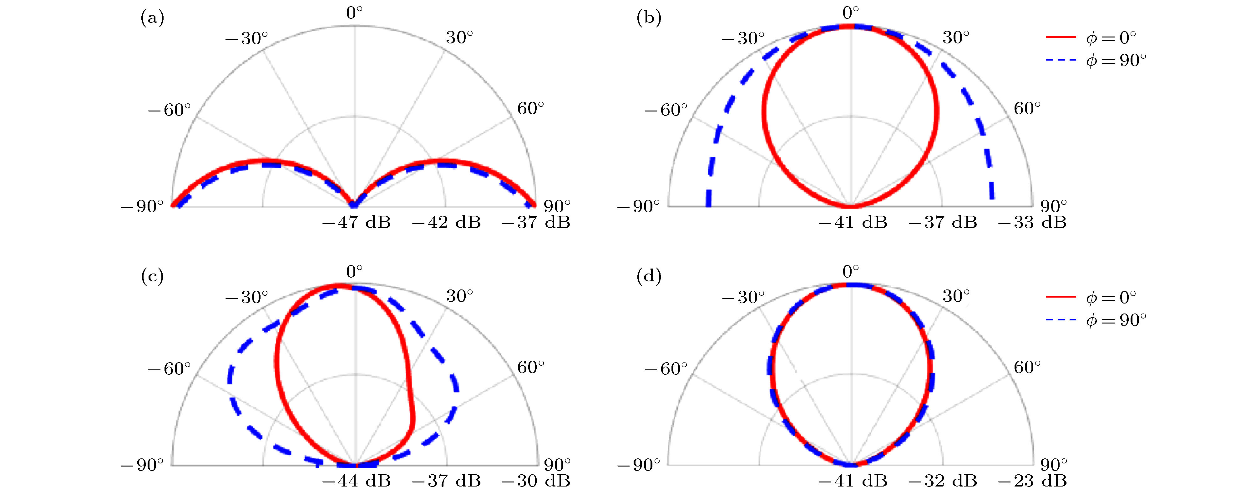
图 4 单元的二极管全“截止”状态时频率为 (a) 3.9 GHz, (c) 10.6 GHz的RCS; 单元的二极管全“导通”状态时频率为 (b) 3.9 GHz, (d) 10.6 GHz的RCS
Figure 4. Simulated two-dimensional RCS of the FSS unit cell with PIN diodes all at “off” states at (a) 3.9 GHz and (c) 10.6 GHz; two-dimensional RCS when with PIN diodes all at “on” states at (b) 3.9 GHz and (d) 10.6 GHz.
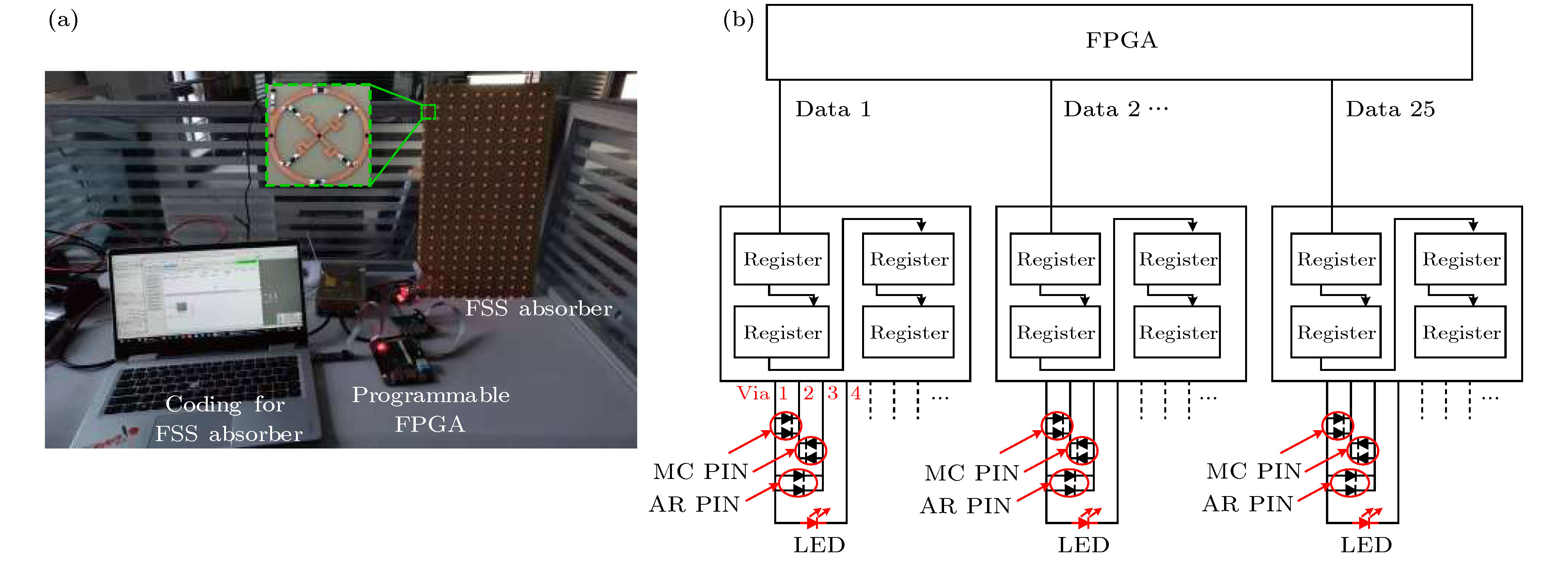
图 5 RCS实时可调的FSS吸波器 (a) 可重构FSS吸波器系统包括FSS吸波器, FPGA, 状态编码的PIN开关; (b) 偏置网络
Figure 5. Reconfigurable FSS absorber with real-time coding RCS: (a) System of the reconfigurable FSS absorber including FSS absorber, programmable FPGA, and coding for the states of switchable PIN diodes, inset is a fabricated unit cell; (b) biasing network for PIN diodes embedded in the meander cross (MC) and angular ring (AR) of the unit cells.
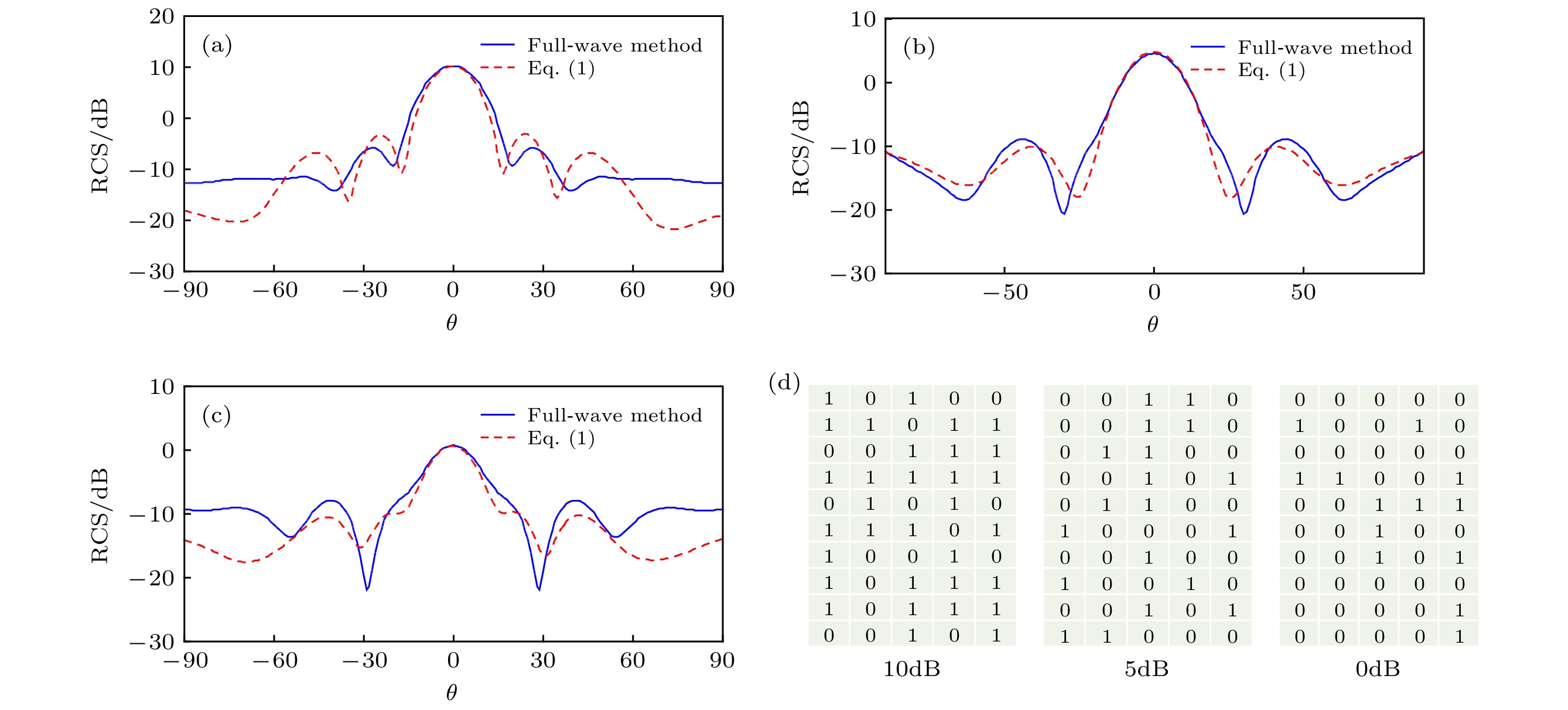
图 6 在3.8 GHz频率下双站RCS的全波仿真结果, 当优化1/4阵列的状态矩阵时, 主反射方向
$(\theta ={0^ \circ }, \phi = {0^ \circ })$ 的RCS为 (a) 10dB, (b) 5dB, (c) 0dB, (d) 1/4阵列的优化状态Figure 6. Full-wave and analytical method simulated bistatic RCS of the reconfigurable FSS absorber at 3.8 GHz. The RCS is manipulated to be (a) 10dB, (b) 5dB, and (c) 0dB at the main reflection direction
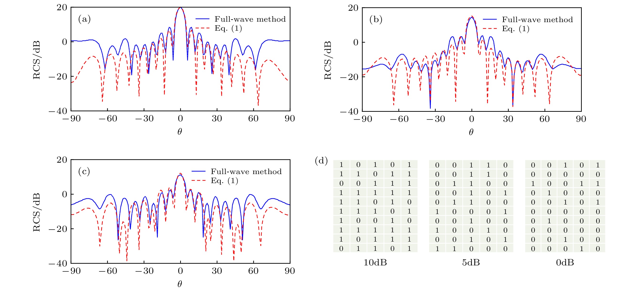
$(\theta ={0^ \circ }, \phi = {0^ \circ })$ , when optimizing the states matrices as in (d) of the unit cells of a quarter of the screen.图 7 在10.5 GHz频率下双站RCS的全波仿真结果, 当优化1/4阵列的状态矩阵时, 主反射方向
$(\theta ={0^ \circ }, \phi = {0^ \circ })$ 的RCS为 (a) 20dB, (b) 15dB, (c) 10dB, (d) 1/4阵列的优化状态Figure 7. Full-wave and analytical method simulated bistatic RCS of the reconfigurable FSS absorber at 10.5 GHz. The RCS is manipulated to be (a) 20dB (b) 15dB, and (c) 10dB at the main reflection direction
$(\theta ={0^ \circ }, \phi = {0^ \circ })$ , when optimizing the states matrices as in (d) of the unit cells of a quarter of the screen.图 8 双站RCS全波仿真结果. 当优化1/4阵列的状态矩阵时, 主反射方向
$(\theta ={0^ \circ }, \phi = {0^ \circ })$ 的RCS在3.8 GHz频率下为 (a) 10 dB, (b) 5 dB, (c) 0 dB; 在10.5 GHz频率下为 (d) 20 dB, (e) 15 dB, (f) 10 dBFigure 8. Full-wave simulated two-dimensional RCS of the reconfigurable FSS absorber. The RCS from the main reflection direction
$(\theta ={0^ \circ }, \phi = {0^ \circ })$ is optimized to be (a) 10 dB, (b) 5 dB, and (c) 0 dB at 3.8 GHz; the RCS is optimized to be (d) 20 dB, (e) 15 dB, and (f) 10 dB at 10.5 GHz.表 1 通孔1, 2, 3, 4的电压变化, 可重新配置FSS的吸波器状态
Table 1. Reconfigurable FSS based absorber unit cell with the change of the voltage of via holes 1, 2, 3, and 4.
状态 通孔1 通孔2 通孔3 通孔4 圆环 偶极子 LED 1 高 高 低 高 通 断 灭 2 高 低 高 高 断 通 灭 3 高 低 低 高 通 通 灭 4 低 低 低 高 断 断 亮 表 2 与现有可重构基于FSS的吸波器的比较
Table 2. Lists of the comparison with existing published reconfigurable FSS based absorber.
可重构吸波器 带宽个数 频率范围/GHz 厚度(${\lambda _0}$) 大小(${\lambda _0}$) RCS可调节范围/dB 能否调控RCS [6] 2 2.26, 3.79
4.02, 6.360.02 2.08 × 2.08 –16 否 [11] 1 2.60, 2.90 0.02 2.7 × 2.9 — 否 [12] 1 4.10, 4.79 0.05 2.4 × 1.1 –25 否 [13] 1 1.95, 2.07 0.02 3.2 × 3.2 –40 否 [14] 1 0.70, 0.90, 1.10, 1.40, 1.50, 1.80 0.03 2.0 × 2.0 –10 否 [19] 1 8.80 — 0.9 × 0.9 –24 否 本工作 2 3.20, 10.30
4.80, 11.000.08 12.5 × 6.25 3326 是 -
[1] Munk B A 2020 Frequency Selective Surfaces: Theory and Design (New York: Wiley) pp5–25
[2] Wu T K Ed 1995 Frequency Selective Surface and Grid Array (New York: Wiley) pp5–25
[3] Kern D J, Werner D H 2003 Microwave Opt. Technol. Lett. 38 61
[4] Bossard J A, Werner D H, Mayer T S, Drupp R P 2005 IEEE Trans. Antennas Propag. 53 1390
[5] Costa F, Monorchio A 2012 IEEE Trans. Antennas Propag. 60 2740
[6] Ghosh S, Srivastava K V 2017 IEEE Antennas Wireless Propag. Lett. 16 1687
[7] Ghosh S, Srivastava K V 2014 IEEE Antennas Wireless Propag. Lett. 14 511
[8] Tennant A, Chambers B 2004 IEEE Microw. Wireless Compon. Lett. 14 46
[9] Sun L, Cheng H, Zhou Y, Wang J 2012 Optics Express 20 4675
 Google Scholar
[10] 吴晨骏, 程用志, 王文颖, 何博, 龚荣洲 2015 64 164102
 Google Scholar
Wu C J, Cheng Y Z., Wang W Y, He B, Gong R Z 2015 Acta Phys. Sin. 64 164102
 Google Scholar
[11] 李勇峰, 张介秋, 屈绍波, 王甲富, 陈红雅, 徐卓, 张安学 2014 63 084103
 Google Scholar
Li Y F, Zhang J Q, Qu S B, Wang J F, Chen H Y, Xu Z, Zhang A X 2014 Acta Phys. Sin. 63 084103
 Google Scholar
[12] 张银, 冯一军, 姜田, 曹杰, 赵俊明, 朱博 2017 66 204101
 Google Scholar
Zhang Y, Feng Y J, Jiang T, Cao J, Zhao J M, Zhu B 2017 Acta Phys. Sin. 66 204101
 Google Scholar
[13] Costantine J, Tawk Y, Barbin S E, Christodoulou C G 2015 Proc. IEEE 103 424
 Google Scholar
[14] Zhu B, Huang C, Feng Y, Zhao J, Jiang T 2010 Prog. Electromagn. 24 121
 Google Scholar
[15] Xu W, Sonkusale S 2013 Appl. Phys. Lett. 103 031902
 Google Scholar
[16] WangM, Hu C, Pu M, Huang C, Ma X, Luo X 2012 Electron. Lett. 48 1002
[17] Xu W, He Y, Kong P, Li J, Xu H, Miao L, Bie S, Jiang J 2015 J. Appl. Phys. 118 184903
 Google Scholar
[18] Parker E A, Savia S B 2001 in Proc. Inst. Elect. Eng. Microwaves, Antennas, Propag. 148 103
 Google Scholar
[19] Lima A C de C, Parker E A, Langley R J 1994 Electron. Lett. 30 281
 Google Scholar
[20] Cui T J, Qi M Q, Wan X, Zhao J, Cheng Q 2014 Light Sci. Appl. 3 e218
[21] Li M, Li S, Yu Y F, Ni X, Chen R S 2018 Opt. Express 26 24702
 Google Scholar
[22] Pazokian M, Komjani N, Karimipour M 2018 IEEE Antennas Wireless Propag. Lett. 17 1382
 Google Scholar
[23] Liu X, Gao J, Xu L, Cao X, Zhao Y, Li S 2016 IEEE Antennas Wireless Propag. Lett. 16 724
[24] Yu J, Jiang W, Gong S 2019 IEEE Antennas Wireless Propag. Lett. 18 2016
 Google Scholar
[25] Jia Y, Liu Y, Guo Y J, Li K, Gong S X 2016 IEEE Trans. Antennas Propag. 64 179
 Google Scholar
[26] Liu Y, Li K, Jia Y, Hao Y, Gong S X, Guo Y J 2016 IEEE Trans.Antennas Propag. 64 326
 Google Scholar
[27] Yang H, Yang F, Xu S, Mao Y, Li M, Cao X, Gao J 2016 IEEE Trans.Antennas Propag. 64 2246
 Google Scholar
[28] Yang H, Yang F, Cao X, Xu S, Gao J, Chen X, Li M, Li T 2017 IEEE Trans.Antennas Propag. 65 3024
 Google Scholar
[29] Xu J, Li M, Chen R S 2017 IET Microwaves Antennas Propag. 11 1578
Catalog
Metrics
- Abstract views: 9965
- PDF Downloads: 201
- Cited By: 0


 DownLoad:


