


-
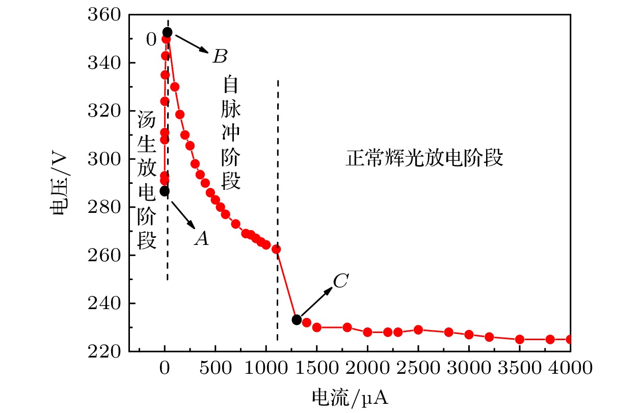
为了进一步揭示自脉冲放电机理, 本文对氩气环境下的微空心阴极自脉冲放电进行了实验研究. 结果表明, 随着放电电流的升高, 放电分为汤生放电、自脉冲放电和正常辉光放电三个阶段. 一个完整的自脉冲放电周期可以分为电流的上升期、下降期以及放电的等待期. 本文同时利用流体模型对自脉冲放电的时空动力学特性进行了模拟研究. 模拟结果表明, 当自脉冲放电电流处于最小值时, 放电被限制在阴极孔内, 电场强度、电子密度和电子产生速率均较低, 为汤生放电模式; 随着放电电流的增高, 孔内放电逐渐增强, 同时放电由孔内逐渐向孔外延伸. 当脉冲电流最高时, 阴极孔外具有较强的放电, 阴极外表面附近形成明显的阴极鞘层, 阴极腔外部存在较高的电子产生速率. 当放电电流降低时, 放电由孔外向孔内收缩, 并逐步恢复到汤生放电模式. 模拟结果同时表明, 不同自脉冲放电阶段电离源不同: 电流较高时直接电离起主要作用, 电流处于最低值时的脉冲等待期潘宁电离起主要作用. 实验和模拟结果表明, 微空心阴极自脉冲放电实质上是放电被限制在孔内的汤生放电模式与放电区域延伸到孔外的正常辉光放电模式相互转换的过程.To further explore the mechanism of self-pulsing discharge, a sandwiched microcavity cathode is used to study this phenomenon in argon. With the increases of discharge current, the discharge undergoes Townsend discharge, self-pulsing discharge and normal glow discharge. A complete self-pulsing discharge consists of the rising edge, the falling edge of the discharge current, and the waiting period of the discharge. The spatiotemporal dynamic characteristic of self-pulsing discharge is simulated by using a fluid model. The simulated results indicate that when the self-pulsing discharge current reaches its minimum value, the discharge is confined inside the cathode cavity. The electric field, electron density and electron generate rate are low, resulting in a Townsend discharge mode. As the discharge current increases, the discharge inside the cavity is strengthened, and the discharge gradually extends from the inside of the cavity to the outside. When the current reaches its maximum value, there exists a strong discharge outside the cavity, and an obvious cathode sheath is formed near the outer surface of the cathode, resulting in a high electron generate rate outside the cavity. When the discharge current decreases, the discharge shrinks from the outside to the inside of the cavity, and finally returns to the Townsend discharge mode. The simulated results also indicate that the ionization source varies depending on the stage of self-pulsing discharge, specifically, direct ionization is dominant when the current is high, and Penning ionization plays a major role in the pulse waiting period when the current reaches its minimum value. The experimental and simulation results indicate that the self-pulsing discharge in a micro-cavity cathode is essentially a process of mode transition between the Townsend discharge mode where the discharge is confined within the cavity and the normal glow discharge mode where the discharge region extends to the outside of the hole.
-
Keywords:
- self-pulsing discharge /
- hollow cathode discharge /
- mode transition /
- fluid model
[1] 王震, 赵志航, 付洋洋 2024 73 125201
 Google Scholar
Wang Z, Zhao Z H, Fu Y Y 2024 Acta Phys. Sin. 73 125201
Google Scholar
[2] Wei H C, Wang N, Duan Z C, He F 2018 Phys. Plasmas 25 123513
Google Scholar
[3] 邝勇, 章程, 胡修翠, 任晨华, 陈根永, 邵涛 2023 电工技术学报 38 3960
Kuang Y, Zhang C, Hu X C, Ren C H, Chen G Y, Shao T 2023 Trans. Chin. Electrotech. Soc. 38 3960
[4] 郭昱均, 季启政, 何锋, 廖劲松, 张宇, 欧阳吉庭 2019 高电压技术 45 820
Guo Y J, Ji Q Z, He F, Liao J S, Zhang Y, Ouyang J T 2019 High Voltage Eng. 45 820
[5] Saifutdinov A I, Sysoev S S 2023 Plasma Sources Sci. Technol. 32 114001
Google Scholar
[6] 赵立芬, 哈静, 王非凡, 李庆, 何寿杰 2022 71 025201
Google Scholar
Zhao L F, Ha J, Wang F F, Li Q, He S J 2022 Acta Phys. Sin. 71 025201
Google Scholar
[7] Schoenbach K H, Kurt B 2016 Eur. Phys. J. D 70 29
Google Scholar
[8] 欧阳吉庭, 张宇, 秦宇 2016 高电压技术 42 673684
Ouyang J T, Zhang Y, Qin Y 2016 High Voltage Eng. 42 673684
[9] Schoenbach K H, El-Habachi A, Shi W, Ciocca M 1997 Plasma Sources Sci. Technol. 6 468
Google Scholar
[10] Aubert X, Bauville G, Guillon J, Lacour B, Puech V, Rousseau A 2007 Plasma Sources Sci. Technol. 16 23
Google Scholar
[11] Qin Y, He F, Jiang X X, Xie K, Ouyang J T 2014 Phys. Plasmas 21 073501
Google Scholar
[12] Qin Y, Xie K, Zhang Y, Ouyang J T 2016 Phys. Plasmas 23 023501
Google Scholar
[13] Hsu D D, Graves D B 2003 J. Phys. D: Appl. Phys. 36 2898
Google Scholar
[14] Taylan O, Berberoglu H 2014 J. Appl. Phys. 116 043302
Google Scholar
[15] Lazzaroni C, Charbrert P 2011 Plasma Sources Sci. Technol. 20 2033
[16] Hagelaar G J M, Pitchford L C 2005 Plasma Sources Sci. Technol. 14 722
Google Scholar
[17] Ferreira C M, Loureiro L, Richard A 1985 J. Appl. Phys. 57 82
Google Scholar
[18] Karoulina E V, Lebedev Y A 1992 J. Phys. D: Appl. Phys. 25 401
Google Scholar
[19] Biondi M A 1963 Phys. Rev. 129 1181
Google Scholar
[20] Shon Jong W, Kushner M J 1994 J. Appl. Phys. 75 1883
Google Scholar
[21] He S J, Wang P, Ha J, Zhang B M, Zhang Z, Li Q 2018 Plasma Sci. Technol. 20 054006
Google Scholar
[22] Fu Y Y, Verboncoeur J P, Christlieb A J 2017 Phys. Plasmas 24 103514
Google Scholar
[23] Cui R L, He F, Miao J S, Ouyang J T 2017 Phys. Plasmas 24 103524
Google Scholar
[24] Chen S, Li K L, Nijdam S 2019 Plasma Sources Sci. Technol. 28 055017
Google Scholar
[25] 高嘉懋 2022 硕士学位论文 (武汉: 华中科技大学)
Gao J M. 2022 M. S. Thesis (Wuhan: Huazhong University of Science and Technology
[26] Levko D, Raja L 2021 J. Phys. D: Appl. Phys. 54 235201
Google Scholar
[27] Arslanbekov R R, Kolobov V I 2003 J. Phys. D: Appl. Phys. 36 2986
Google Scholar
-
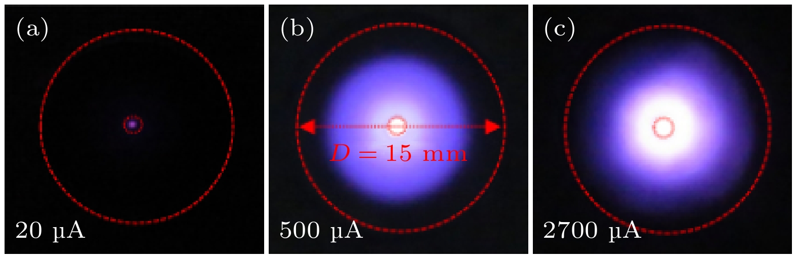
图 3 不同放电模式下放电图像(红线小圆: 微孔; 红线大圆: 电极片)
Fig. 3. The discharge images at different discharge modes (small red circle: cavity; large red circle: cathode electrode).
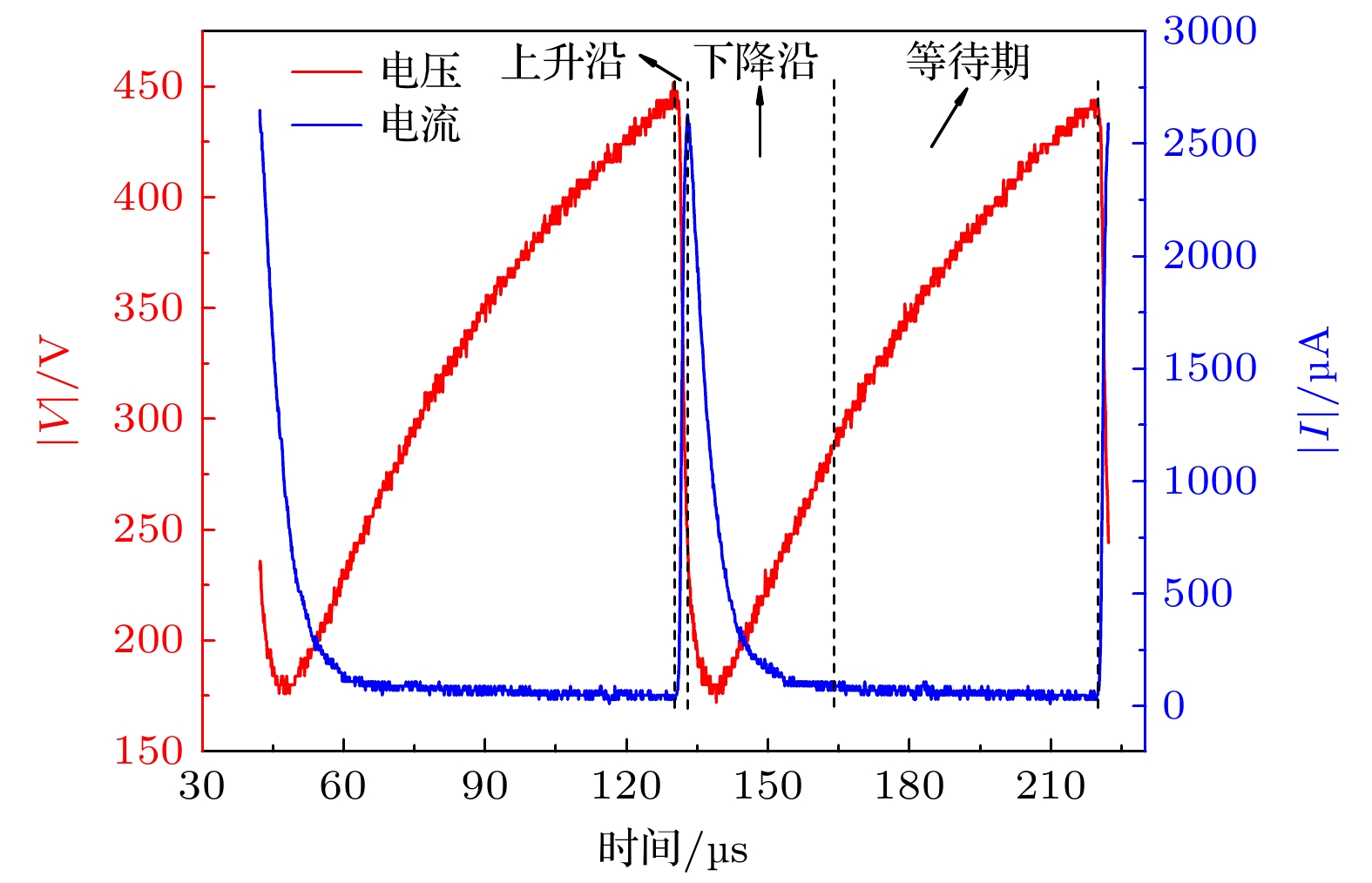
图 4 平均电流250 μA时的电压和电流脉冲波形图
Fig. 4. Voltage and current pulse waveforms at an average current of 250 μA.
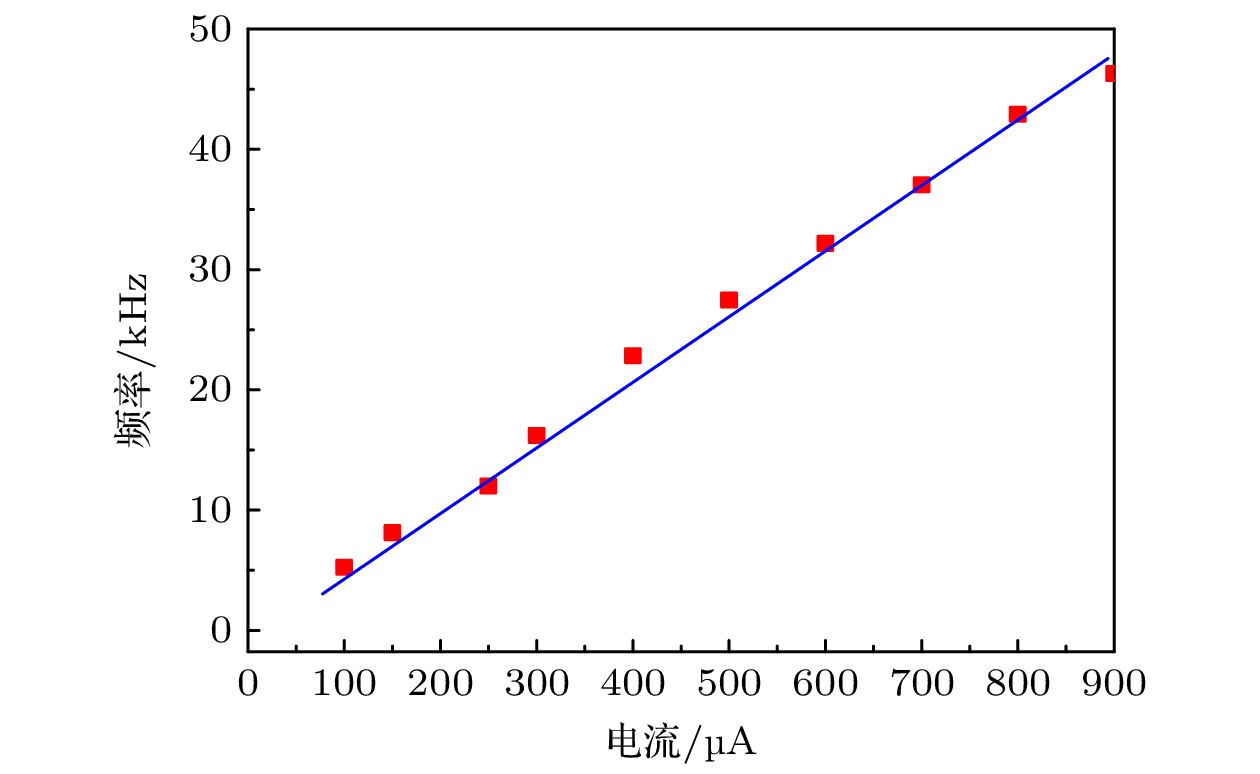
图 5 自脉冲频率随平均电流变化
Fig. 5. The self-pulsing frequency as a function of average discharge current.
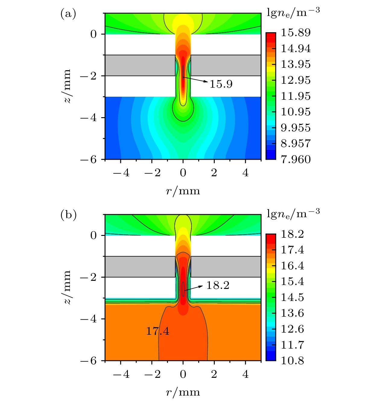
图 6 不同稳态放电模式下电子密度 (a)汤生放电模式I = 20 μA; (b)正常辉光放电模式I = 3000 μA
Fig. 6. Electron density at different stable discharge modes: (a) Townsend discharge at I = 20 μA; (b) normal glow discharge I = 3000 μA.
图 7 稳态放电模式下z = –2.5 mm处一维径向电场
Fig. 7. One dimensional radial electric field at z = –2.5 mm in stable discharge mode.
图 8 自脉冲放电电流模拟波形. tA = 58.9 μs, tB = 118.1 μs, tC = 131.3 μs, tD = 132.1 μs, tE = 146.3 μs
Fig. 8. The simulated discharge current waveform. tA = 58.9 μs, tB = 118.1 μs, tC = 131.3 μs, tD = 132.1 μs, tE = 146.3 μs.
图 9 不同时刻电势分布图 (a) 58.9 μs; (b) 118.1 μs; (c) 131.3 μs; (d) 132.1 μs; (e) 146.3 μs
Fig. 9. Electric potential at different time: (a)58.9 μs; (b) 118.1 μs; (c) 131.3 μs; (d) 132.1 μs; (e) 146.3 μs.
图 10 不同时刻电子密度分布图 (a) 58.9 μs; (b) 118.1 μs; (c) 131.3 μs; (d) 132.1 μs; (e) 146.3 μs
Fig. 10. Electron density distribution at different time: (a) 58.9 μs; (b) 118.1 μs; (c) 131.3 μs; (d) 132.1 μs; (e) 146.3 μs.
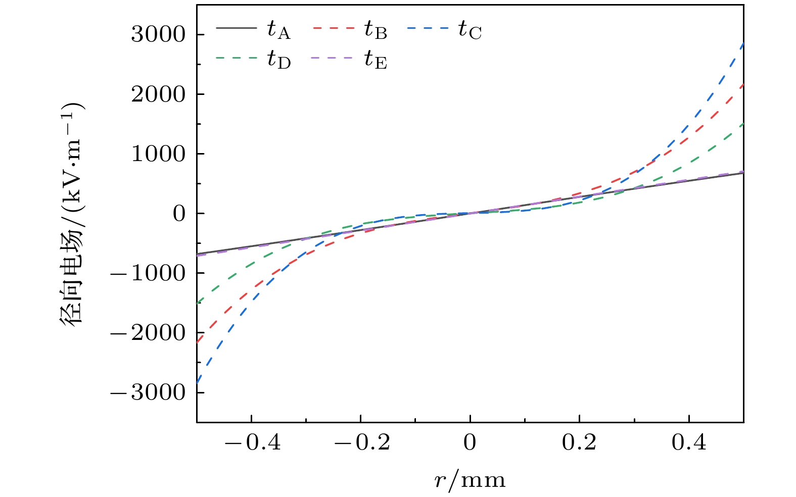
图 11 不同时刻z = –2.5 mm处径向电场分布图
Fig. 11. Radial electric field distribution at z = –2.5 mm at different time.
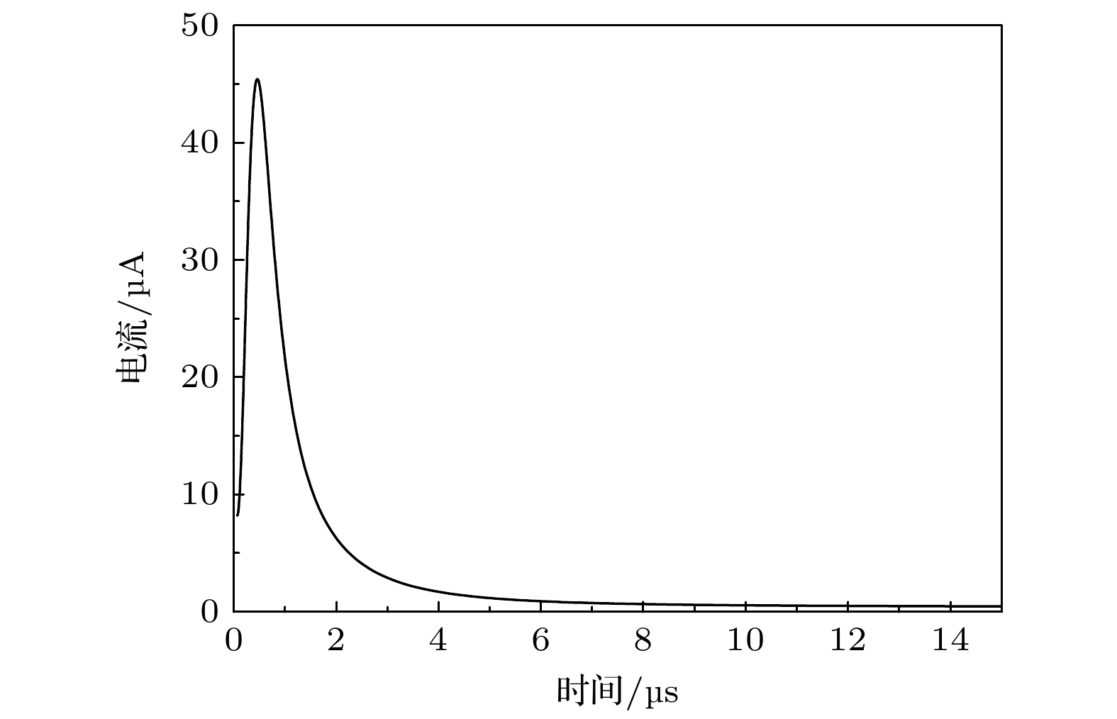
图 12 极间电压270 V时放电电流随时间变化图
Fig. 12. Discharge current evolution with time at a voltage of 270 V.
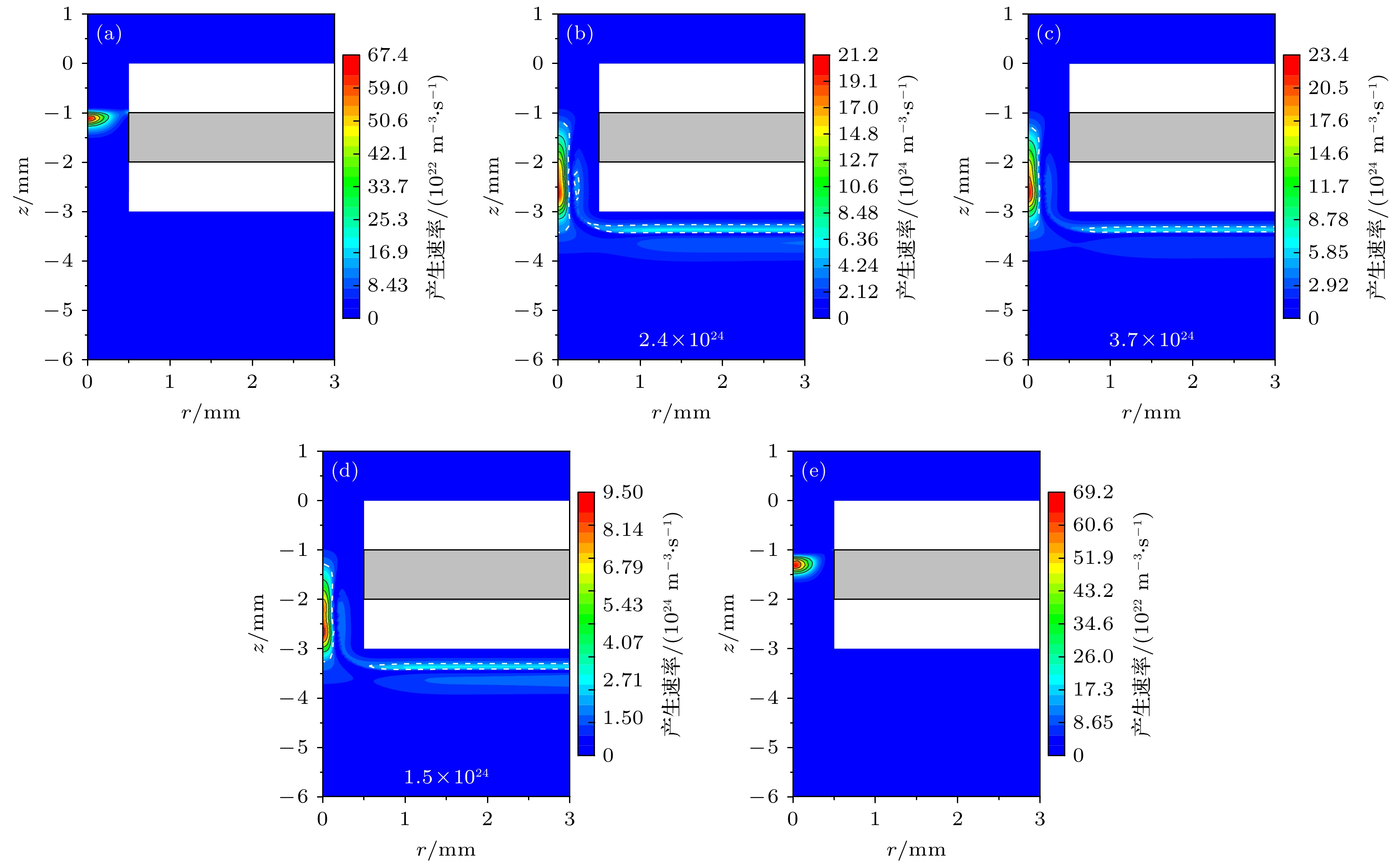
图 13 不同时刻电子产生速率分布图 (a) 58.9 μs; (b) 118.1 μs; (c) 131.3 μs; (d) 132.1 μs; (e) 146.3 μs
Fig. 13. Electron generation rate at different times: (a) 58.9 μs; (b) 118.1 μs; (c) 131.3 μs; (d) 132.1 μs; (e) 146.3 μs.
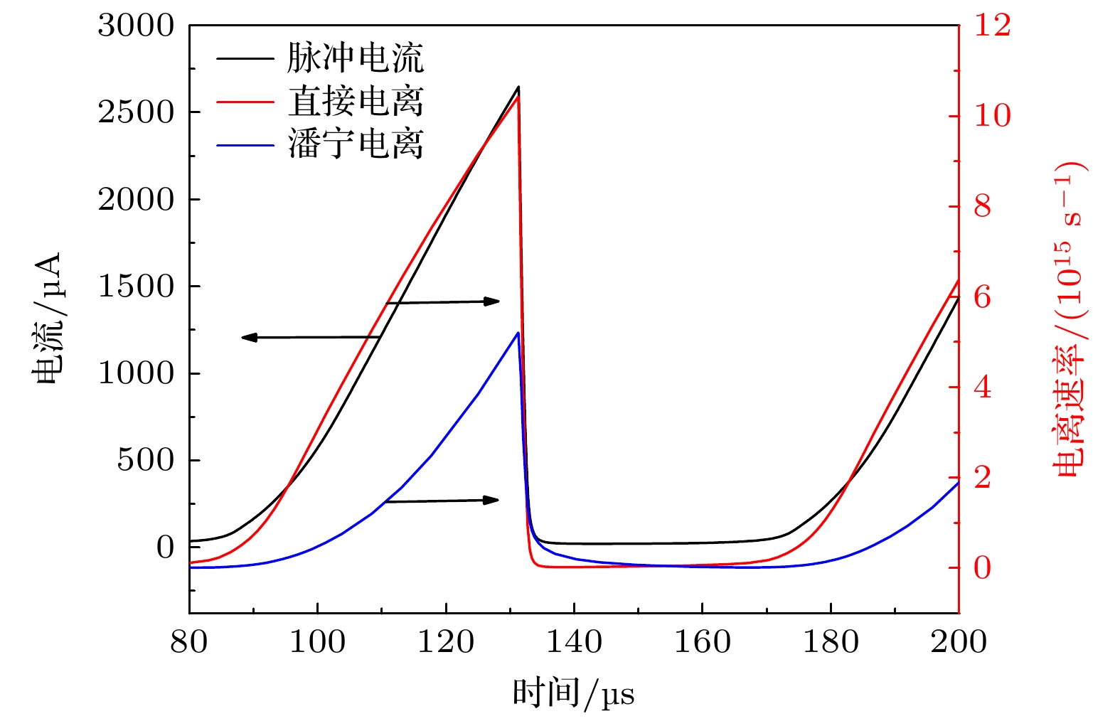
图 14 脉冲电流和不同电离速率时间演化图
Fig. 14. The evolution of pulse current and different ionization rates with time.
表 1 碰撞反应类型
Table 1. Collision reactions in the model.
反应类型 反应方程 直接电离 $\rm Ar+e = Ar^+ + 2e $ [16] 分步电离 $\rm Ar^*+e = Ar^+ + 2e $ [16] 基态激发 $\rm Ar + e = Ar^* + e $ [16] 弹性碰撞 $\rm Ar + e = Ar + e $ [16] 潘宁电离 $\rm Ar^*+Ar^* = Ar^+ + Ar + e $ [17] 两体碰撞 $\rm Ar^* +Ar = Ar+Ar $ [18] 三体碰撞 $\rm Ar^*+2Ar = Ar_2^*+Ar $ [19] 解激发 $\rm Ar^* + e = Ar + e + {\it hv} $ [19] 复合反应 $ \rm Ar^+ + e + e = Ar + e $ [20]  下载: 导出CSV
-
[1] 王震, 赵志航, 付洋洋 2024 73 125201
Google Scholar
Wang Z, Zhao Z H, Fu Y Y 2024 Acta Phys. Sin. 73 125201
Google Scholar
[2] Wei H C, Wang N, Duan Z C, He F 2018 Phys. Plasmas 25 123513
Google Scholar
[3] 邝勇, 章程, 胡修翠, 任晨华, 陈根永, 邵涛 2023 电工技术学报 38 3960
Kuang Y, Zhang C, Hu X C, Ren C H, Chen G Y, Shao T 2023 Trans. Chin. Electrotech. Soc. 38 3960
[4] 郭昱均, 季启政, 何锋, 廖劲松, 张宇, 欧阳吉庭 2019 高电压技术 45 820
Guo Y J, Ji Q Z, He F, Liao J S, Zhang Y, Ouyang J T 2019 High Voltage Eng. 45 820
[5] Saifutdinov A I, Sysoev S S 2023 Plasma Sources Sci. Technol. 32 114001
Google Scholar
[6] 赵立芬, 哈静, 王非凡, 李庆, 何寿杰 2022 71 025201
Google Scholar
Zhao L F, Ha J, Wang F F, Li Q, He S J 2022 Acta Phys. Sin. 71 025201
Google Scholar
[7] Schoenbach K H, Kurt B 2016 Eur. Phys. J. D 70 29
Google Scholar
[8] 欧阳吉庭, 张宇, 秦宇 2016 高电压技术 42 673684
Ouyang J T, Zhang Y, Qin Y 2016 High Voltage Eng. 42 673684
[9] Schoenbach K H, El-Habachi A, Shi W, Ciocca M 1997 Plasma Sources Sci. Technol. 6 468
Google Scholar
[10] Aubert X, Bauville G, Guillon J, Lacour B, Puech V, Rousseau A 2007 Plasma Sources Sci. Technol. 16 23
Google Scholar
[11] Qin Y, He F, Jiang X X, Xie K, Ouyang J T 2014 Phys. Plasmas 21 073501
Google Scholar
[12] Qin Y, Xie K, Zhang Y, Ouyang J T 2016 Phys. Plasmas 23 023501
Google Scholar
[13] Hsu D D, Graves D B 2003 J. Phys. D: Appl. Phys. 36 2898
Google Scholar
[14] Taylan O, Berberoglu H 2014 J. Appl. Phys. 116 043302
Google Scholar
[15] Lazzaroni C, Charbrert P 2011 Plasma Sources Sci. Technol. 20 2033
[16] Hagelaar G J M, Pitchford L C 2005 Plasma Sources Sci. Technol. 14 722
Google Scholar
[17] Ferreira C M, Loureiro L, Richard A 1985 J. Appl. Phys. 57 82
Google Scholar
[18] Karoulina E V, Lebedev Y A 1992 J. Phys. D: Appl. Phys. 25 401
Google Scholar
[19] Biondi M A 1963 Phys. Rev. 129 1181
Google Scholar
[20] Shon Jong W, Kushner M J 1994 J. Appl. Phys. 75 1883
Google Scholar
[21] He S J, Wang P, Ha J, Zhang B M, Zhang Z, Li Q 2018 Plasma Sci. Technol. 20 054006
Google Scholar
[22] Fu Y Y, Verboncoeur J P, Christlieb A J 2017 Phys. Plasmas 24 103514
Google Scholar
[23] Cui R L, He F, Miao J S, Ouyang J T 2017 Phys. Plasmas 24 103524
Google Scholar
[24] Chen S, Li K L, Nijdam S 2019 Plasma Sources Sci. Technol. 28 055017
Google Scholar
[25] 高嘉懋 2022 硕士学位论文 (武汉: 华中科技大学)
Gao J M. 2022 M. S. Thesis (Wuhan: Huazhong University of Science and Technology
[26] Levko D, Raja L 2021 J. Phys. D: Appl. Phys. 54 235201
Google Scholar
[27] Arslanbekov R R, Kolobov V I 2003 J. Phys. D: Appl. Phys. 36 2986
Google Scholar

 下载:
下载:


计量
- 文章访问数: 3302
- PDF下载量: 67
- 被引次数: 0
