


-
Ring resonator fabricated on a silicon-on-insulator is versatile in optical integration, which can be used to realize filters, modulators and switches. However, silicon-on-insulator is difficult to control the polarization dependence, and thus its application is greatly limited. The polarization dependence of the ring resonator is caused mainly by two factors: the coupling coefficients of the coupling region at the same wavelength for the two orthogonal polarization modes are different, and the birefringence effect of curved waveguide results in the different resonant wavelengths of TE and TM polarization modes. When the coupling region polarization independence and the resonant wavelength polarization independence are simultaneously satisfied, the polarization independence of the ring resonator can be realized. In this paper, a new type of polarization-insensitive ring resonator on a silicon-on-insulator is designed based on subwavelength grating and sandwiched structure. Firstly, by adjusting the duty cycle of the subwavelength grating and the refractive index of SiNx in the coupling region, polarization independence of the coupling region is achieved. Secondly, the refractive index of SiNx in curved waveguides is designed to make the resonance wavelengths for orthogonal polarization modes equal. Thirdly, the parameters of the coupling region are optimized to reduce the insertion loss. The three-dimensional finite-difference time-domain method is used for simulation. The results show that the radius of the ring is only 10 μm, the 3-dB bandwidth of the device is less than 0.8 nm, and the insertion loss is lower than 0.8 dB. It has potential applications in the future dense wavelength division multiplexing systems.
-
Keywords:
- microring resonators /
- polarization-insensitive /
- subwavelength grating /
- sandwiched structure
[1] Lee J M, Park S, Kim G 2008 Opt. Commun. 281 4302
 Google Scholar
[2] Sang-Ngern S, Roeksabutr A 2006 IEEE Asia Pacific Conference on Circuits and Systems Singapore, December 4–7, 2006 p1907
[3] Heyn P D, Coster J D, Verheyem P, Lepage G, Pantouvaki M, Absil P, Bogaerts W, Campenhout J V, Thourhout D V 2013 J. Lightwave Technol. 31 2785
Google Scholar
[4] Chao I F, Lee C H, Chung Y H 2019 4th International Conference on Intelligent Green Building and Smart Grid (IGBSG) Yichang, China, September 6–9, 2019 p30
[5] Kudo M, Ohta S, Taguchi E, Fujisawa T, Sakamoto T, Matsui T, Tsujikawa K, Nakajima K, Saitoh K 2019 Opt. Commun. 433 168
Google Scholar
[6] Balaji V R, Murugan M, Robinson S 2016 International Conference on Wireless Communications, Signal Processing and Networking (WiSPNET) Chennai, India, March 23–25, 2016 p33
[7] Libertino S, Coffa S, Saggio M 2000 Mater. Sci. Semicond. Process. 3 375
Google Scholar
[8] Vlasov Y, Mcnab S 2004 Opt. Express 12 1622
Google Scholar
[9] Xu Q F, Fattal D, Beausoleil R G 2008 Opt. Express 16 4309
Google Scholar
[10] Barwicz T, Watts M R, Popovi M A, Rakich P T, Socci L, Krtner F X, Ippen E P, Smith H I 2007 Nat. Photonics 1 57
Google Scholar
[11] Xu D X, Janz S, Cheben P 2006 IEEE Photonics Technol. Lett. 18 343
Google Scholar
[12] Geng M M 2016 Laser Optoelectron. Prog. 53 182
Google Scholar
[13] Wang X D, Li Y Q, Quan X L, Cheng X L 2019 Conference on Lasers and Electro-Optics (CLEO) Munich, Germany, June 23–27, 2019 JTh2 A.64
[14] Chen Y, Joines W T 2003 Opt. Commun. 228 319
Google Scholar
[15] Kaalund C J 2004 Opt. Commun. 237 357
Google Scholar
[16] Little B E, Chu S T, Haus H A, Foresi J, Laine J P 1997 J. Lightwave Technol. 15 998
Google Scholar
[17] Lee C C, Chen H L, Hsu J C, Tien C L 1999 Appl. Opt. 38 2078
Google Scholar
[18] 邹祥云, 苑进社, 蒋一祥 2012 61 148106
Google Scholar
Zou X Y, Yuan J S, Jiang Y X 2012 Acta Phys. Sin. 61 148106
Google Scholar
[19] 汪静丽, 陈子玉, 陈鹤鸣 2020 69 054206
Google Scholar
Wang J L, Chen Z Y, Chen H M 2020 Acta Phys. Sin. 69 054206
Google Scholar
[20] Shi Y J, Shang H P, Sun D G 2018 Opt. Commun. 410 211
Google Scholar
[21] 张福领, 翟珊, 潘俊, 冯吉军 2020 中国激光 43 1
Google Scholar
Zhang F L, Zhai S, Pan J, Feng J J 2020 Chin. J. Lasers 43 1
Google Scholar
[22] 柳襄怀, 薛滨, 郑志宏, 周祖尧, 邹世昌 1989 半导体学报 1989 457
Google Scholar
Liu X H, Xue B, Zheng Z H, Zhou Z Y, Zhou S Z 1989 J. Semicond. 1989 457
Google Scholar
-

图 1 基于SWG和三明治结构的偏振无关微环谐振器结构示意图 (a) 俯视图; (b) 波导横截面示意图; (c) 基于SWG和三明治结构的耦合区三维结构示意图; (d) 耦合区Si层俯视图; (e) 耦合区SiNx层俯视图
Figure 1. Schematic configuration of the polarization insensitive ring resonator based on SWG and sandwiched structure: (a) Top view; (b) cross section of the waveguide; (c) three-dimensional schematic configuration of the polarization insensitive coupling region based on subwavelength grating slot waveguides and sandwiched structure; (d) top view of Si layer in coupling region; (e) top view of SiNx layer in coupling region.

图 2 耦合区中的光场分布图 (a) TE偏振模; (b) TM偏振模
Figure 2. Field distributions in the coupling region: (a) TE polarization mode; (b) TM polarization mode.
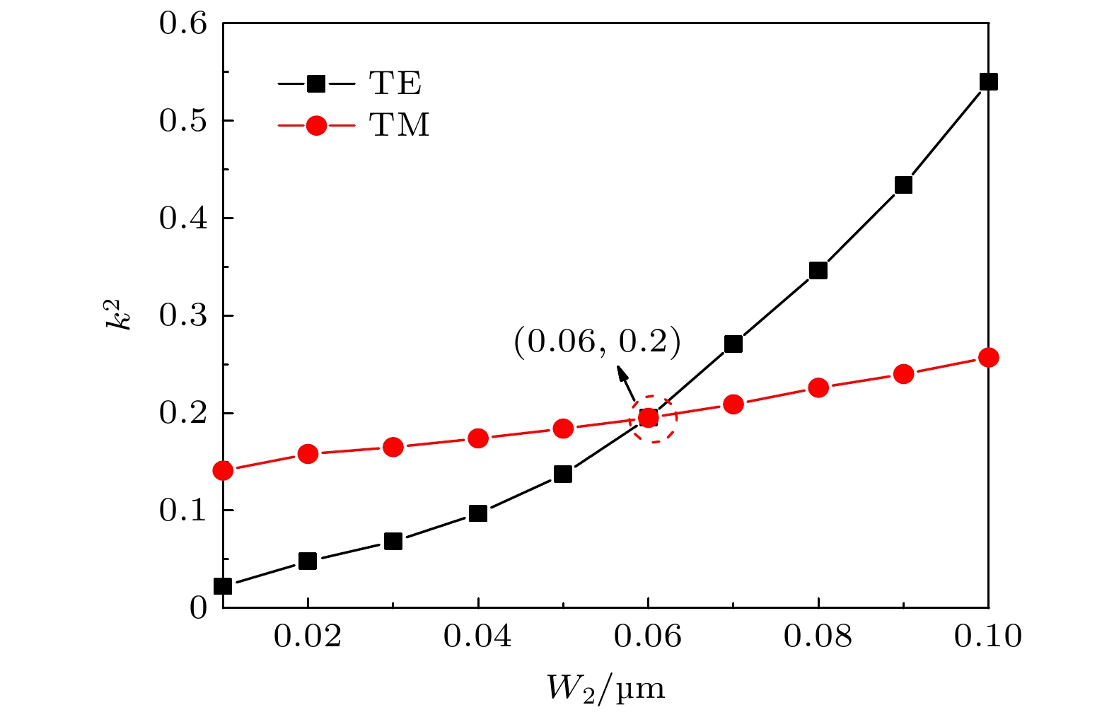
图 3 k 2随W2的变化
Figure 3. k 2 as a function of W2.

图 4 (a) 耦合区满足偏振无关时, 不同n1(SiNx)情况下k 2随g的变化; (b) 每一组g和n1(SiNx)实现耦合区偏振无关时其对应的W2
Figure 4. (a) k 2 as a function of g under different n1(SiNx) when the light intensity is polarization-insensitive; (b) W2 as a function of g under different n1(SiNx) when the light intensity is polarization-insensitive

图 5 Δλ随n 2 (SiNx)的变化
Figure 5. Δλ as a function of n 2 (SiNx) in ring.

图 6 k 2随g的变化
Figure 6. k 2 of download port as a function of g.
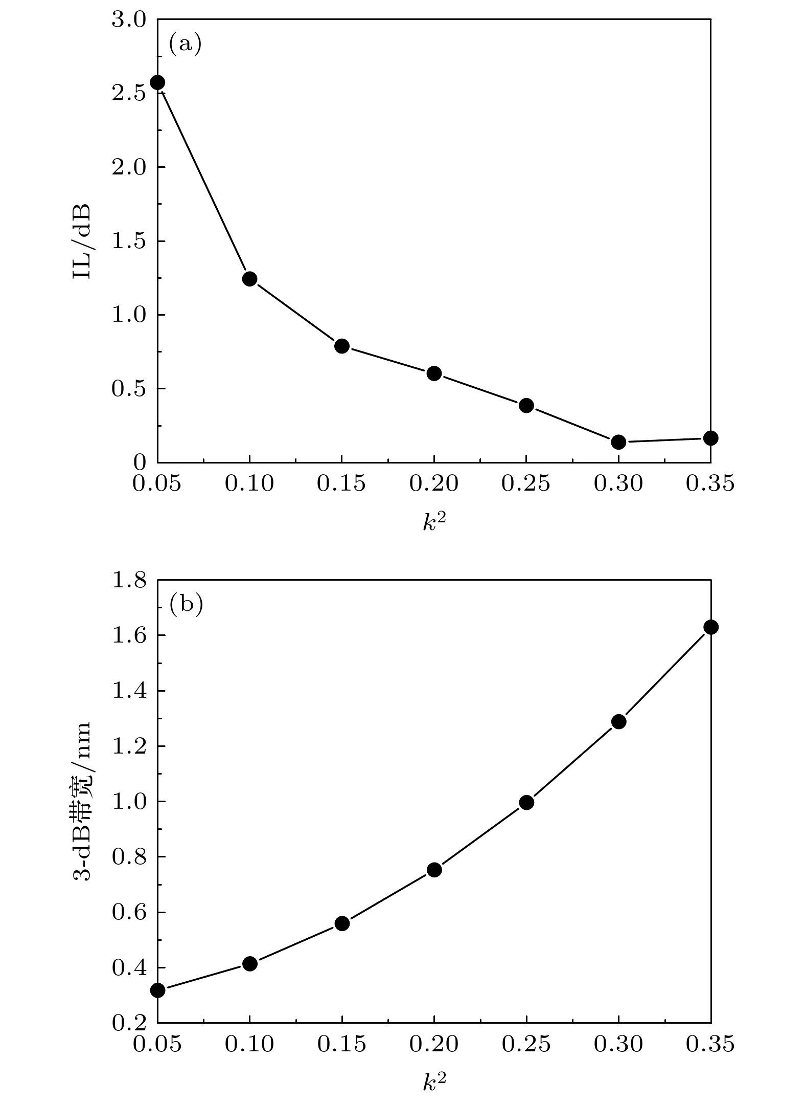
图 7 (a) k 2变化对IL的影响; (b) k 2变化对3-dB带宽的影响
Figure 7. (a) IL of download port as a function of k 2; (b) 3-dB bandwidth as a function of k 2.

图 8 微环谐振器偏振无关且k 2 = 0.2时n1 (SiNx)变化对IL的影响
Figure 8. IL as a function of n1(SiNx) when the ring resonator is polarization-insensitive and k 2 = 0.2.
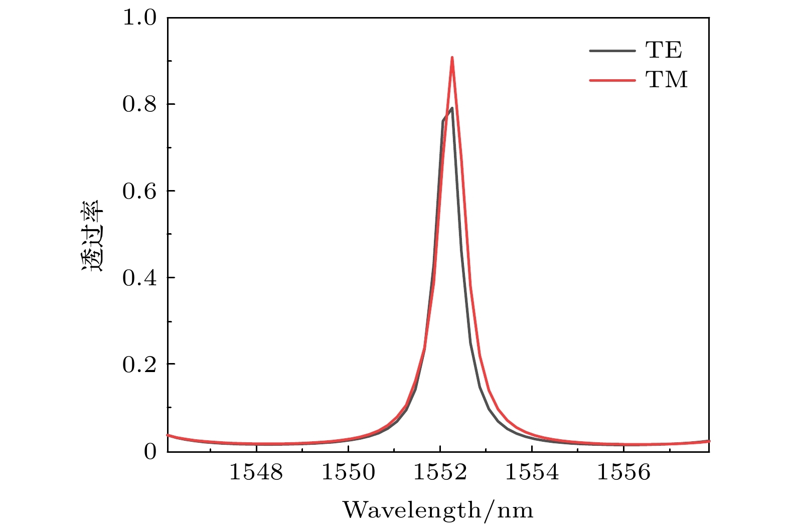
图 9 TE和TM偏振模时的输出端透过率谱线
Figure 9. Measured transmission spectra with TE- and TM-polarized light inputs for the out port.
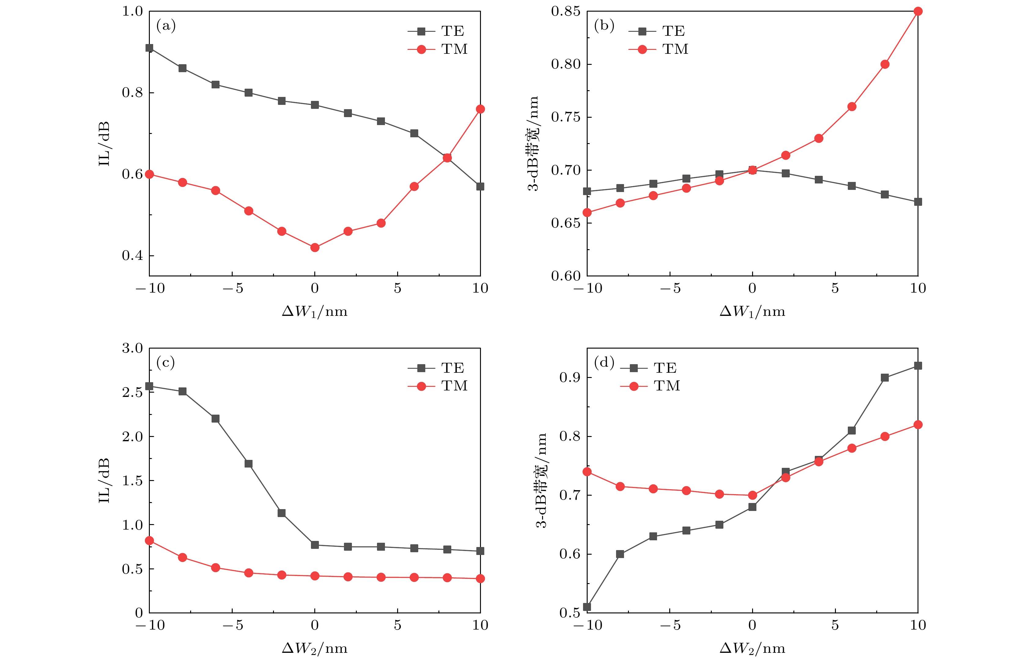
图 10 器件性能随结构参数的变化 (a) IL随ΔW1的变化; (b) 3-dB带宽随ΔW1的变化; (c) IL随ΔW2的变化; (d) 3-dB带宽随ΔW2的变化
Figure 10. Performances as functions of structural parameters: (a) IL as a function of ΔW1; (b) 3-dB bandwidth as a function of ΔW1; (c) IL as a function of ΔW2; (d) 3-dB bandwidth as a function of ΔW2.
表 1 偏振无关微环谐振器的性能参数
Table 1. Performances of the polarization-insensitive ring resonator.
 DownLoad: CSV
-
[1] Lee J M, Park S, Kim G 2008 Opt. Commun. 281 4302
Google Scholar
[2] Sang-Ngern S, Roeksabutr A 2006 IEEE Asia Pacific Conference on Circuits and Systems Singapore, December 4–7, 2006 p1907
[3] Heyn P D, Coster J D, Verheyem P, Lepage G, Pantouvaki M, Absil P, Bogaerts W, Campenhout J V, Thourhout D V 2013 J. Lightwave Technol. 31 2785
Google Scholar
[4] Chao I F, Lee C H, Chung Y H 2019 4th International Conference on Intelligent Green Building and Smart Grid (IGBSG) Yichang, China, September 6–9, 2019 p30
[5] Kudo M, Ohta S, Taguchi E, Fujisawa T, Sakamoto T, Matsui T, Tsujikawa K, Nakajima K, Saitoh K 2019 Opt. Commun. 433 168
Google Scholar
[6] Balaji V R, Murugan M, Robinson S 2016 International Conference on Wireless Communications, Signal Processing and Networking (WiSPNET) Chennai, India, March 23–25, 2016 p33
[7] Libertino S, Coffa S, Saggio M 2000 Mater. Sci. Semicond. Process. 3 375
Google Scholar
[8] Vlasov Y, Mcnab S 2004 Opt. Express 12 1622
Google Scholar
[9] Xu Q F, Fattal D, Beausoleil R G 2008 Opt. Express 16 4309
Google Scholar
[10] Barwicz T, Watts M R, Popovi M A, Rakich P T, Socci L, Krtner F X, Ippen E P, Smith H I 2007 Nat. Photonics 1 57
Google Scholar
[11] Xu D X, Janz S, Cheben P 2006 IEEE Photonics Technol. Lett. 18 343
Google Scholar
[12] Geng M M 2016 Laser Optoelectron. Prog. 53 182
Google Scholar
[13] Wang X D, Li Y Q, Quan X L, Cheng X L 2019 Conference on Lasers and Electro-Optics (CLEO) Munich, Germany, June 23–27, 2019 JTh2 A.64
[14] Chen Y, Joines W T 2003 Opt. Commun. 228 319
Google Scholar
[15] Kaalund C J 2004 Opt. Commun. 237 357
Google Scholar
[16] Little B E, Chu S T, Haus H A, Foresi J, Laine J P 1997 J. Lightwave Technol. 15 998
Google Scholar
[17] Lee C C, Chen H L, Hsu J C, Tien C L 1999 Appl. Opt. 38 2078
Google Scholar
[18] 邹祥云, 苑进社, 蒋一祥 2012 61 148106
Google Scholar
Zou X Y, Yuan J S, Jiang Y X 2012 Acta Phys. Sin. 61 148106
Google Scholar
[19] 汪静丽, 陈子玉, 陈鹤鸣 2020 69 054206
Google Scholar
Wang J L, Chen Z Y, Chen H M 2020 Acta Phys. Sin. 69 054206
Google Scholar
[20] Shi Y J, Shang H P, Sun D G 2018 Opt. Commun. 410 211
Google Scholar
[21] 张福领, 翟珊, 潘俊, 冯吉军 2020 中国激光 43 1
Google Scholar
Zhang F L, Zhai S, Pan J, Feng J J 2020 Chin. J. Lasers 43 1
Google Scholar
[22] 柳襄怀, 薛滨, 郑志宏, 周祖尧, 邹世昌 1989 半导体学报 1989 457
Google Scholar
Liu X H, Xue B, Zheng Z H, Zhou Z Y, Zhou S Z 1989 J. Semicond. 1989 457
Google Scholar


 DownLoad:


Catalog
Metrics
- Abstract views: 8185
- PDF Downloads: 103
- Cited By: 0
