


-
基于流体模型探讨了大气压空气中快纳秒脉冲上升沿引发的弥散放电对等离子体计算域边界与泊松方程计算域边界范围的敏感性和影响机制. 通过对比不同边界范围的仿真结果与实验数据, 尤其是位于整个矩形计算域的最上方边界(上边界)和最右侧边界(右边界): 1)当等离子体边界与泊松方程边界均采用比放电本身半径宽6倍以上的边界范围时, 放电宽度与传播速度与实验吻合度较高, 但放电到达板电极时刻仍存在流体模型所具有的普遍性延迟; 2)等离子体计算域边界的缩减仅使放电头部电场强度与电子密度产生可忽略的微弱波动, 证明其对弥散放电宏观特性影响甚微; 3)泊松方程计算域右边界范围缩减导致放电宽度显著降低, 其放电宽度-计算域比值递增, 且放电在上、下半间隙呈现非对称传播特征, 但适当缩减右边界可改善放电形貌与实验的匹配度; 4)泊松方程计算域上边界缩减会弱化放电头部电场“聚焦效应”, 导致空间电场分布均匀化, 延缓放电加速过程, 使仿真结果偏离实验更显著. 泊松方程边界范围对放电时空演化具有决定性影响, 其中计算域上边界缩减会严重损害仿真精度, 而右边界调整可权衡计算效率与结果可靠性.Diffuse discharges generated by fast rising edge of nanosecond pulses possess a larger discharge radius than classic streamer discharges. However, existing simulation studies often employ boundary ranges similar to those used for simulating streamer discharges, thus neglecting the influence of the boundary range on their characteristics. In this work, the characteristics of diffuse discharges in atmospheric-pressure air are investigated using a fluid model. The research focuses on the influences of plasma and Poisson equation boundary ranges, especially the top and right boundaries of the rectangular computational domain, on discharge evolution. The comparison between numerical simulations and experimental results reveals several key findings: When both plasma and Poisson equation boundaries are set to 5 cm×5 cm (exceeding six times the maximum discharge radius), the simulated discharge width and propagation velocity accord well with experimental measurements. However, consistent delays are observed in simulating the time required to reach the plate electrode, highlighting the inherent limitations of current fluid models in accurately simulating temporal scales. Reducing the plasma boundaries results in negligible fluctuations in electric field strength and electron density at the discharge head, indicating a minimal effect on macroscopic discharge characteristics. Narrowing the Poisson equation’s right boundary significantly reduces the discharge width while simultaneously increasing the discharge width relative to the domain size. Asymmetric propagation patterns occur between the upper and lower halves of the discharge gap. Nevertheless, appropriate reduction of the right boundary improves morphological consistency with experimental observations, thereby suggesting practical optimization strategies. Conversely, reducing the top boundary weakens the electric field “focusing effect” at the discharge head, homogenizes the spatial field distribution, and delays accelerating, thereby exacerbating deviations from experimental data. These results demonstrate that Poisson boundary conditions critically govern spatiotemporal discharge dynamics. Top boundary truncation significantly reduces the simulation accuracy, whereas adjusting the right boundary allows for a balanced optimization between computational efficiency and result reliability. This work provides theoretical guidance for selecting boundary conditions in the numerical modeling of diffuse discharges.
-
Keywords:
- nanosecond pulsed diffuse discharge /
- fluid model /
- streamer discharge /
- boundary conditions
[1] Chng T L, Pai D Z, Guaitella O, Starikovskaia S M, Bourdon A 2022 Plasma Sources Sci. Techn. 31 015010
 Google Scholar
[2] Brisset A, Guenin T, Tardiveau P, Sobota A 2023 Plasma Sources Sci. Techn. 32 065014
Google Scholar
[3] Babaeva N Y, Naidis G V 2016 Phys. Plasmas 23 083527
Google Scholar
[4] Nijdam S, Teunissen J, Ebert U 2020 Plasma Sources Sci. Techn. 29 103001
Google Scholar
[5] Marode E, Dessante P, Tardiveau P 2016 Plasma Sources Sci. Techn. 25 064004
Google Scholar
[6] Tardiveau P, Moreau N, Bentaleb S, Postel C, Pasquiers S 2009 J. Phys. D Appl. Phys. 42 175202
Google Scholar
[7] Babaeva N Y, Naidis G V, Tereshonok D V, Son E E 2018 J. Phys. D Appl. Phys. 51 434002
Google Scholar
[8] Bourdon A, Péchereau F, Tholin F, Bonaventura Z 2021 J. Phys. D Appl. Phys. 54 075204
Google Scholar
[9] Bourdon A, Péchereau F, Tholin F, Bonaventura Z 2021 Plasma Sources Sci. Techn. 30 105022
Google Scholar
[10] Zhu Y F, Chen X C, Wu Y, Hao J B, Ma X G, Lu P F, Tardiveau P 2021 Plasma Sources Sci. Techn. 30 075025
Google Scholar
[11] Brisset A, Gazeli K, Magne L, Pasquiers S, Jeanney P, Marode E, Tardiveau P 2019 Plasma Sources Sci. Techn. 28 055016
Google Scholar
[12] Guo Y L, Li Y R, Zhu Y F, Sun A B 2023 Plasma Sources Scie. Techn. 32 025003
Google Scholar
[13] Grubert G K, Becker M M, Loffhagen D 2009 Phys. Rev. E 80 036405
Google Scholar
[14] Bourdon A, Pasko V P, Liu N Y, Célestin S, Ségur P, Marode E 2007 Plasma Sources Sci. Techn. 16 656
Google Scholar
[15] Pancheshnyi S 2015 Plasma Sources Sci. Techn. 24 015023
Google Scholar
[16] Phelps A V, Pitchford L C 1985 Phys. Rev. A 31 2932
Google Scholar
[17] Lawton S A, Phelps A V 1978 J. Chem. Phys. 69 1055
Google Scholar
[18] Pancheshnyi S 2013 J. Phys. D Appl. Phys. 46 155201
Google Scholar
[19] Kossyi I A, Kostinsky A Y, Matveyev A A, Silakov V P 1992 Plasma Sources Sci. Techn. 1 207
Google Scholar
[20] Pancheshnyi S, Nudnova M, Starikovskii A 2005 Phys. Rev. E 71 016407
Google Scholar
[21] Li X R, Dijcks S, Nijdam S, Sun A B, Ebert U, Teunissen J 2021 Plasma Sources Sci. Techn. 30 095002
Google Scholar
[22] Li X R, Guo B H, Sun A B, Ebert U, Teunissen J 2022 Plasma Sources Science & Technology 31 065011
Google Scholar
[23] Guo B H, Li X R, Ebert U, Teunissen J 2022 Plasma Sources Sci. Techn. 31 095011
Google Scholar
[24] 李晗蔚, 孙安邦, 张幸, 姚聪伟, 常正实, 张冠军 2018 67 045101
Google Scholar
Li H W, Sun A B, Zhang X, Yao C W, Chang Z S, Zhang G J 2018 Acta Phys. Sin. 67 045101
Google Scholar
[25] Li Y T, Fu Y Y, Liu Z G, Li H D, Wang P, Luo H Y, Zou X B, Wang X X 2022 Plasma Sources Sci. Techn. 31 045027
Google Scholar
[26] 章程, 马浩, 邵涛, 谢庆, 杨文晋, 严萍 2014 63 085208
Google Scholar
Zhang C, Ma H, Shao T, Xie Q, Yang W J, Yan P 2014 Acta Phys. Sin. 63 085208
Google Scholar
[27] Shao T, Tarasenko V F, Yang W J, Beloplotov D V, Zhang C, Lomaev M I, Yan P, Sorokin D A 2014 Chin. Phys. Lett. 31 085201
Google Scholar
-
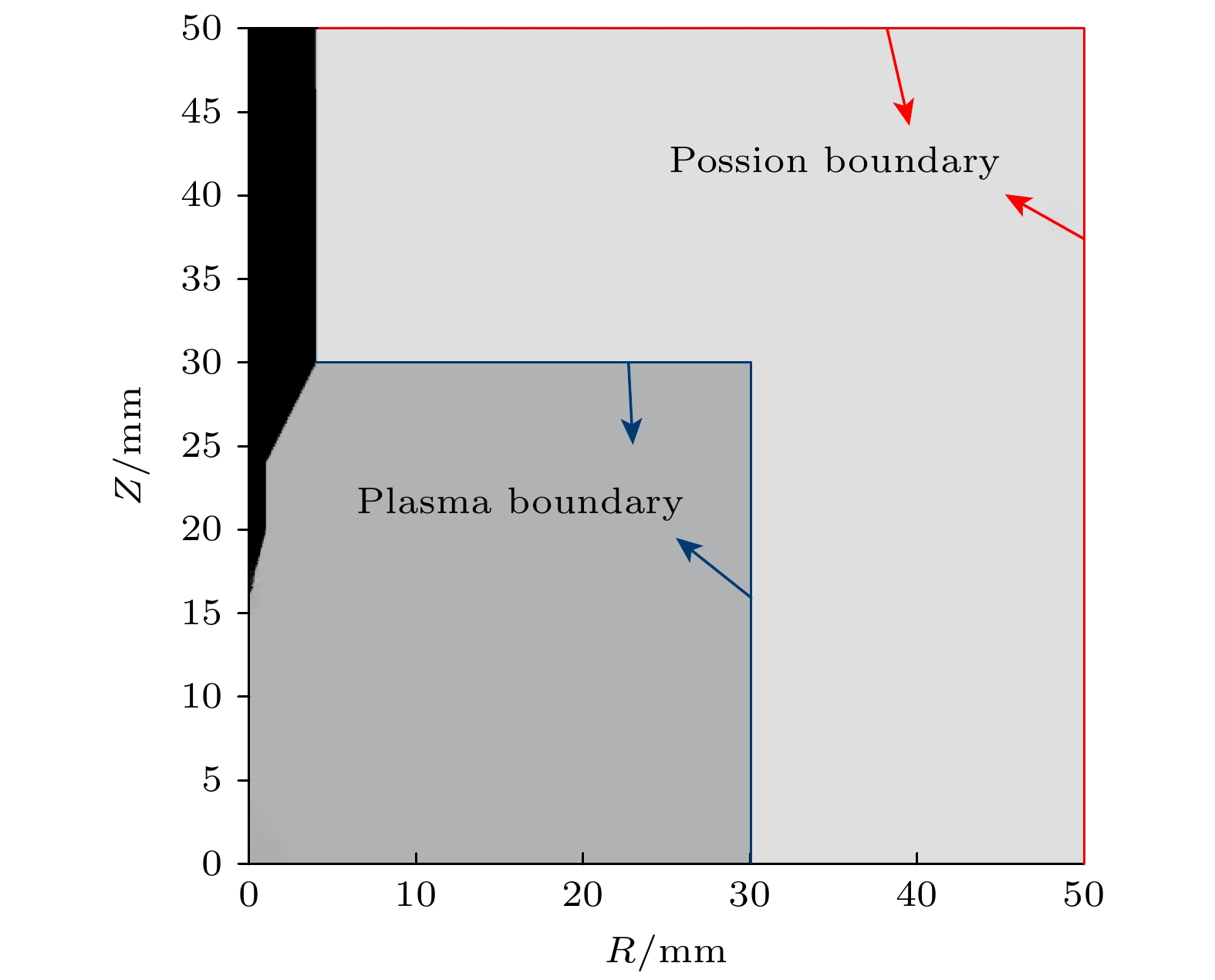
图 1 仿真中采用的电极结构和计算域示意图, 图中边界范围大小的数值仅作为结构示意, 在下文中针对其进行修改以研究仿真结果变化规律
Fig. 1. Schematic diagram of the electrode structure and computational domain used in the simulation, the numerical values for the boundary extent shown in the figure are purely for schematic illustration. These values will be systematically modified in the subsequent sections to investigate the trends in simulation results.
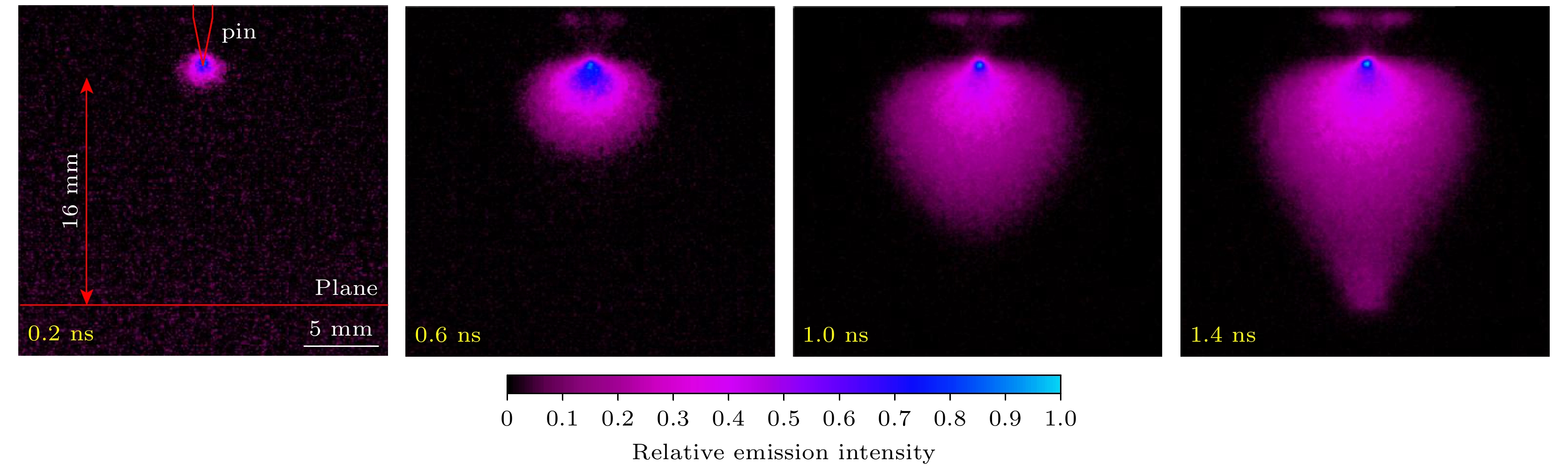
图 3 ICCD拍摄到的放电发展过程, 拍摄门宽为200 ps
Fig. 3. Discharge development captured by ICCD, gate used is 200 ps.
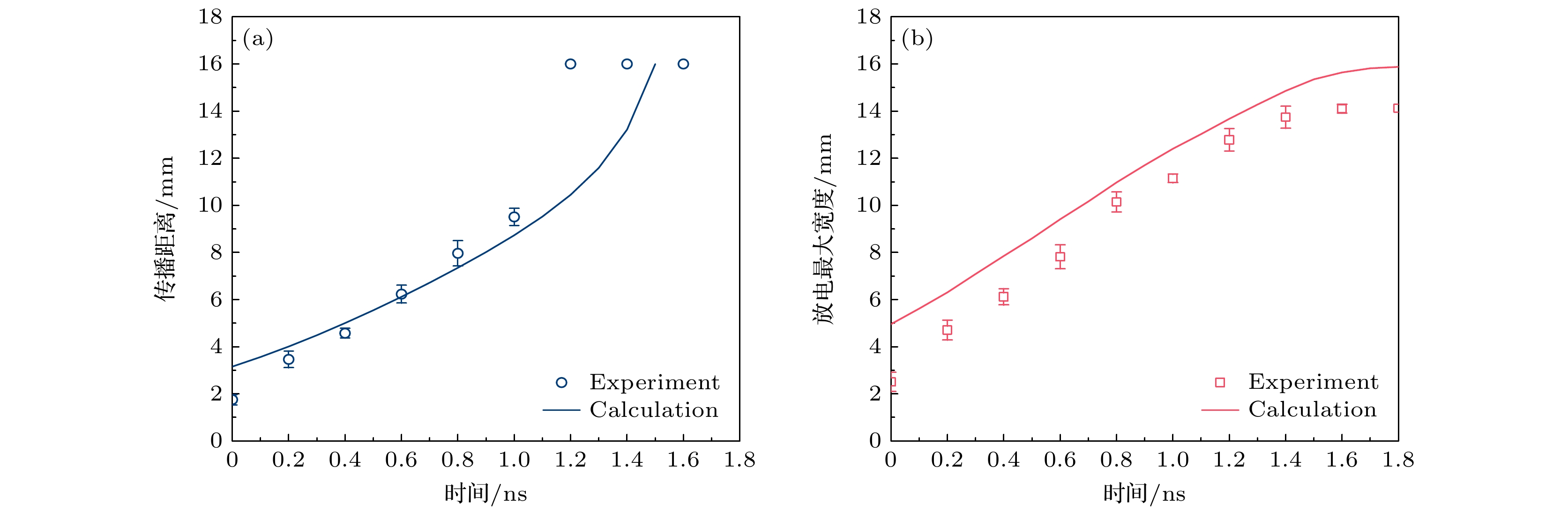
图 5 放电发展过程中传播距离和宽度的实验和仿真值对比 (a)放电传播距离; (b)放电最大宽度
Fig. 5. Simulated and experimental discharge length and width comparison: (a) Discharge length; (b) discharge width.
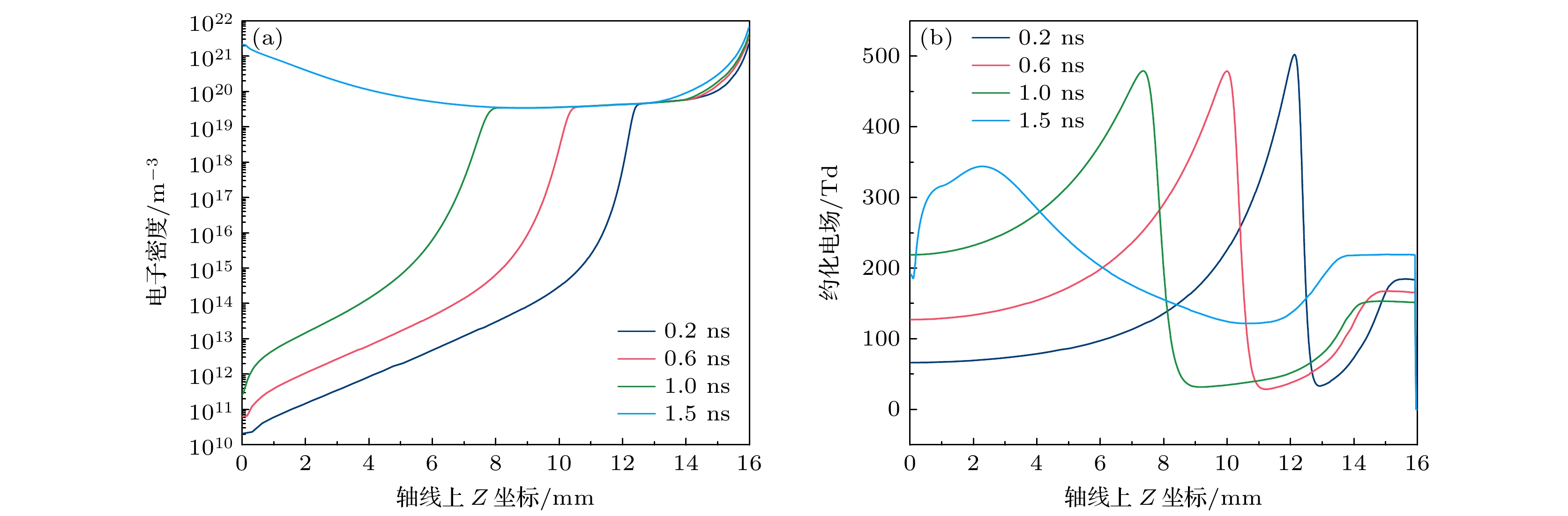
图 6 放电发展过程中电子密度和约化电场强度(单位: Td)在轴线上的分布 (a)电子密度; (b)约化电场强度
Fig. 6. Electron density and reduced electric field (in Td) distribution on the axis during the discharge development: (a) Electron density; (b) reduced electric field.
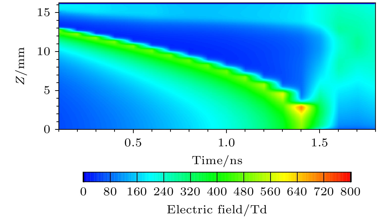
图 7 放电发展过程中约化电场强度(单位: Td)在轴线上的演化
Fig. 7. Reduced electric field (in Td) evolution on the axis during the discharge development.
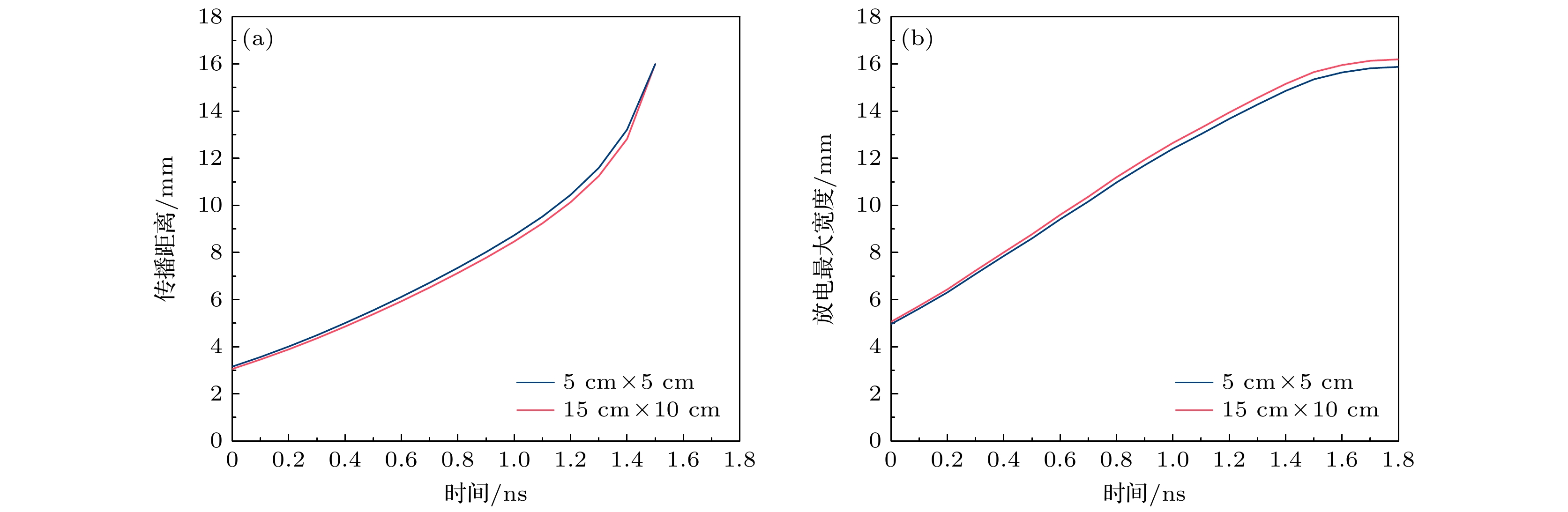
图 8 两种不同计算策略下放电发展过程中传播距离和宽度的实验和仿真值对比 (a)放电传播距离; (b)放电最大宽度
Fig. 8. Simulated and experimental discharge length and width comparison in two different calculation strategies: (a) Discharge length; (b) discharge width.
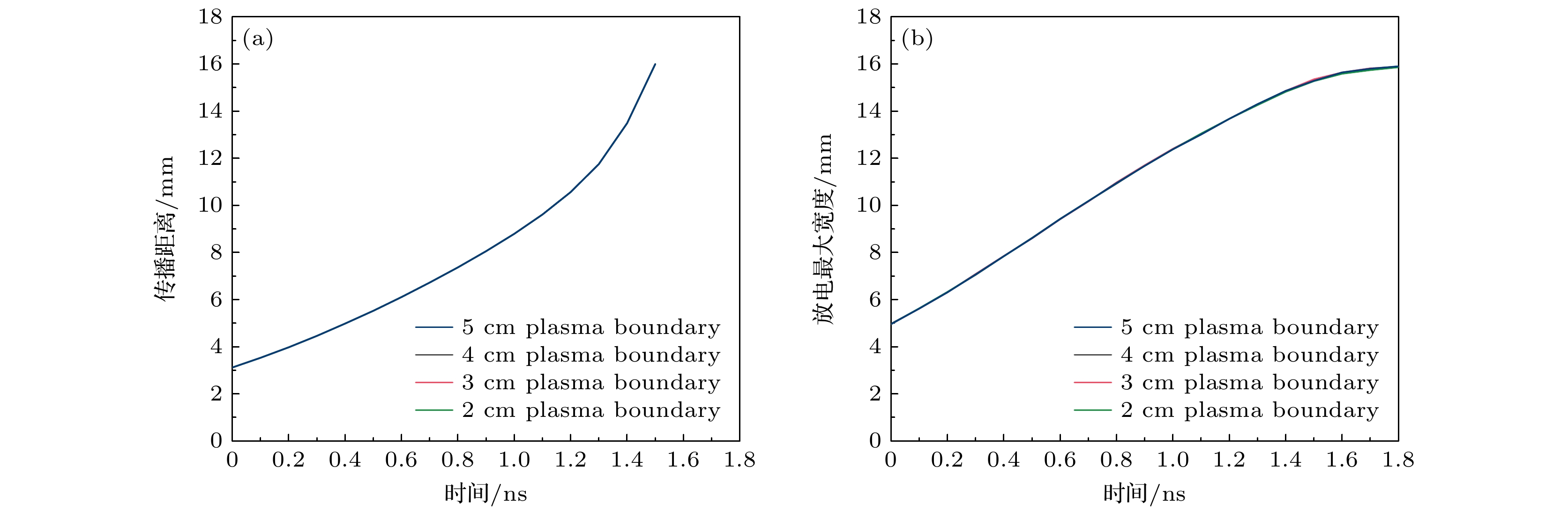
图 9 不同等离子体边界范围条件影响下放电传播距离和宽度变化规律 (a)放电传播距离; (b) 放电最大宽度
Fig. 9. Discharge length and width influenced by different plasma boundaries: (a) Discharge length; (b) discharge width.
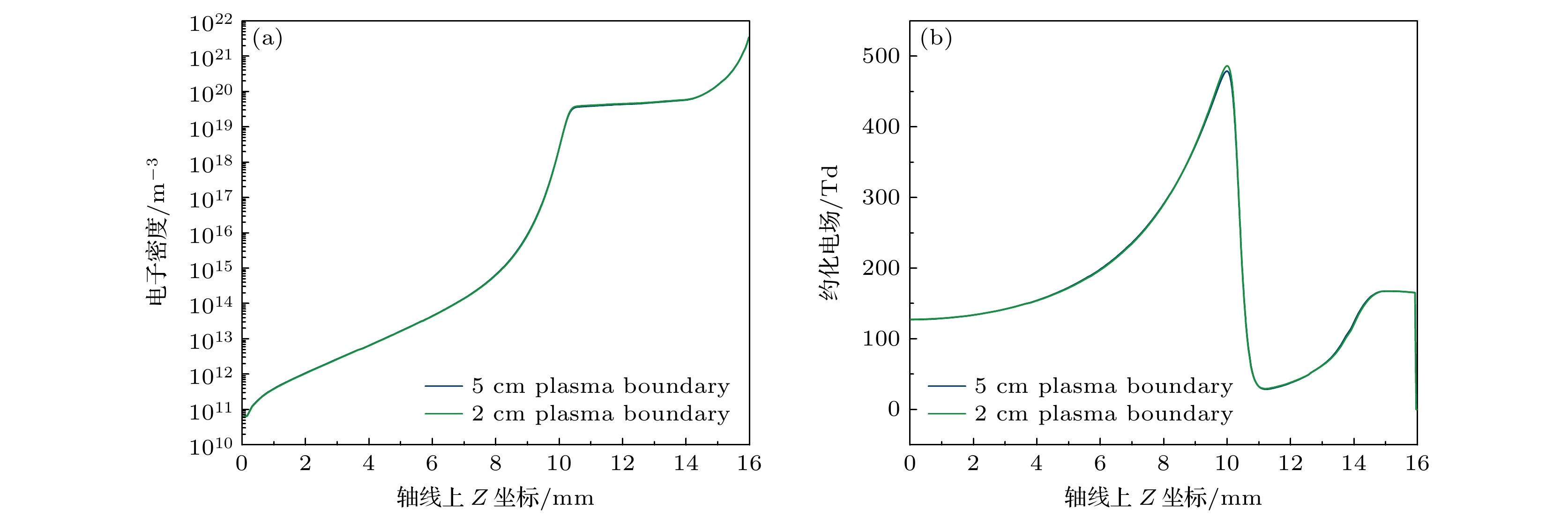
图 10 不同等离子体边界范围条件影响下t = 0.6 ns时刻下电子密度和电场强度在轴线上的分布 (a)电子密度; (b)约化电场强度
Fig. 10. Electron density distribution on the axis at t = 0.6 ns under the influence of different plasma boundaries: (a) Electron density; (b) reduced electric field.
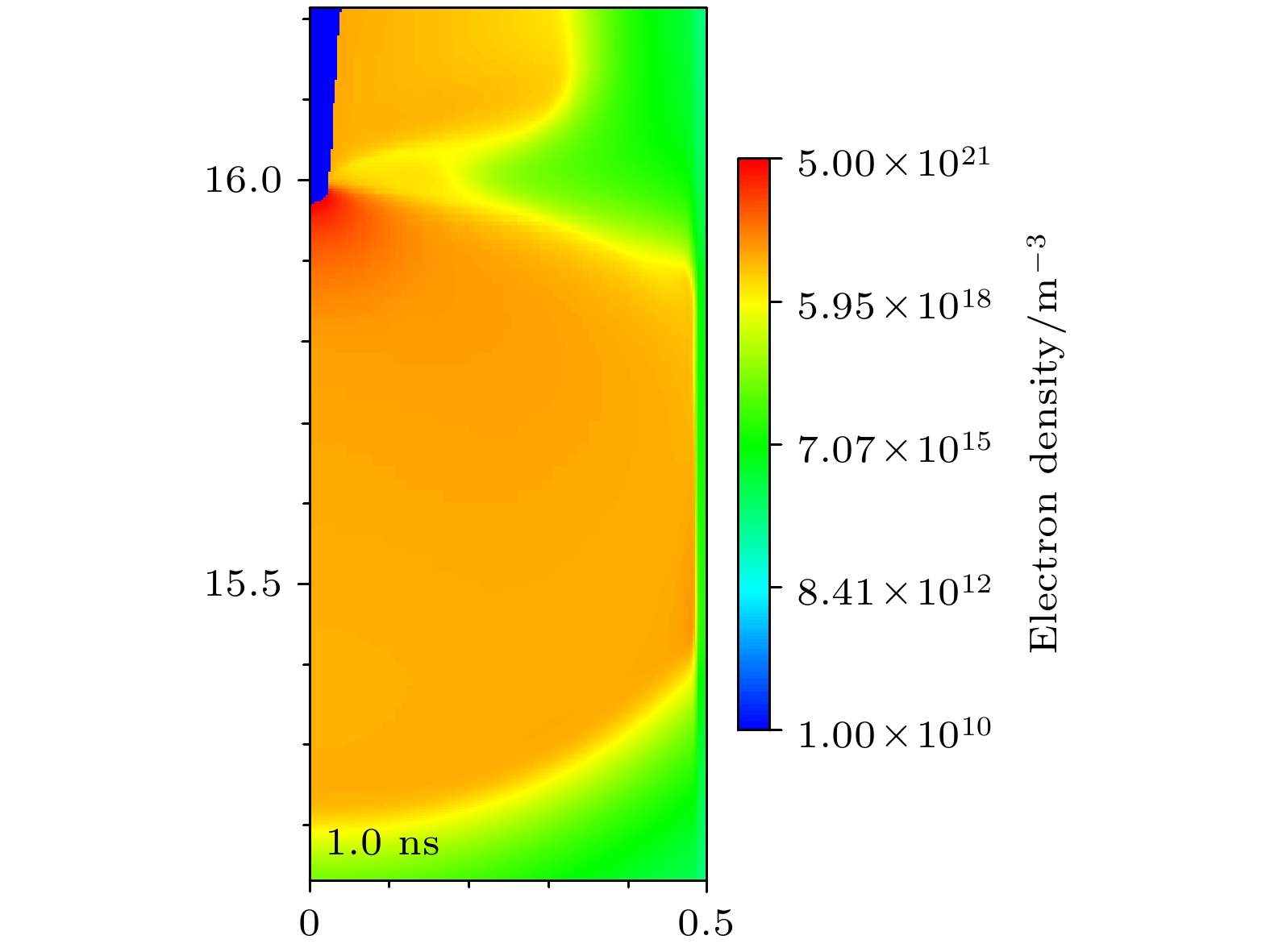
图 11 将等离子体边界范围缩减至0.5 cm时对放电计算结果造成的影响
Fig. 11. Impact of plasma boundary reduction to 0.5 cm on discharge simulation results.
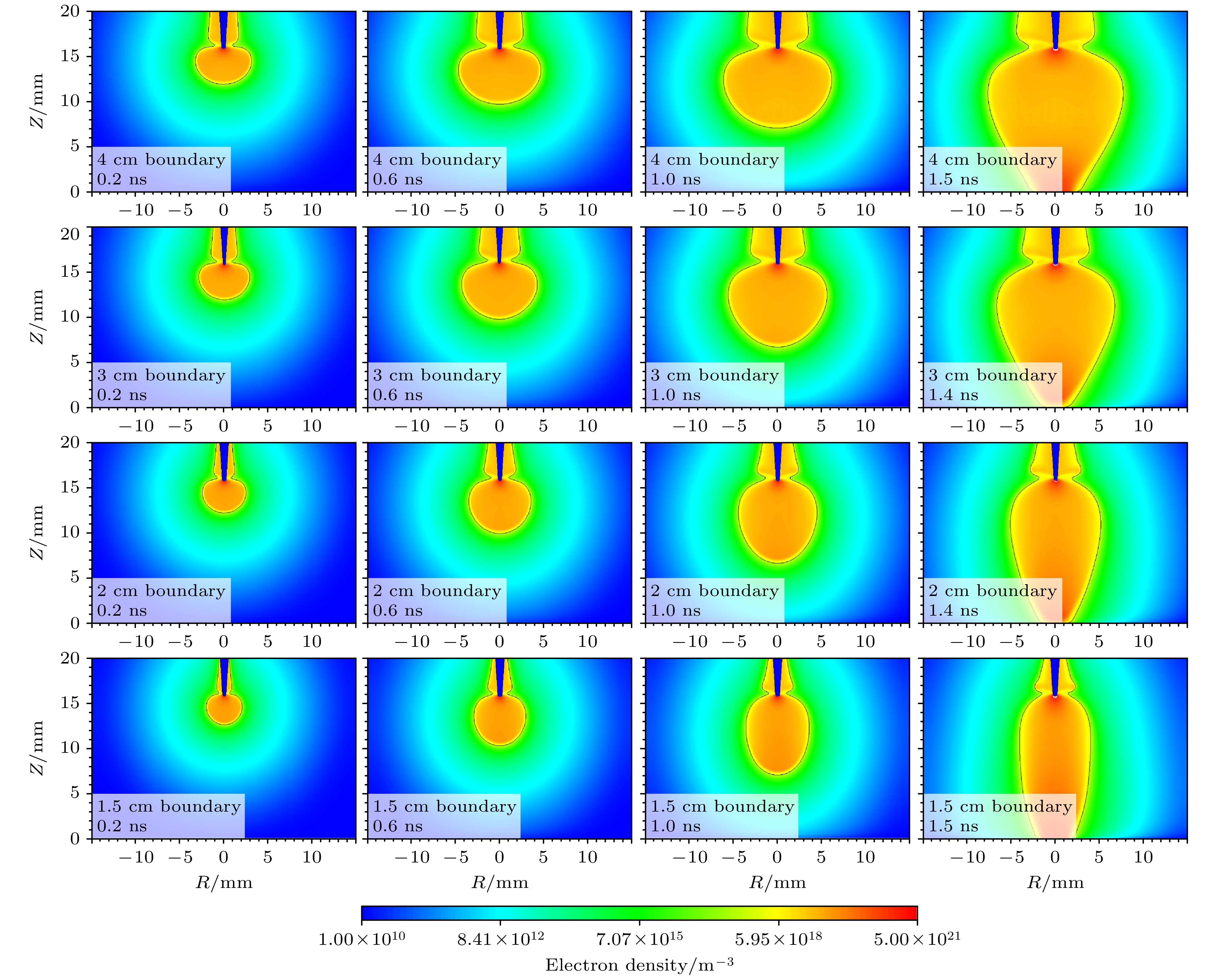
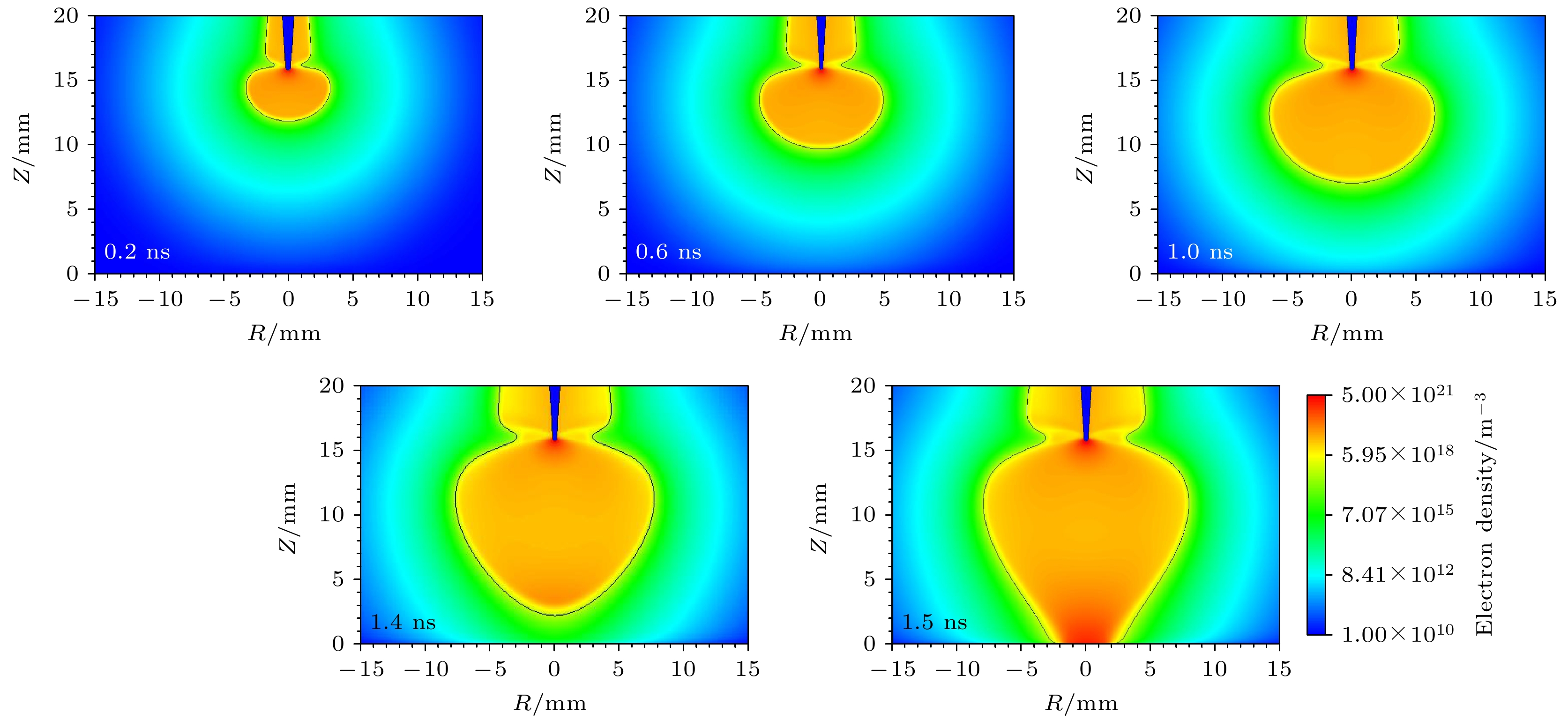
图 12 不同泊松方程边界范围条件下的放电电子密度演化过程
Fig. 12. Electron density evolution process under different boundary range of Possion’s equation.
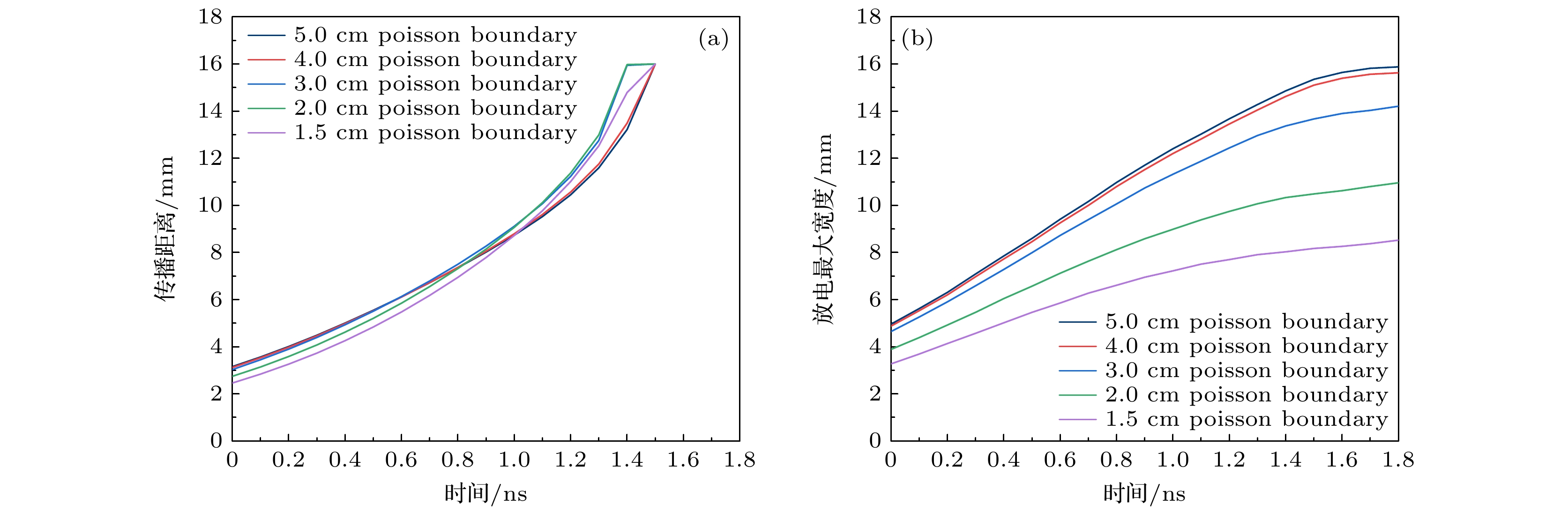
图 13 不同泊松方程边界范围下放电特性的变化规律 (a)放电传播距离; (b)放电最大宽度
Fig. 13. Discharge characteristics under different boundary range of Possion’s equation: (a) Discharge length; (b) discharge width.
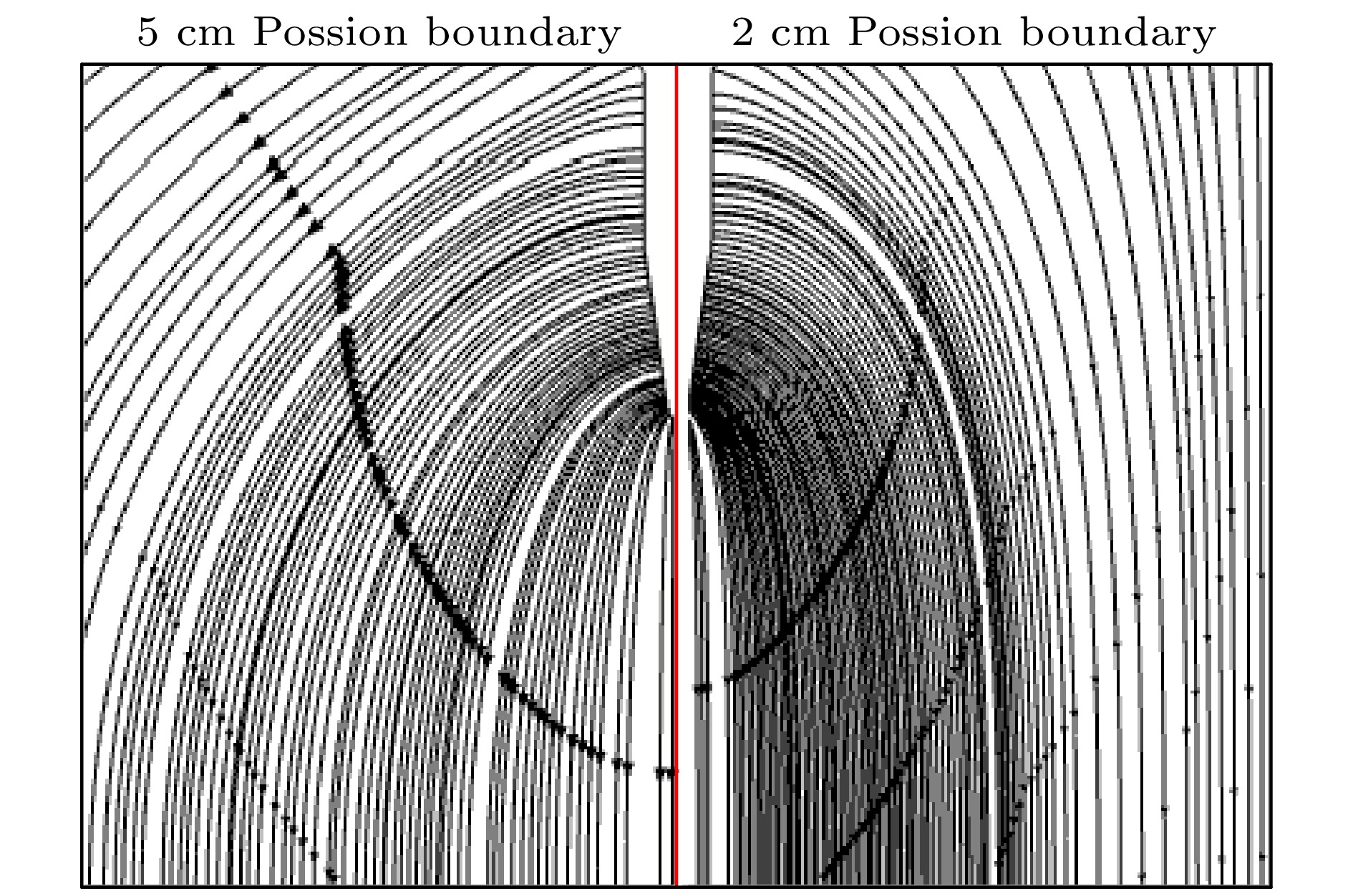
图 14 不同泊松边界范围下放电通道附近的拉普拉斯场电场线分布示意图
Fig. 14. Schematic diagram of the distribution of Laplace electric field lines near the discharge channel under different boundary ranges of Possion’s equation.
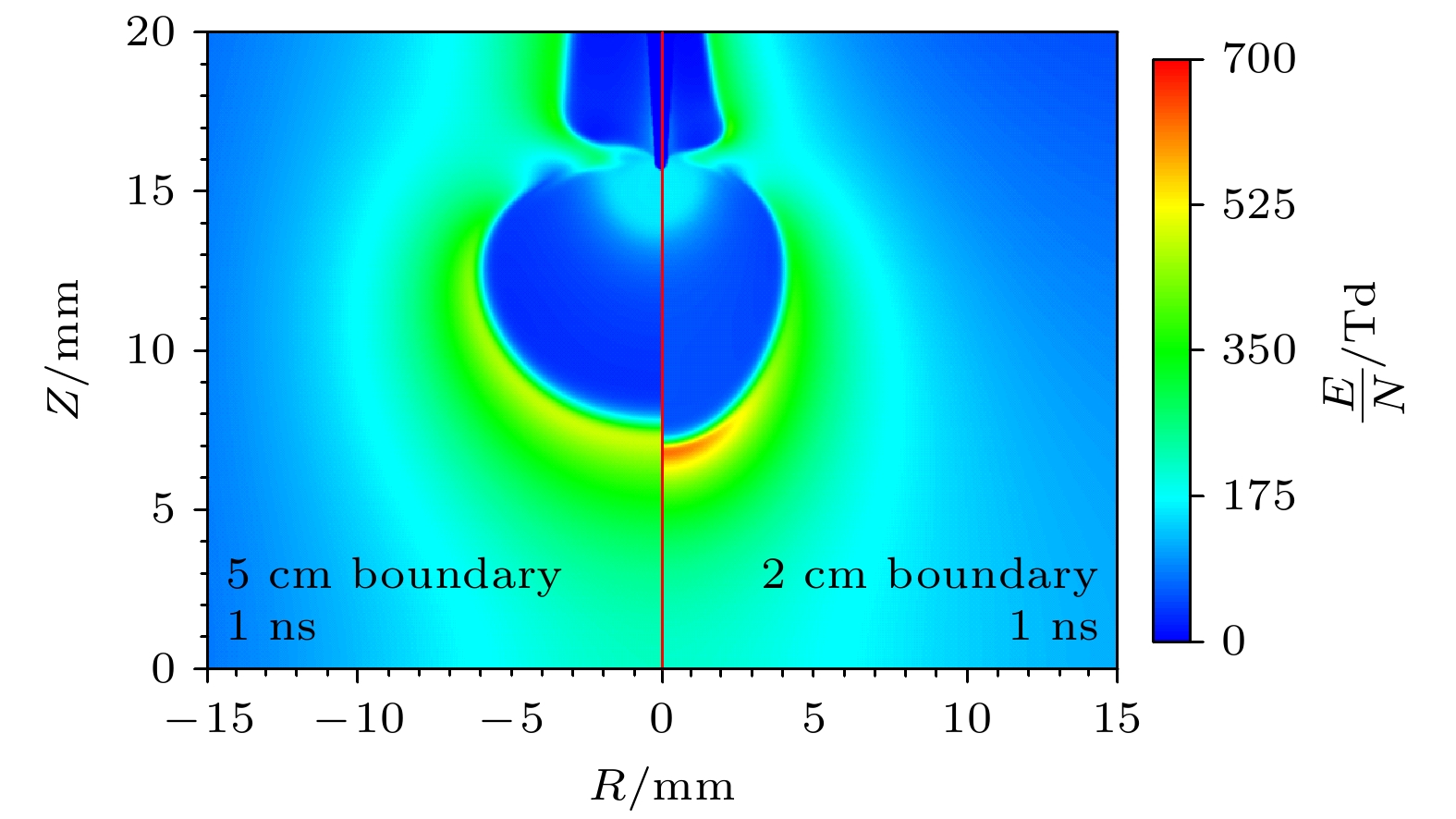
图 15 不同泊松方程边界范围下于t = 1 ns时的空间约化电场分布
Fig. 15. Reduced electric field distribution at t = 1 ns under different boundary ranges of Poisson’s equation.
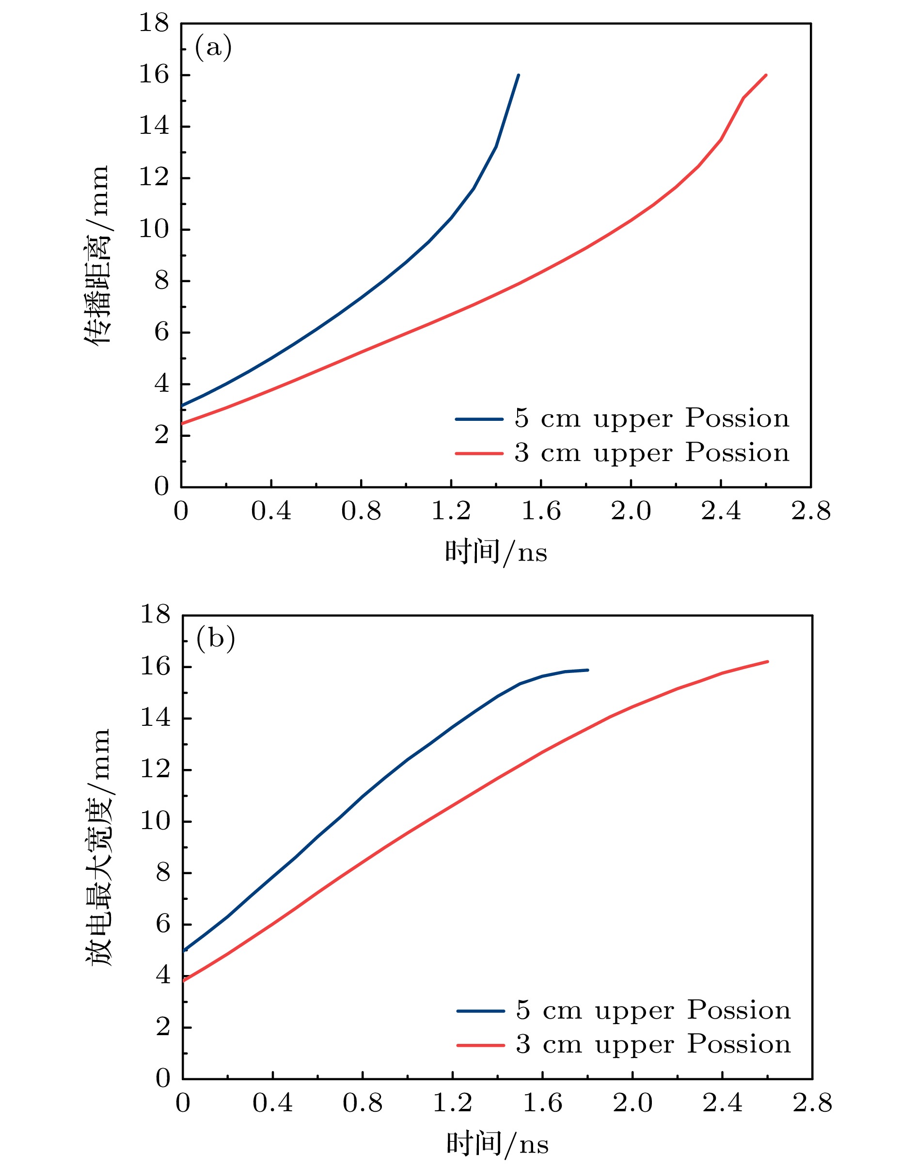
图 16 缩短泊松方程的上边界后放电发展过程中放电特性变化 (a)放电传播距离; (b)放电最大宽度
Fig. 16. Changes in discharge characteristics during discharge development after shortening the upper boundary of the Poisson’s equation: (a) Discharge length; (b) discharge width.
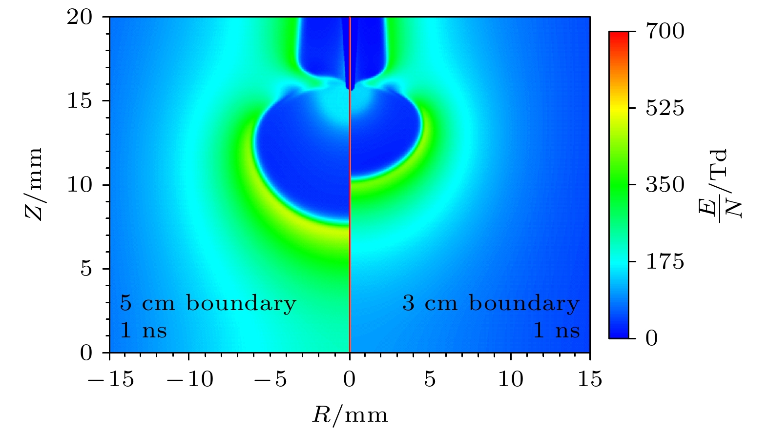
图 17 缩短泊松方程的上边界后于t = 1 ns时刻下的空间约化电场分布
Fig. 17. Reduced electric field distribution at t = 1 ns after shortening the upper boundary of the Poisson’s equation.

图 18 最大放电半径和泊松边界范围的比值
Fig. 18. Ratio of maximum discharge radius to Poisson’s equation boundary.
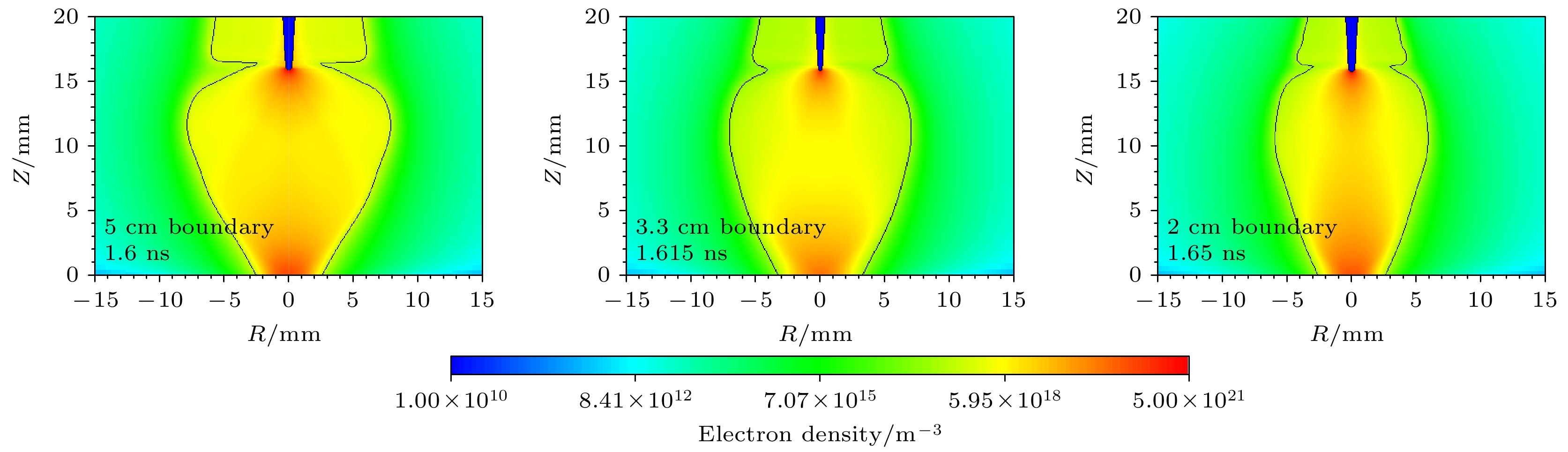
图 19 调转针电极电压极性后5 cm泊松边界和2 cm泊松边界计算结果对比
Fig. 19. Comparison of simulation results for 5 cm and 2 cm Poisson’s equation boundary after reversing the needle electrode voltage polarity.
表 1 仿真中所采用的等离子体边界条件
Table 1. Plasma boundary conditions used in the simulation.
通量方向 电子 正离子 负离子 电子能量 阳极向外 0 $ \nabla n = 0 $ 0 0 阳极向内 $ \nabla n = 0 $ 0 $ \nabla n = 0 $ $ \varGamma = {\varGamma _{\text{e}}}{n_{{\varepsilon }}} $ 阴极向外 $ \nabla n = 0 $ 0 $ \nabla n = 0 $ $ \varGamma = {\varGamma _{\text{e}}}{n_{{\varepsilon }}} $ 阴极向内 0 $ \nabla n = 0 $ 0 0  下载: 导出CSV
表 2 仿真中所采用的反应体系
Table 2. Reaction system used in simulation.
反应 反应速率 文献 R1 e+N2$ \to {\text{N}}_{2}^{+} $+e+e f(σ, ε) [16] R2 e+O2$ \to {\text{O}}_{2}^{+} $+e+e f(σ, ε) [17] R3 e+O2+O2$ \to {\text{O}}_{2}^{-} $+O2 f(ε) [17] R4 e+O2$ \to $O–+O f(ε) [17] R5 $ {\text{O}}_{2}^{-} $+M $ \to $e+O2+M f(ε) [18] R6 O–+ N2$ \to $e+N2O f(ε) [18] R7 O–+ O2$ \to {\text{O}}_{2}^{-} $+O2 f(ε) [18] R8 O–+O2+M $ \to {\text{O}}_{3}^{-} $+M f(ε) [18] R9 $ {\text{N}}_{2}^{+} $+N2+M $ \to {\text{N}}_{4}^{+} $+M $5 \times 10^{-29} \times \Big(\dfrac{300}{T_{\rm gas}}\Big)^2 $ [19] R10 $ {\text{O}}_{2}^{+} $+O2+M $ \to {\text{O}}_{4}^{+} $+M $2.4 \times 10^{-30} \times \Big(\dfrac{300}{T_{\rm gas}}\Big)^3 $ [19] R11 $ {\text{N}}_{4}^{+} + {\mathrm{O}}_2 \to {\text{O}}_{2}^{+} + {\mathrm{N}}_2 + {\mathrm{N}}_2$ 2.5×10⁻¹⁰ [19] R12 e+$ {\text{O}}_{4}^{+}\to $O2+O2 $1.4 \times 10^{-6} \times \Big(\dfrac{300}{T_{\rm gas}}\Big)^{0.5} $ [19] R13 e+$ {\text{N}}_{4}^{+}\to $N2+N2 $2 \times 10^{-6} \times \Big(\dfrac{300}{T_{\rm gas}}\Big)^{0.5} $ [19] R14 e+N2$ \to $e+ N2(C3Πu) f(ε) [16] R15 N2(C3Πu) $ \to $N2+hv 2.38×10⁷ [20] R16 $ {\text{N}}_{2}^{+} $+ O–$ \to $N+N+O 10–7 [19] R17 $ {\text{N}}_{2}^{+} $+$ {\text{O}}_{2}^{-}\to $N+N+O2 10–7 [19] R18 $ {\text{N}}_{2}^{+} $+$ {\text{O}}_{3}^{-}\to $N+N+O3 10–7 [19] R19 $ {\text{O}}_{2}^{+} $+ O–$ \to $O+O+O 10–7 [19] R20 $ {\text{O}}_{2}^{+} $+$ {\text{O}}_{2}^{-}\to $O+O+O2 10–7 [19] R21 $ {\text{O}}_{2}^{+} $+$ {\text{O}}_{3}^{-}\to $O+O+O3 10–7 [19] R22 $ {\text{O}}_{4}^{+} $+ O–$ \to $O2+O2+O 10–7 [19] R23 $ {\text{O}}_{4}^{+} + {\text{O}}_{2}^{-} \to {\mathrm{O}}_2 + {\mathrm{O}}_2 + {\mathrm{O}}_2 $ 10–7 [19] R24 $ {\text{O}}_{4}^{+} + {\text{O}}_{3}^{-} \to {\mathrm{O}}_2 + {\mathrm{O}}_2 + {\mathrm{O}}_3 $ 10–7 [19] R25 $ {\text{N}}_{4}^{+} $+ O–$ \to $N2+N2+O 10–7 [19] R26 $ {\text{N}}_{4}^{+} + {\text{O}}_{2}^{-}\to {\mathrm{N}}_2 + {\mathrm{N}}_2 + {\mathrm{O}}_2 $ 10–7 [19] R27 $ {\text{N}}_{4}^{+} + {\text{O}}_{3}^{-}\to {\mathrm{N}}_2 + {\mathrm{N}}_2 + {\mathrm{O}}_3 $ 10–7 [19]
下载: 导出CSV
-
[1] Chng T L, Pai D Z, Guaitella O, Starikovskaia S M, Bourdon A 2022 Plasma Sources Sci. Techn. 31 015010
Google Scholar
[2] Brisset A, Guenin T, Tardiveau P, Sobota A 2023 Plasma Sources Sci. Techn. 32 065014
Google Scholar
[3] Babaeva N Y, Naidis G V 2016 Phys. Plasmas 23 083527
Google Scholar
[4] Nijdam S, Teunissen J, Ebert U 2020 Plasma Sources Sci. Techn. 29 103001
Google Scholar
[5] Marode E, Dessante P, Tardiveau P 2016 Plasma Sources Sci. Techn. 25 064004
Google Scholar
[6] Tardiveau P, Moreau N, Bentaleb S, Postel C, Pasquiers S 2009 J. Phys. D Appl. Phys. 42 175202
Google Scholar
[7] Babaeva N Y, Naidis G V, Tereshonok D V, Son E E 2018 J. Phys. D Appl. Phys. 51 434002
Google Scholar
[8] Bourdon A, Péchereau F, Tholin F, Bonaventura Z 2021 J. Phys. D Appl. Phys. 54 075204
Google Scholar
[9] Bourdon A, Péchereau F, Tholin F, Bonaventura Z 2021 Plasma Sources Sci. Techn. 30 105022
Google Scholar
[10] Zhu Y F, Chen X C, Wu Y, Hao J B, Ma X G, Lu P F, Tardiveau P 2021 Plasma Sources Sci. Techn. 30 075025
Google Scholar
[11] Brisset A, Gazeli K, Magne L, Pasquiers S, Jeanney P, Marode E, Tardiveau P 2019 Plasma Sources Sci. Techn. 28 055016
Google Scholar
[12] Guo Y L, Li Y R, Zhu Y F, Sun A B 2023 Plasma Sources Scie. Techn. 32 025003
Google Scholar
[13] Grubert G K, Becker M M, Loffhagen D 2009 Phys. Rev. E 80 036405
Google Scholar
[14] Bourdon A, Pasko V P, Liu N Y, Célestin S, Ségur P, Marode E 2007 Plasma Sources Sci. Techn. 16 656
Google Scholar
[15] Pancheshnyi S 2015 Plasma Sources Sci. Techn. 24 015023
Google Scholar
[16] Phelps A V, Pitchford L C 1985 Phys. Rev. A 31 2932
Google Scholar
[17] Lawton S A, Phelps A V 1978 J. Chem. Phys. 69 1055
Google Scholar
[18] Pancheshnyi S 2013 J. Phys. D Appl. Phys. 46 155201
Google Scholar
[19] Kossyi I A, Kostinsky A Y, Matveyev A A, Silakov V P 1992 Plasma Sources Sci. Techn. 1 207
Google Scholar
[20] Pancheshnyi S, Nudnova M, Starikovskii A 2005 Phys. Rev. E 71 016407
Google Scholar
[21] Li X R, Dijcks S, Nijdam S, Sun A B, Ebert U, Teunissen J 2021 Plasma Sources Sci. Techn. 30 095002
Google Scholar
[22] Li X R, Guo B H, Sun A B, Ebert U, Teunissen J 2022 Plasma Sources Science & Technology 31 065011
Google Scholar
[23] Guo B H, Li X R, Ebert U, Teunissen J 2022 Plasma Sources Sci. Techn. 31 095011
Google Scholar
[24] 李晗蔚, 孙安邦, 张幸, 姚聪伟, 常正实, 张冠军 2018 67 045101
Google Scholar
Li H W, Sun A B, Zhang X, Yao C W, Chang Z S, Zhang G J 2018 Acta Phys. Sin. 67 045101
Google Scholar
[25] Li Y T, Fu Y Y, Liu Z G, Li H D, Wang P, Luo H Y, Zou X B, Wang X X 2022 Plasma Sources Sci. Techn. 31 045027
Google Scholar
[26] 章程, 马浩, 邵涛, 谢庆, 杨文晋, 严萍 2014 63 085208
Google Scholar
Zhang C, Ma H, Shao T, Xie Q, Yang W J, Yan P 2014 Acta Phys. Sin. 63 085208
Google Scholar
[27] Shao T, Tarasenko V F, Yang W J, Beloplotov D V, Zhang C, Lomaev M I, Yan P, Sorokin D A 2014 Chin. Phys. Lett. 31 085201
Google Scholar


 下载:
下载:


计量
- 文章访问数: 341
- PDF下载量: 12
- 被引次数: 0
