-
Multifunctional device is powerful for promoting the development of a new generation of electromagnetic systems, and the metasurface has attracted much attention in this field due to its flexible control of amplitude, phase, and polarization of the electromagnetic wave. It is very important to achieve different and arbitrary phase distributions for left-handed and right-handed circularly polarized waves in designing circularly polarized lenses. Here, a strategy to control the propagating phase and the geometrical phase simultaneously and independently is proposed by using a gap-loaded ring-shaped composite element. Through adjusting the arm length and the orientation of the unit cell, the propagating phase and geometric phase for the circularly polarized electromagnetic wave can be controlled independently. The combination of above two phases is used to break the inherent relationship between the left-handed and right-handed circularly polarized electromagnetic wave, which provides a new method of designing bifunctional devices for circular polarization. On this basis, a circularly polarized deflector with reflections in different planes and a generator with directional and vortex-shape beams are built by using the proposed composite elements. Simulated and measured results show that the bifunctional devices for circular polarization proposed in this paper can work well in a wide frequency range of 9–13 GHz. -
Keywords:
- composite metasurface /
- bifunction /
- circular polarization /
- propagating phase /
- geometric phase
[1] 杨帆, 许慎恒, 刘骁 杨雪 潘笑天 王敏 肖钰 李懋坤 2018 电波科学学报 33 256
Yang F, Xu S H, Liu X, Yang X, Pan X T, Wang M, Xiao Y, Li M K 2018 Chin. J. Radio Sci. 33 256
[2] Yu N F, Genevet P, Kats M A, Aieta F, Tetienne J P, Capasso F, Gaburro Z 2011 Science 334 333
 Google Scholar
[3] Sun S L, Yang K Y, Wang C M, Juan T K, Chen T K, Liao C Y, He Q, Xiao S Y, Kung W T, Guo G Y, Zhou L, Tsai D P 2012 Nano Lett. 12 6223
 Google Scholar
[4] Ni X, Emani N K, Kildishev A V, Boltasseva A, Shalaev V M 2012 Science 335 427
 Google Scholar
[5] Pors A, Nielsen M G, Eriksen R L, Bozhevolnyi S I 2013 Nano Lett. 13 829
 Google Scholar
[6] Li X, Xiao S Y, Cai B G, He Q, Cui T J, Zhou L 2012 Opt. Lett. 37 4940
 Google Scholar
[7] Aieta F, Genevet P, Kats M A, Yu N F, Blanchard R, Gaburro Z, Capasso F 2012 Nano Lett. 12 4932
 Google Scholar
[8] 郭文龙, 王光明, 李海鹏, 侯海生 2016 65 074101
 Google Scholar
Guo W L, Wang G M, Li H P, Hou H S 2016 Acta Phys. Sin. 65 074101
 Google Scholar
[9] Sun S L, He Q, Xiao S Y, Xu Q, Li X, Zhou L 2012 Nat. Mater. 11 426
 Google Scholar
[10] Wu C J, Cheng Y Z, Wang W Y, He B, Gong R Z 2015 Appl. Phys. Express 8 122001
 Google Scholar
[11] Zhao J M, Sima B Y, Jia N, Wang C, Zhu B, Jiang T, Fe ng, Y J 2016 Opt. Express 24 27849
 Google Scholar
[12] Song Y C, Ding J, Guo C J, Ren Y H, Zhang J K 2016 IEEE Antennas Wirel. Propag. Lett. 15 329
 Google Scholar
[13] Liu Y, Li K, Jia Y T, Hao Y W, Gong S X, Guo Y J 2016 IEEE Trans. Antennas Propag. 64 326
 Google Scholar
[14] Song K, Liu Y H, Luo C R, Zhao X P 2014 J. Phys. D: Appl. Phys. 47 505104
 Google Scholar
[15] Yu S X, Li L, Shi G M, Zhu C, Zhou X X, Shi Y 2016 Appl. Phys. Lett. 108 121903
 Google Scholar
[16] Liu K Y, Guo W L, Wang G M, Li H P, Liu Gang 2018 IEEE Access 6 63999
 Google Scholar
[17] Li H P, Wang G M, Cai T, Liang J G, Gao X J 2018 IEEE Trans. Antennas Propag. 66 5121
 Google Scholar
[18] Li H P, Wang G M, Cai T, Hou H S, Guo W L 2019 Phys. Rev. Appl. 11 014043
 Google Scholar
[19] Cai T, Tang S W, Wang G M, X u, H X, Sun S L, He Q, Zhou L 2017 Adv. Opt. Mater. 5 1600506
 Google Scholar
[20] Guo W L, Wang G M, Li H P, Zhuang Y Q, Shuai C Y 2017 Appl. Phys. A 123 103
 Google Scholar
[21] Qi X, Zhang Z Y, Zong X Z, Que X F, Nie Z P, Hu J 2019 Sci. Rep. 9 97
 Google Scholar
[22] Arbabi E, Arbabi A, Kamali S M, Horie Y, Faraon A 2016 Opt. Express 24 18468
 Google Scholar
[23] Ling Y, Huang L, Hong W. Liu T. Jing L, Liu W, Wang Z 2017 Opt. Express 25 29812
 Google Scholar
[24] Huang L L, Mühlenbernd H, Li X W, Song Y, Bai B F, Wang Y T, Zentgraf T 2015 Adv. Mater. 27 6444
 Google Scholar
[25] Li Z C, Liu W W, Cheng H, Liu J Y, Chen S Q, Tian J G 2016 Sci. Rep. 6 35485
 Google Scholar
[26] Wang Z J, Jia H, Yao K, Cai W S, Chen H S, Liu Y M 2016 ACS Photonics 3 2096
 Google Scholar
-
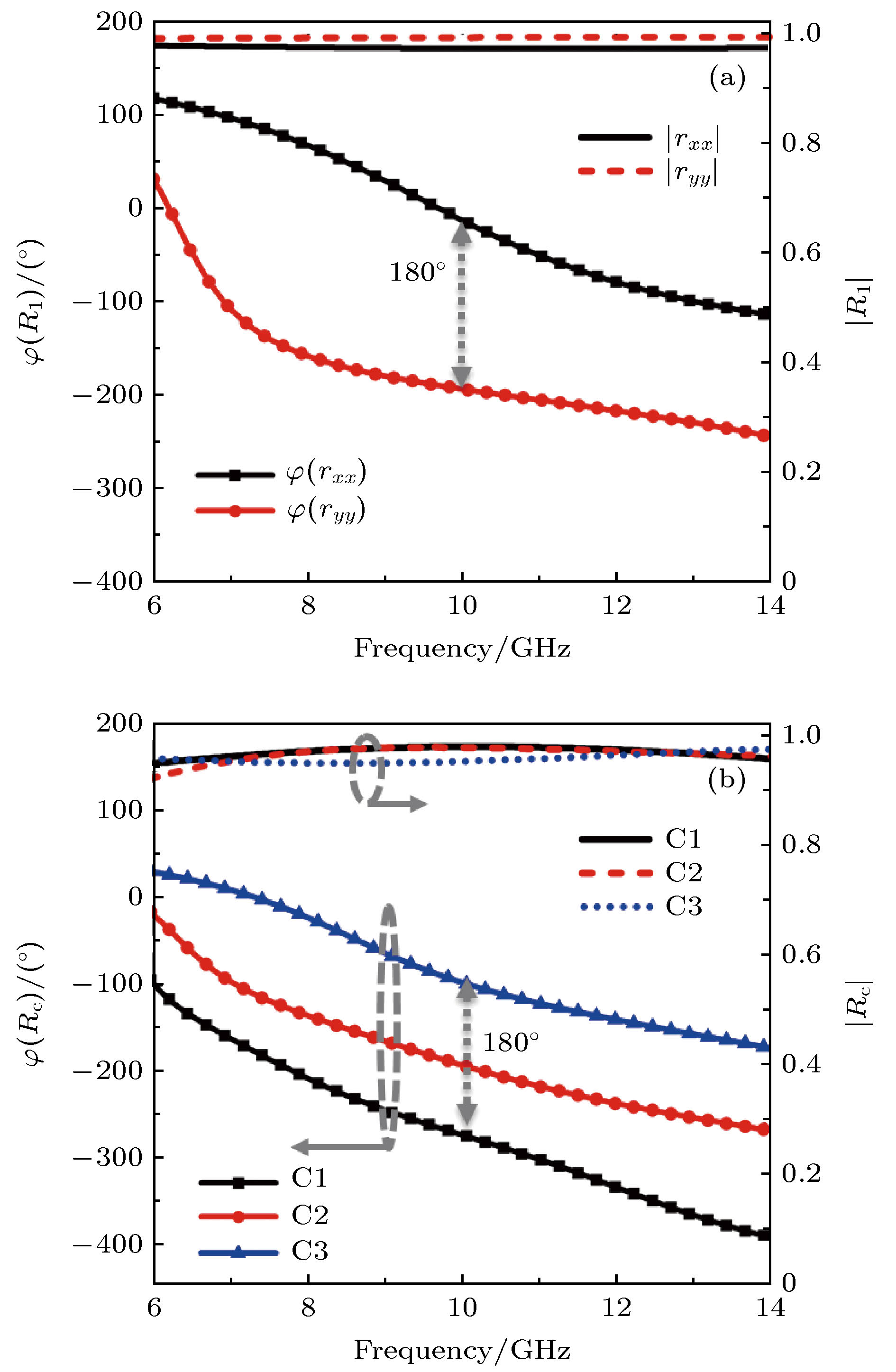
图 4 复合超构表面单元反射系数随参数的变化曲线 (a) 10 GHz处, C1, C2和C3单元随旋转角β变化的幅度和相位曲线; (b) 10 GHz处, β = 0°时, 单元传输相位随α变化的幅度和相位曲线
Figure 4. The curves of the reflection coefficient versus structural parameters for unit cells: (a) The curves of the amplitude and phase versus β for C1, C2, and C3 at 10 GHz; (b) the curves of the propagating phase and amplitude versus α at 10 GHz and β = 0°.
图 5 线性阵列的相位分布、仿真结果及模型 (a) 左旋、右旋、传输和几何相位的线性分布; (b)左旋和右旋反射波的归一化远场方向图; (c)阵列模型
Figure 5. The phase distribution, simulated results and model of the linear array: (a) Linear distribution of left-handed, right-handed, propagating and geometric phase; (b) normalized far-field patterns of left-hand and right-hand reflected waves; (c) model of the linear array.
图 8 圆极化异面偏折器仿真及测试 (a) 仿真模型; (b) 总能量在10 GHz处的三维仿真远场方向图; (c) 暗室测试示意图
Figure 8. Model and total power farfield radiation pattern of the circularly polarized deflector with reflections in different planes: (a) Simulated model; (b) three-dimensional farfield radiation pattern of total power at 10 GHz.; (c) schematic of the measurement in the anechoic chamber.
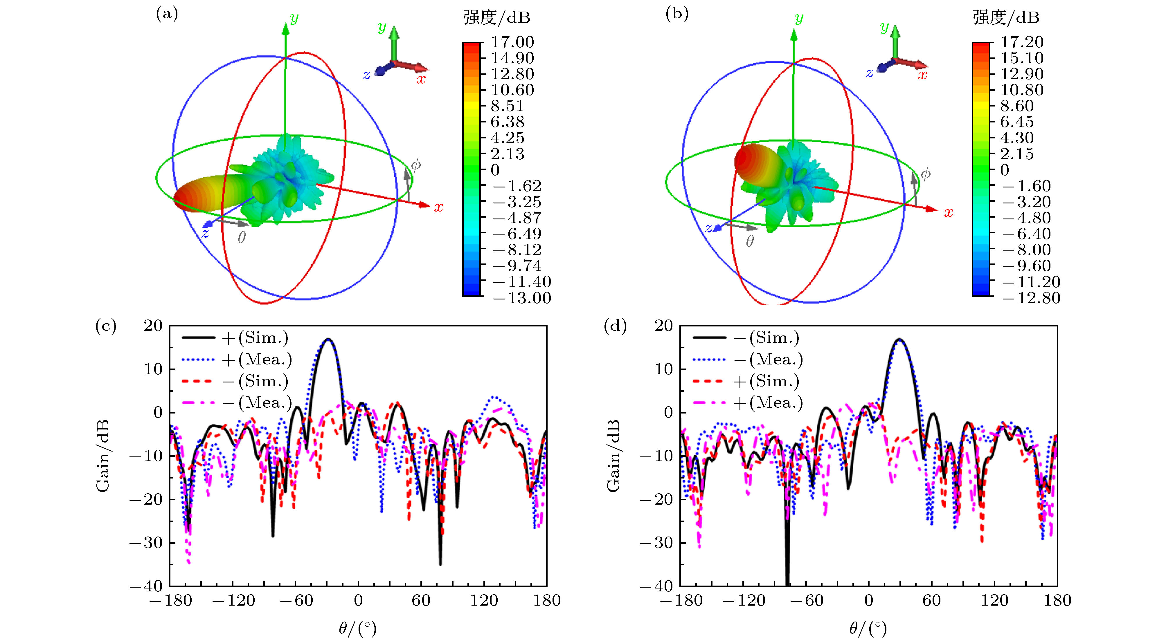
图 9 异面偏折器右旋和左旋分量的远场方向图. 仿真三维方向图 (a) 右旋; (b) 左旋. 仿真和测试二维方向图 (c) xoz面; (d) yoz面
Figure 9. Farfield radiation patterns of right-handed and left-handed components. Simulated three-dimensional patterns of (a) right-handed component and (b) left-handed component. Simulated and measured two-dimensional patterns on (c) xoz and (d) yoz plane.
图 10 异面偏折器在其他频点处的三维总能量仿真远场方向图 (a) 8 GHz; (b) 9 GHz; (c) 11 GHz; (d) 12 GHz; (e) 13 GHz; (f) 14 GHz
Figure 10. Simulated three-dimensional farfield radiation patterns at other frequencies for the circularly polarized deflector with reflections in different planes: (a) 8 GHz; (b) 9 GHz; (c) 11 GHz; (d) 12 GHz; (e) 13 GHz; (f) 14 GHz.
图 11 异面偏折器的二维方向图随频率变化谱图(红色★为理论计算值) (a) xoz面; (b) yoz面
Figure 11. Maps of the two-dimensional far-field pattern versus frequency on different planes for the circularly polarized deflector with reflections on different planes: (a) xoz plane; (b) yoz plane (The symbols marked by red ★ are the theoretical values).
图 12 定向和涡旋光束产生器的相位分布 (a) 右旋相位分布; (b) 左旋相位分布; (c) 传输相位分布; (d) 几何相位分布
Figure 12. Phase distributions of the circularly polarized generator with directional and vortex-shape beams: (a) Right-handed circular polarization; (b) left-handed circular polarization; (c) propagating phase; (d) geometric phase.
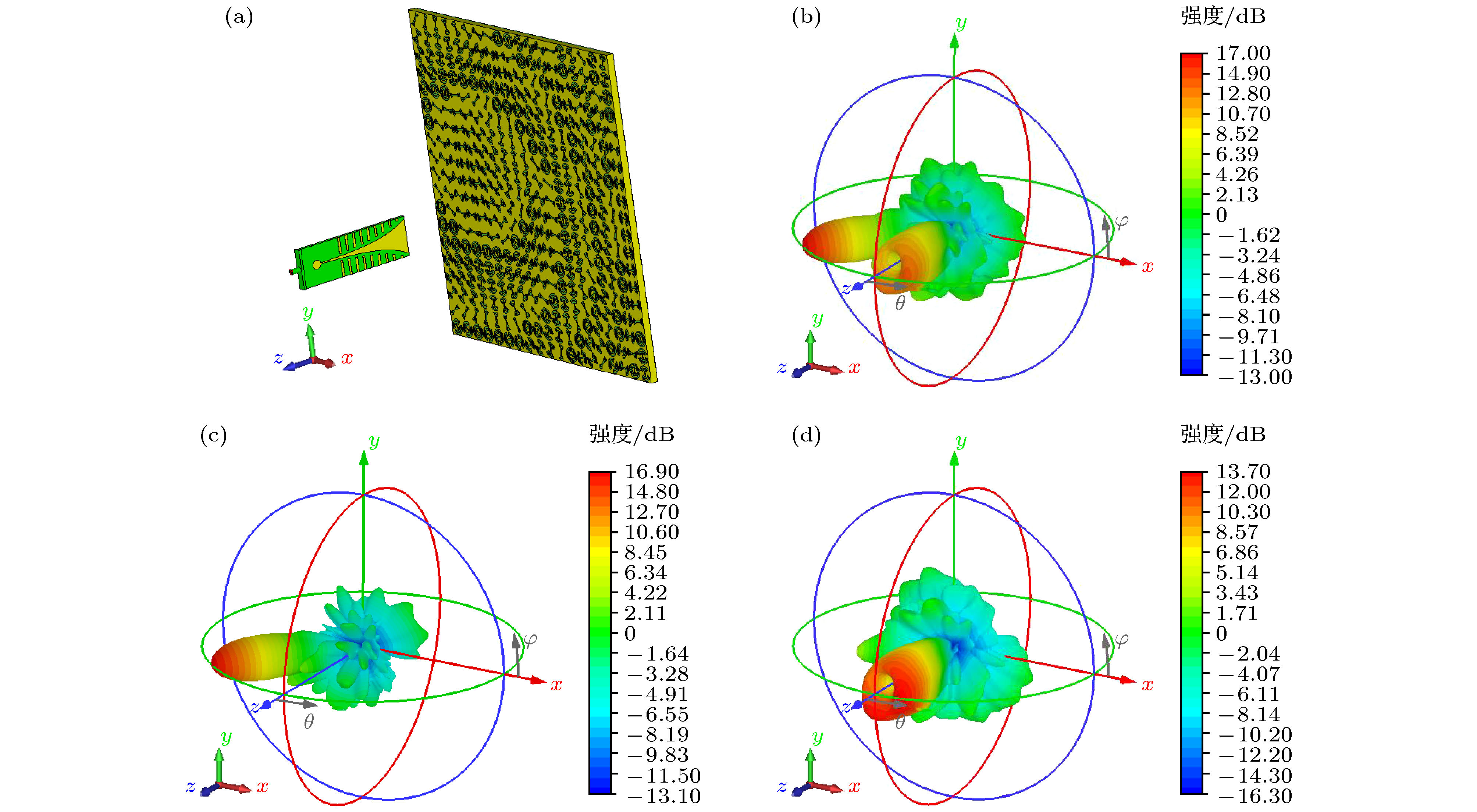
图 13 定向和涡旋光束产生器的模型和三维仿真方向图 (a) 模型; 10 GHz处的总能量(b), 右旋分量(c); 左旋分量(d)的三维远场方向图
Figure 13. Model and radiation patterns of the circularly polarized generator with directional and vortex-shape beams: (a) Simulation model; three-dimensional patterns of the total power (b), right-handed component (c), and (d) left-handed component at 10 GHz.
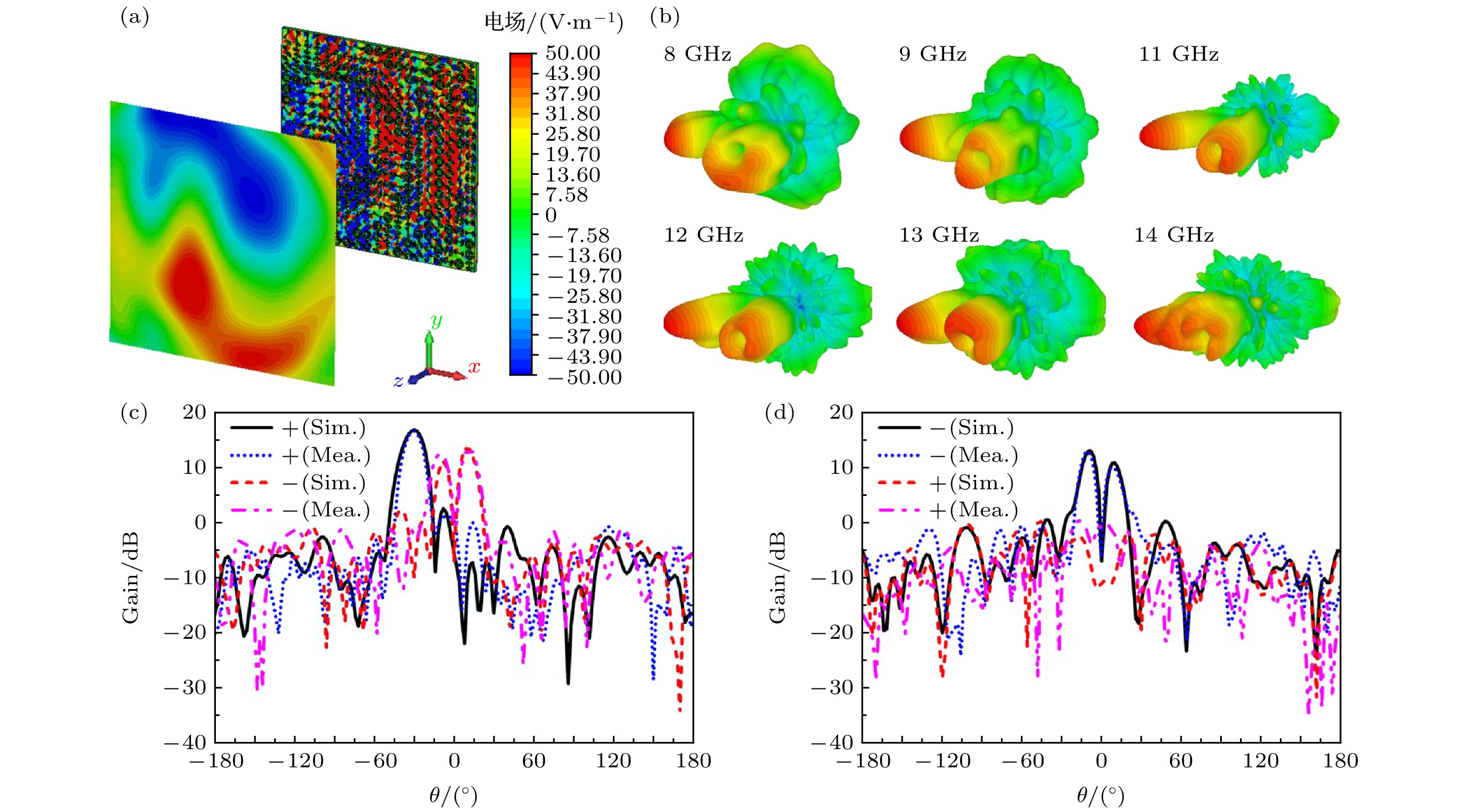
图 14 (a) x极化电场分量在10 GHz处的涡旋近场分布; (b) 其他频点处的三维总能量仿真远场方向图; (c) xoz面和(d) yoz面的仿真和测试二维远场方向图
Figure 14. (a) The x-component electric field distribution at 10 GHz; (b) three-dimensional farfield radiation patterns at other frequencies. Simulated and measured two-dimensional radiation patterns on xoz-plane (c) and yoz-plane (d) at 10 GHz.
-
[1] 杨帆, 许慎恒, 刘骁 杨雪 潘笑天 王敏 肖钰 李懋坤 2018 电波科学学报 33 256
Yang F, Xu S H, Liu X, Yang X, Pan X T, Wang M, Xiao Y, Li M K 2018 Chin. J. Radio Sci. 33 256
[2] Yu N F, Genevet P, Kats M A, Aieta F, Tetienne J P, Capasso F, Gaburro Z 2011 Science 334 333
 Google Scholar
[3] Sun S L, Yang K Y, Wang C M, Juan T K, Chen T K, Liao C Y, He Q, Xiao S Y, Kung W T, Guo G Y, Zhou L, Tsai D P 2012 Nano Lett. 12 6223
 Google Scholar
[4] Ni X, Emani N K, Kildishev A V, Boltasseva A, Shalaev V M 2012 Science 335 427
 Google Scholar
[5] Pors A, Nielsen M G, Eriksen R L, Bozhevolnyi S I 2013 Nano Lett. 13 829
 Google Scholar
[6] Li X, Xiao S Y, Cai B G, He Q, Cui T J, Zhou L 2012 Opt. Lett. 37 4940
 Google Scholar
[7] Aieta F, Genevet P, Kats M A, Yu N F, Blanchard R, Gaburro Z, Capasso F 2012 Nano Lett. 12 4932
 Google Scholar
[8] 郭文龙, 王光明, 李海鹏, 侯海生 2016 65 074101
 Google Scholar
Guo W L, Wang G M, Li H P, Hou H S 2016 Acta Phys. Sin. 65 074101
 Google Scholar
[9] Sun S L, He Q, Xiao S Y, Xu Q, Li X, Zhou L 2012 Nat. Mater. 11 426
 Google Scholar
[10] Wu C J, Cheng Y Z, Wang W Y, He B, Gong R Z 2015 Appl. Phys. Express 8 122001
 Google Scholar
[11] Zhao J M, Sima B Y, Jia N, Wang C, Zhu B, Jiang T, Fe ng, Y J 2016 Opt. Express 24 27849
 Google Scholar
[12] Song Y C, Ding J, Guo C J, Ren Y H, Zhang J K 2016 IEEE Antennas Wirel. Propag. Lett. 15 329
 Google Scholar
[13] Liu Y, Li K, Jia Y T, Hao Y W, Gong S X, Guo Y J 2016 IEEE Trans. Antennas Propag. 64 326
 Google Scholar
[14] Song K, Liu Y H, Luo C R, Zhao X P 2014 J. Phys. D: Appl. Phys. 47 505104
 Google Scholar
[15] Yu S X, Li L, Shi G M, Zhu C, Zhou X X, Shi Y 2016 Appl. Phys. Lett. 108 121903
 Google Scholar
[16] Liu K Y, Guo W L, Wang G M, Li H P, Liu Gang 2018 IEEE Access 6 63999
 Google Scholar
[17] Li H P, Wang G M, Cai T, Liang J G, Gao X J 2018 IEEE Trans. Antennas Propag. 66 5121
 Google Scholar
[18] Li H P, Wang G M, Cai T, Hou H S, Guo W L 2019 Phys. Rev. Appl. 11 014043
 Google Scholar
[19] Cai T, Tang S W, Wang G M, X u, H X, Sun S L, He Q, Zhou L 2017 Adv. Opt. Mater. 5 1600506
 Google Scholar
[20] Guo W L, Wang G M, Li H P, Zhuang Y Q, Shuai C Y 2017 Appl. Phys. A 123 103
 Google Scholar
[21] Qi X, Zhang Z Y, Zong X Z, Que X F, Nie Z P, Hu J 2019 Sci. Rep. 9 97
 Google Scholar
[22] Arbabi E, Arbabi A, Kamali S M, Horie Y, Faraon A 2016 Opt. Express 24 18468
 Google Scholar
[23] Ling Y, Huang L, Hong W. Liu T. Jing L, Liu W, Wang Z 2017 Opt. Express 25 29812
 Google Scholar
[24] Huang L L, Mühlenbernd H, Li X W, Song Y, Bai B F, Wang Y T, Zentgraf T 2015 Adv. Mater. 27 6444
 Google Scholar
[25] Li Z C, Liu W W, Cheng H, Liu J Y, Chen S Q, Tian J G 2016 Sci. Rep. 6 35485
 Google Scholar
[26] Wang Z J, Jia H, Yao K, Cai W S, Chen H S, Liu Y M 2016 ACS Photonics 3 2096
 Google Scholar
Catalog
Metrics
- Abstract views: 8334
- PDF Downloads: 168
- Cited By: 0


 DownLoad:


