-
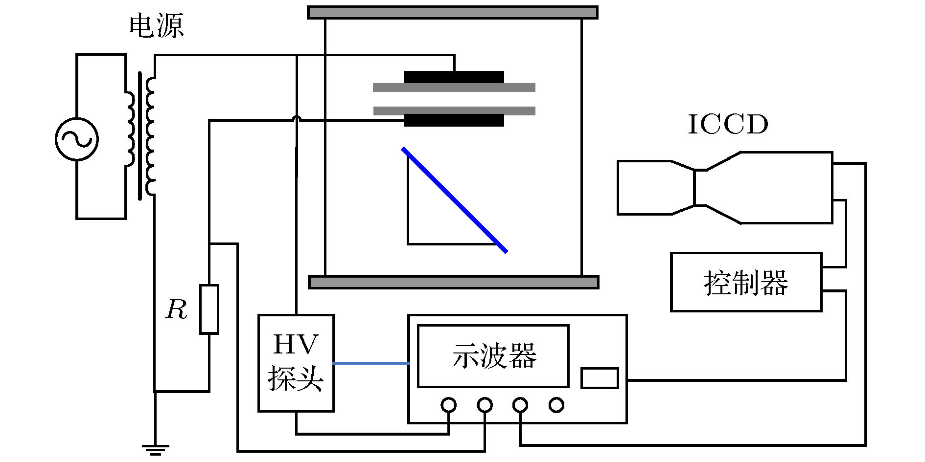
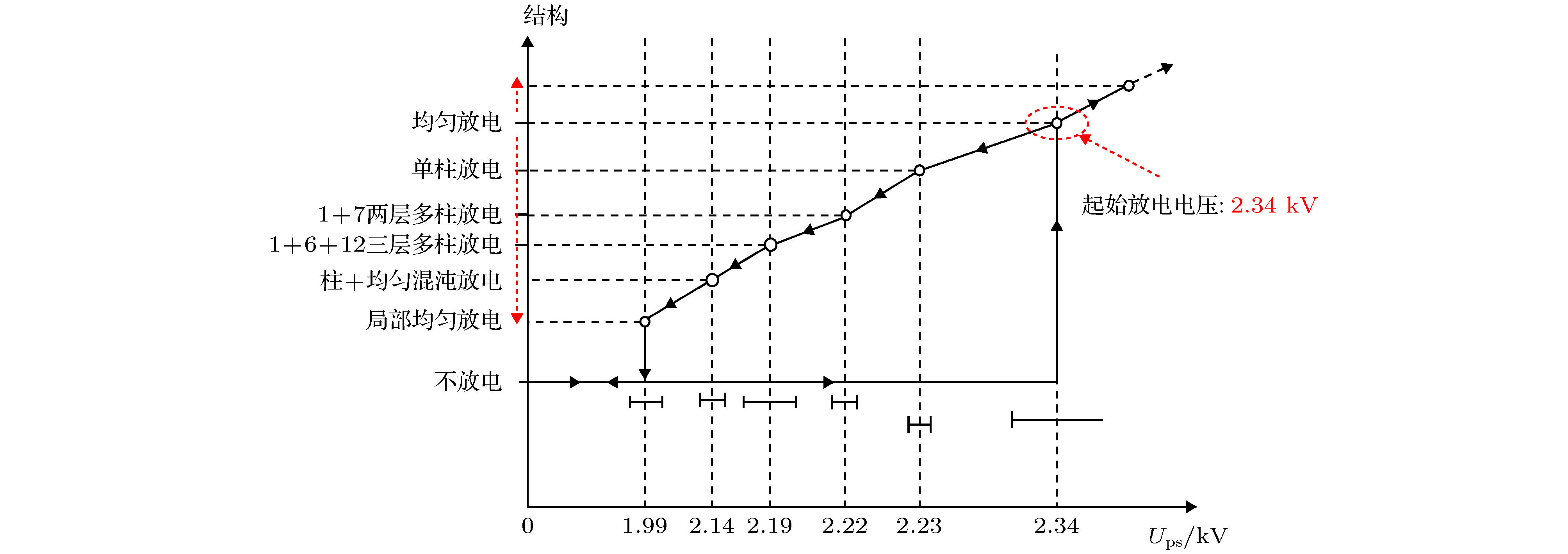
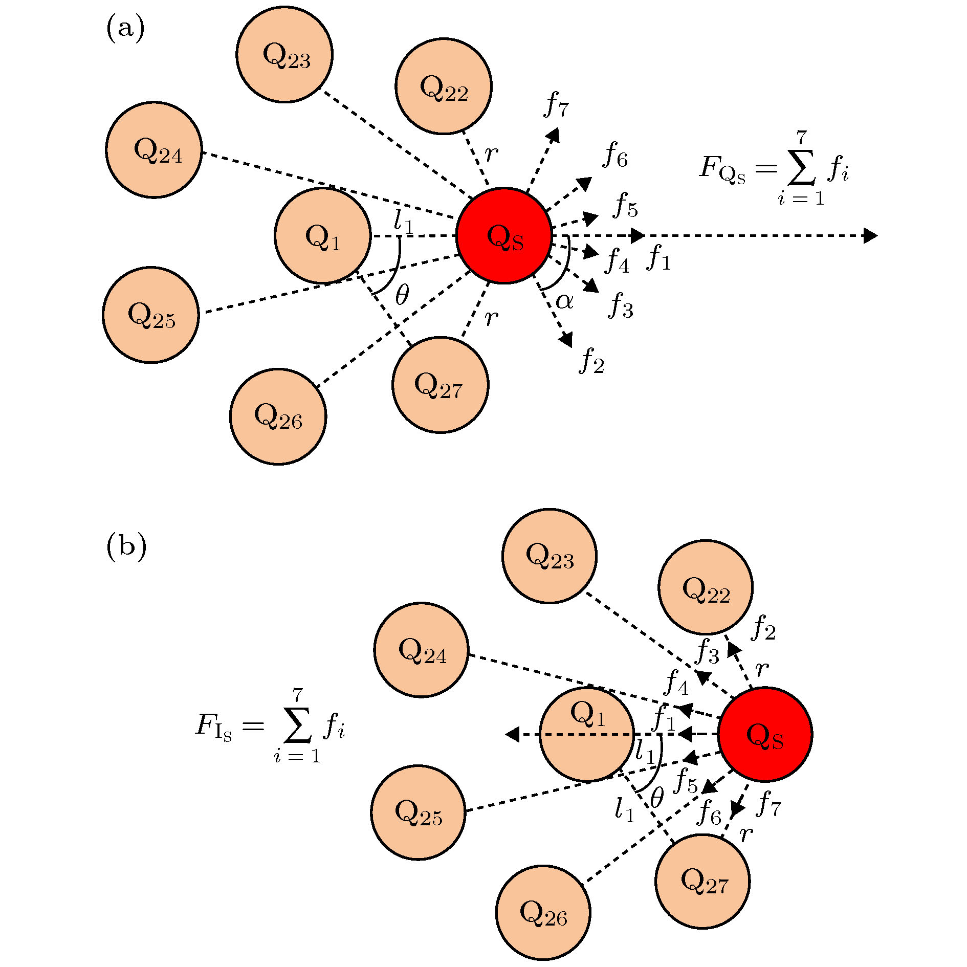
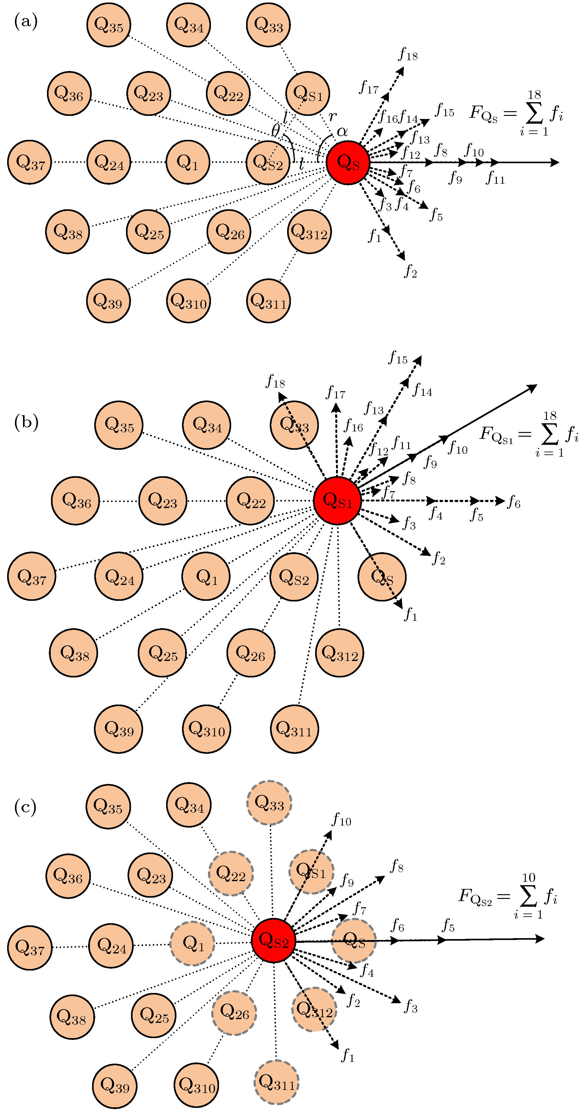
Dielectric barrier discharge is widely used as a low-temperature plasma source in industry. Columnar discharge is an important form of dielectric barrier discharge. However, its discharge theory has not been clear yet. In this paper, the dielectric barrier discharges in helium at atmospheric pressure are carried out between parallel dielectric barrier electrodes to study the evolutionary dynamics of single-multiple columns. By reducing the applied voltages to a value lower than the initial discharge voltage, the pattern of the columnar discharge evolves from a single column into multiple columns. Discharge images from the bottom are taken to observe the evolution of discharge and measure the diameter of discharge column and spacing between columns. The applied voltage, the Lissajous figure, the discharge current, and the discharge transferred charge are measured in order to calculate the Coulomb force and the magnetic field force exerted on the column by the other columns. It is found that in columnar discharge, there is a dynamic evolution process that the single columnar discharge evolves into the two-layered columnar discharge when the applied voltage slightly decreases instantaneously. On the one hand, the column diameter is different in different layer: the column diameter increases from the center to the outer layer. On the other hand, as the applied voltage decreases, the diameter of the center column grows and the spacing between the center column and its adjacent column decreases. The calculations show that the Coulomb force is far greater than the magnetic field force when the evolution is stable, which indicates that, as mentioned in the established knowledge, there is a confinement potential to balance the Coulomb force, thereby keeping the distribution of discharge columns stable. Furthermore, the results also show that the Coulomb force on the discharge columns at different voltage and position is different. The strength of Coulomb force on column is different at different layer: it decreases from the outermost layer to the center column, which is zero on the center column. Based on the balance between the Coulomb force and the confinement potential in columnar discharge, it is suggested that the strength of the latter may also follow the same law. In addition, as the applied voltage decreases, the charges accumulated on the surface of the dielectric and the number of discharge columns both increase, which results in the increase of the maximum of the Coulomb force. The confinement potential may increase as well and follow the same law.
-
Keywords:
- columnar pattern discharge /
- spatio-temporal evolution /
- coulomb force /
- confinement potential
[1] 王新新 2009 高电压技术 35 1
 Google Scholar
Wang X X 2009 High Volt. Eng. 35 1
 Google Scholar
[2] 郝艳捧, 关志成, 王黎明, 王新新, 李成榕 2005 高电压技术 31 42
 Google Scholar
Hao Y P, Guan Z C, Wang L M, Wang X X, Li C R 2005 High Volt. Eng. 31 42
 Google Scholar
[3] Ding H X, Zhu A M, Lu F G, Xu Y, Zhang J, Yang X F 2006 J. Phys. D: Appl. Phys. 39 3603
 Google Scholar
[4] Durme J V, Dewulf J, Leys C, Langenhove H V 2008 Appl. Catal. B: Environ. 78 324
 Google Scholar
[5] Kim H H 2004 Plasma Process Polym. 1 91
 Google Scholar
[6] Kogelschatz U 2002 IEEE Trans. Plasma Sci. 30 1400
 Google Scholar
[7] Golubovskii Y B, Maiorov V A, Behnke J, Behnke J F 2003 J. Phys. D: Appl. Phys. 36 39
 Google Scholar
[8] Luo H Y, Liang Z, Wang X X, Guan Z C, Wang L M 2010 J. Phys. D: Appl. Phys. 43 155201
 Google Scholar
[9] Astrov Y A, Logvin Y A 1997 Phys. Rev. Lett. 79 2983
 Google Scholar
[10] Dong L F, Shang J, He Y F, Bai Z G, Liu L, Fan W L 2012 Phys. Rev. E 85 066403
 Google Scholar
[11] 梁卓, 罗海云, 王新新, 关志成, 王黎明 2010 59 8739
 Google Scholar
Liang Z, Luo H Y, Wang X X, Guan Z C, Wang L M 2010 Acta Phys. Sin. 59 8739
 Google Scholar
[12] Mukaigawa S, Fujiwara K, Sato T, Odagiri R, Kudoh T, Yokota A, Oguni K, Takaki K 2016 Jpn. J. Appl. Phys. 55 07LB04
 Google Scholar
[13] Hao Y P, Han Y Y, Huang Z M, Yang L, Dai D, Li L C 2018 Phys. Plasmas 25 013516
 Google Scholar
[14] Radu I, Bartnikas R, Czeremuszkin G, Wertheimer M R 2003 IEEE Trans. Plasma Sci. 31 411
 Google Scholar
[15] Astrov Y A, Ammelt E, Purwins H-G 1997 Phys. Rev. Lett. 78 3129
 Google Scholar
[16] 董丽芳, 高瑞玲, 贺亚峰, 范伟丽, 李雪辰, 刘书华, 刘微粒 2007 56 1471
 Google Scholar
Dong L F, Gao R L, He Y F, Fan W L, Li X C, Liu S H, Liu W L 2007 Acta Phys. Sin. 56 1471
 Google Scholar
[17] Hao Y P, Zheng B, Liu Y G 2014 Phys. Plasmas 21 013503
 Google Scholar
[18] Müller I, Ammelt E, Purwins H-G 1999 Phys. Rev. Lett. 82 3428
 Google Scholar
[19] Hao Y P, Fang Q, Wan H R, Han Y Y, Yang L, Li L C 2019 Phys. Plasmas 26 073518
 Google Scholar
[20] Shirafuji T, Kitagawa T, Wakai T, Tachibana K 2003 Appl. Phys. Lett. 83 2309
 Google Scholar
[21] Bedanov V M, Peeters F M 1994 Phys. Rev. B 49 2667
 Google Scholar
[22] Boeuf J P, Bernecker B, Callegari T, Blanco S, Fournier R 2012 Appl. Phys. Lett. 100 244108
 Google Scholar
[23] 郝艳捧, 刘耀阁, 郑彬 2012 高电压技术 38 1025
 Google Scholar
Hao Y P, Liu Y G, Zheng B 2012 High Volt. Eng. 38 1025
 Google Scholar
[24] 郝艳捧, 阳林, 涂恩来, 陈建阳 2009 高电压技术 35 1879
 Google Scholar
Hao Y P, Yang L, Tu E L, Chen J Y 2009 High Volt. Eng. 35 1879
 Google Scholar
[25] Falkenstein Z, Coogan J J 1997 J. Phys. D: Appl. Phys. 30 817
 Google Scholar
-
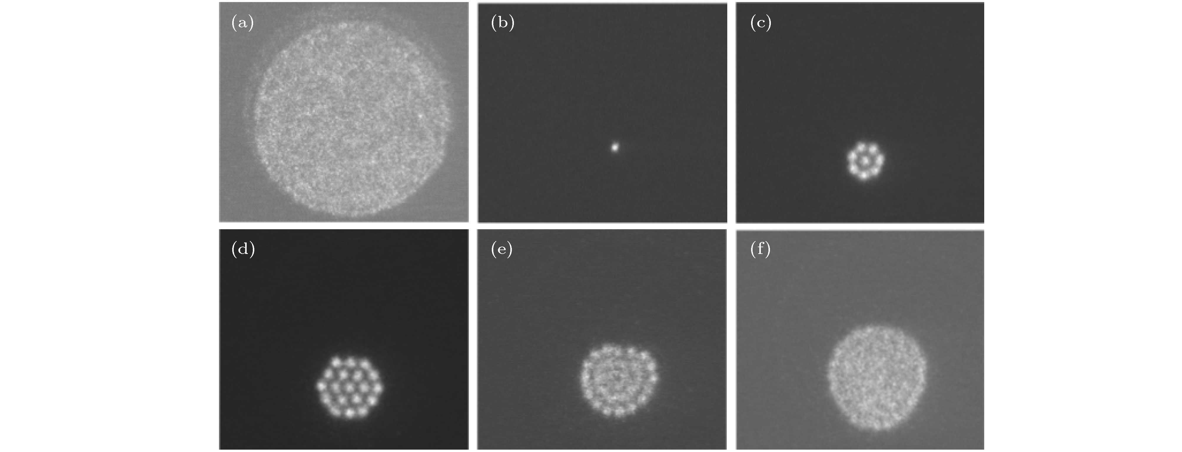
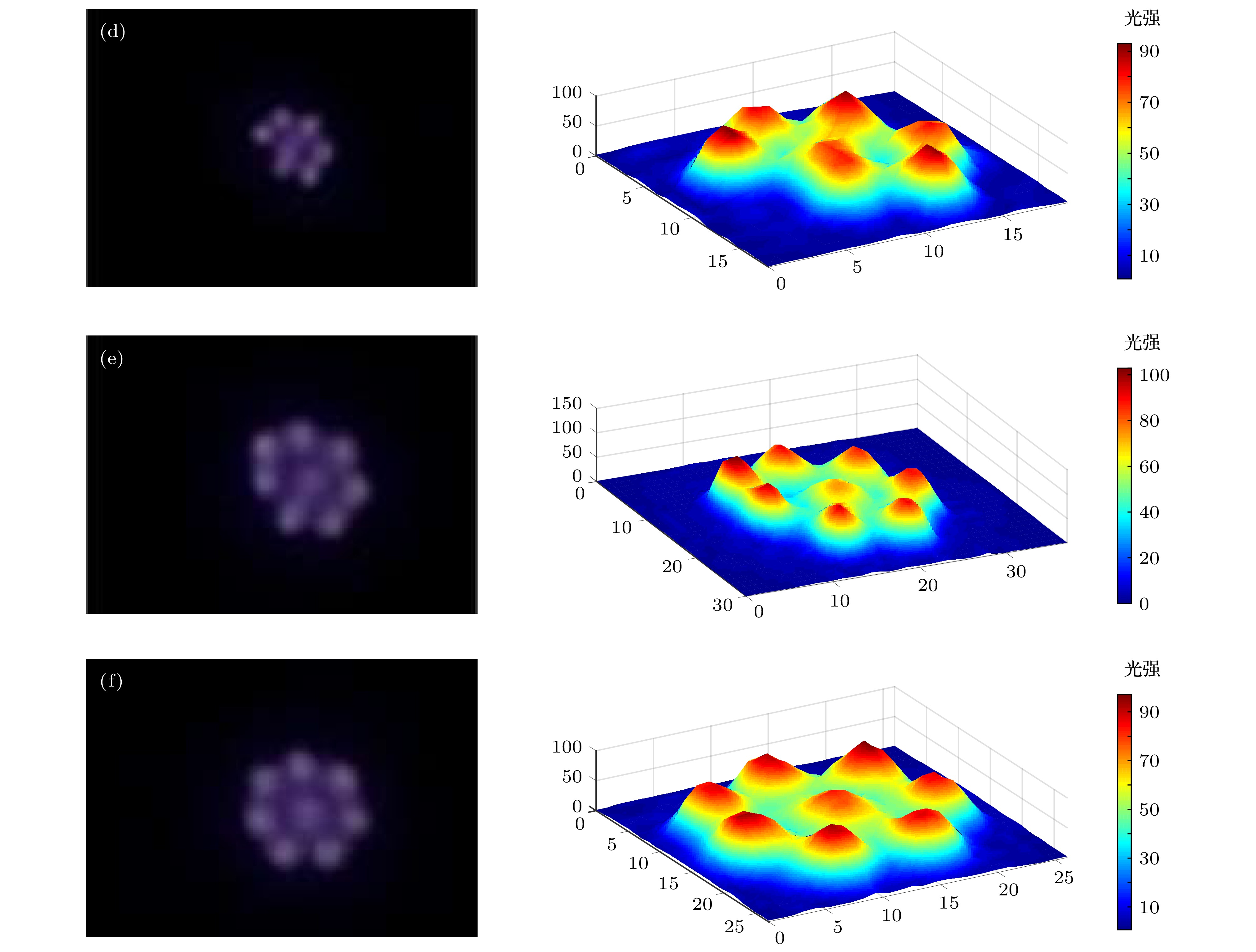
图 5 外施电压峰值由2.23 kV降至2.22 kV过程中放电形式的径向演化与光强分布 (a) t = 0, Ups = 2.23 kV → 2.22 kV; (b) t = 0.017 s; (c) t = 0.033 s; (d) t = 0.050 s; (e) t = 0.067 s; (f) t = 0.083 s
Figure 5. Radial evolution of discharge pattern when Ups reduce from 2.23 kV to 2.22 kV: (a) t = 0, Ups = 2.23 kV → 2.22 kV; (b) t = 0.017 s; (c) t = 0.033 s; (d) t = 0.050 s; (e) t = 0.067 s; (f) t = 0.083 s.
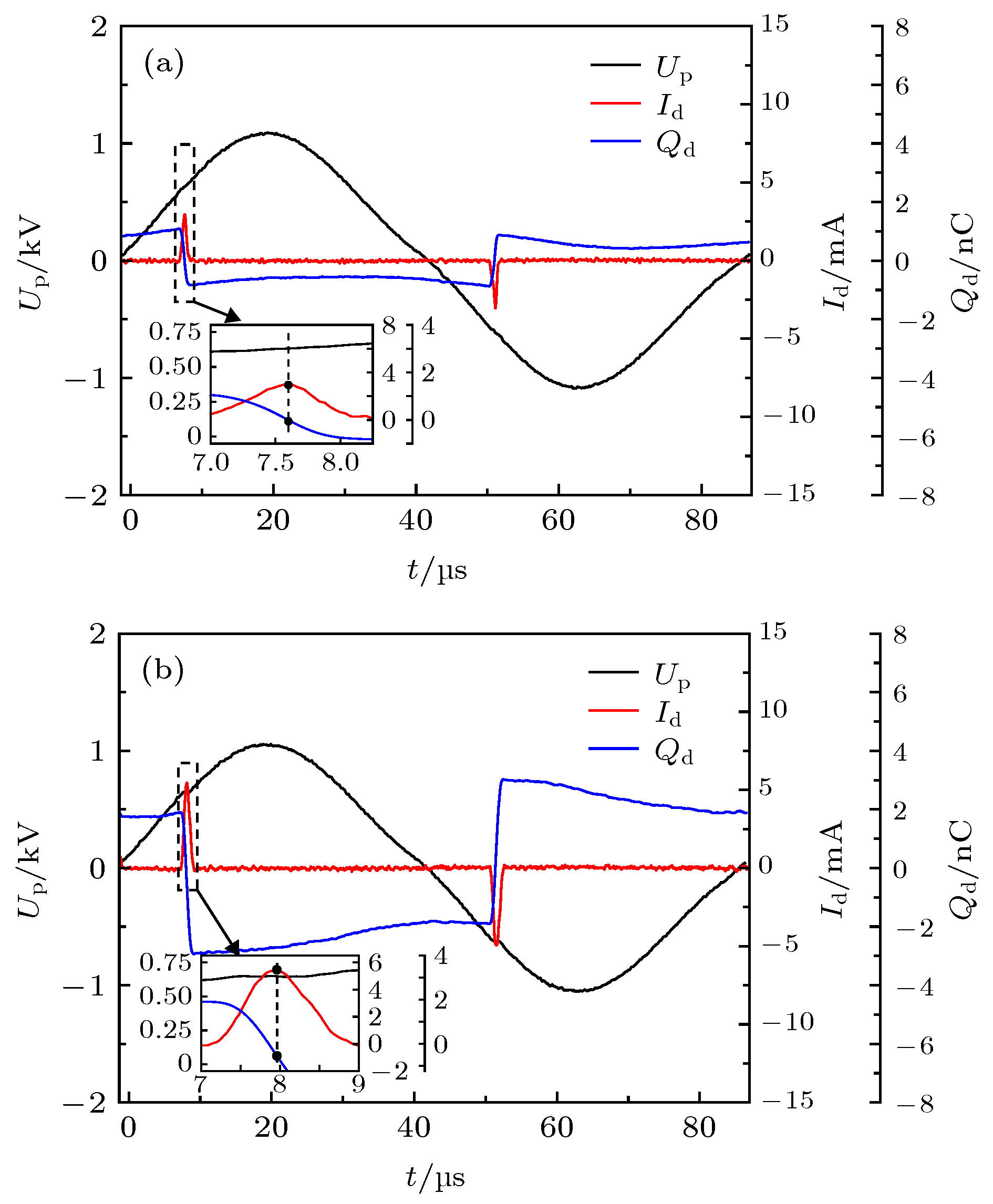
图 8 1 + 7两层多柱放电(2.22 kV)、1 + 6 + 12三层多柱放电(2.19 kV)外施电压、放电电流、放电转移电荷波形(a) 2.22 kV; (b) 2.19 kV. 内插图为电流脉冲时期各波形的局部放大图
Figure 8. Waves of applied voltage, discharge current and discharge transferred charge: (a) Two layers columnar discharge (2.22 kV); (b) three layers columnar discharge (2.19 kV). The inserted figure is a partial enlarged view of these waveforms during the current pulse period in both (a) and (b).
表 1 单柱放电(2.23 kV)、1 + 7两层多柱放电(2.22 kV)、1 + 6 + 12三层多柱放电(2.19 kV)的柱直径、柱间距
Table 1. Diameters and spacing of discharge columns in single-column discharge (2.23 kV), two layers columnar discharge (2.22 kV), and three layers columnar discharge (2.19 kV).
Ups = 2.23 kV Ups = 2.22 kV Ups = 2.19 kV n d1n/mm d1n/mm d2n/mm l12n/mm d1n/mm d2n/mm l12n/mm d3n/mm l23n/mm 1 2.21 3.10 3.59 4.33 3.21 3.42 4.21 3.69 4.03 2 — — 3.50 4.28 — 3.31 3.88 3.43 4.54 3 — — 3.29 4.29 — 3.36 4.25 3.65 3.83 4 — — 3.36 4.55 — 3.45 4.18 3.57 4.47 5 — — 3.37 4.25 — 3.58 4.26 3.59 3.83 6 — — 3.65 4.22 — 3.40 4.14 3.58 4.44 7 — — 3.45 4.26 — — — 3.59 3.85 8 — — — — — — — 3.83 4.38 9 — — — — — — — 3.81 4.01 10 — — — — — — — 3.42 4.27 11 — — — — — — — 3.41 4.05 12 — — — — — — — 3.69 4.30 AVE 2.21 3.10 3.45 4.31 3.21 3.42 4.15 3.61 4.17 D 0 0 1.69% 1.22% 0 0.85% 1.99% 1.94% 6.94% 表 2 1 + 7两层多柱放电(2.22 kV)、1 + 6 + 12三层多柱放电(2.19 kV)的放电柱受力分析参数
Table 2. Parameters used when calculating Lorentz force and Coulomb force under two layers columnar discharge (2.22 kV) and three layers columnar discharge (2.19 kV).
Ups/kV θ/(°) α/(°) r/mm l/mm h/mm 用于计算FQ 用于计算FI Qd/nC Q/nC Id/mA I/mA 2.22 51.43 64.29 3.74 4.31 3 0.12 0.015 2.95 0.37 2.19 60 60 4.16 4.16 3 0.31 0.016 5.40 0.28 表 3 1 + 7两层多柱放电(2.22 kV)、1 + 6 + 12三层多柱放电(2.19 kV)的柱间库仑力与磁场力
Table 3. Coulomb force and Lorentz force of discharge columns under two layers columnar discharge (2.22 kV) and three layers columnar discharge (2.19 kV).
Ups/kV FQ/10–7 N FI/10–14 N 2.22 4.01 7.01 2.19 QS QS1 QS2 QS QS1 QS2 5.35 4.82 2.25 4.69 4.22 1.97 -
[1] 王新新 2009 高电压技术 35 1
 Google Scholar
Wang X X 2009 High Volt. Eng. 35 1
 Google Scholar
[2] 郝艳捧, 关志成, 王黎明, 王新新, 李成榕 2005 高电压技术 31 42
 Google Scholar
Hao Y P, Guan Z C, Wang L M, Wang X X, Li C R 2005 High Volt. Eng. 31 42
 Google Scholar
[3] Ding H X, Zhu A M, Lu F G, Xu Y, Zhang J, Yang X F 2006 J. Phys. D: Appl. Phys. 39 3603
 Google Scholar
[4] Durme J V, Dewulf J, Leys C, Langenhove H V 2008 Appl. Catal. B: Environ. 78 324
 Google Scholar
[5] Kim H H 2004 Plasma Process Polym. 1 91
 Google Scholar
[6] Kogelschatz U 2002 IEEE Trans. Plasma Sci. 30 1400
 Google Scholar
[7] Golubovskii Y B, Maiorov V A, Behnke J, Behnke J F 2003 J. Phys. D: Appl. Phys. 36 39
 Google Scholar
[8] Luo H Y, Liang Z, Wang X X, Guan Z C, Wang L M 2010 J. Phys. D: Appl. Phys. 43 155201
 Google Scholar
[9] Astrov Y A, Logvin Y A 1997 Phys. Rev. Lett. 79 2983
 Google Scholar
[10] Dong L F, Shang J, He Y F, Bai Z G, Liu L, Fan W L 2012 Phys. Rev. E 85 066403
 Google Scholar
[11] 梁卓, 罗海云, 王新新, 关志成, 王黎明 2010 59 8739
 Google Scholar
Liang Z, Luo H Y, Wang X X, Guan Z C, Wang L M 2010 Acta Phys. Sin. 59 8739
 Google Scholar
[12] Mukaigawa S, Fujiwara K, Sato T, Odagiri R, Kudoh T, Yokota A, Oguni K, Takaki K 2016 Jpn. J. Appl. Phys. 55 07LB04
 Google Scholar
[13] Hao Y P, Han Y Y, Huang Z M, Yang L, Dai D, Li L C 2018 Phys. Plasmas 25 013516
 Google Scholar
[14] Radu I, Bartnikas R, Czeremuszkin G, Wertheimer M R 2003 IEEE Trans. Plasma Sci. 31 411
 Google Scholar
[15] Astrov Y A, Ammelt E, Purwins H-G 1997 Phys. Rev. Lett. 78 3129
 Google Scholar
[16] 董丽芳, 高瑞玲, 贺亚峰, 范伟丽, 李雪辰, 刘书华, 刘微粒 2007 56 1471
 Google Scholar
Dong L F, Gao R L, He Y F, Fan W L, Li X C, Liu S H, Liu W L 2007 Acta Phys. Sin. 56 1471
 Google Scholar
[17] Hao Y P, Zheng B, Liu Y G 2014 Phys. Plasmas 21 013503
 Google Scholar
[18] Müller I, Ammelt E, Purwins H-G 1999 Phys. Rev. Lett. 82 3428
 Google Scholar
[19] Hao Y P, Fang Q, Wan H R, Han Y Y, Yang L, Li L C 2019 Phys. Plasmas 26 073518
 Google Scholar
[20] Shirafuji T, Kitagawa T, Wakai T, Tachibana K 2003 Appl. Phys. Lett. 83 2309
 Google Scholar
[21] Bedanov V M, Peeters F M 1994 Phys. Rev. B 49 2667
 Google Scholar
[22] Boeuf J P, Bernecker B, Callegari T, Blanco S, Fournier R 2012 Appl. Phys. Lett. 100 244108
 Google Scholar
[23] 郝艳捧, 刘耀阁, 郑彬 2012 高电压技术 38 1025
 Google Scholar
Hao Y P, Liu Y G, Zheng B 2012 High Volt. Eng. 38 1025
 Google Scholar
[24] 郝艳捧, 阳林, 涂恩来, 陈建阳 2009 高电压技术 35 1879
 Google Scholar
Hao Y P, Yang L, Tu E L, Chen J Y 2009 High Volt. Eng. 35 1879
 Google Scholar
[25] Falkenstein Z, Coogan J J 1997 J. Phys. D: Appl. Phys. 30 817
 Google Scholar
Catalog
Metrics
- Abstract views: 9209
- PDF Downloads: 90
- Cited By: 0


 DownLoad:
