-
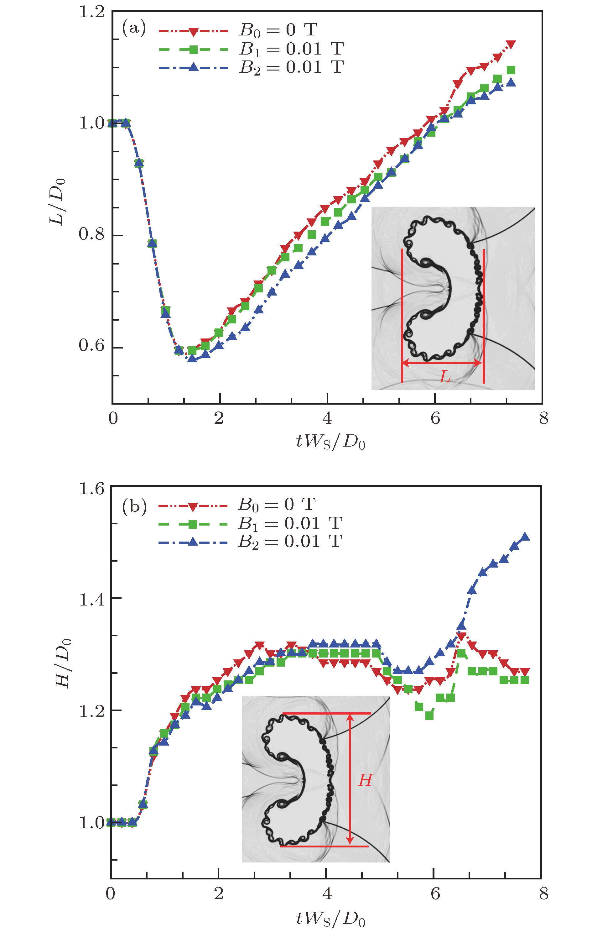
Based on magnetohydrodynamics(MHD), the evolution of the Richtmyer-Meshkov instability in different magnetic field configurations are studied. To ensure the zero magnetic divergence, an unsplit integration algorithm is adopted by combining corner transport upwind and constrained transport (CTU+CT) algorithm. The second order Godunov flux is obtained by using piecewise parabolic method(PPM) to construct conserved variables. The numerical results show that the evolution of complex wave patterns is not affected by magnetic fields, but the interface instability is compressed by magnetic field, especially in the case of transverse magnetic fields. Specifically, whether there exists magnetic field or not, irregular reflections occur outside the cylinder. Meanwhile, the central part of incident shock wave interacts with the density interface and generates the transmitted shock wave. Subsequently, the transmitted shock wave oscillates back and forth inside the cylinder, forming a transmission-reflection structure multiple times. Besides, in the absence of magnetic field, the density interface rolls up with a series of vortex sequences and an SF6 jet surrounded by vortex pairs appears. Then the SF6 jet passes through the downstream interface. In a longitudinal magnetic field, although density interface is smooth, a few vortex sequences still exist in the downstream interface and SF6 jet can still pass through downstream interface. However, in the case of transverse magnetic field, the interface is much smoother than in the other cases and the SF6 jet cannot pass through the downstream interface. The quantitative study also indicate that the increase of characteristic sizes is suppressed by the magnetic field. In addition, because of the influence of Richtmyer-Meshkov instability, magnetic lines are distorted near density interfaces. More distortions can be observed in the upstream interfaces, resulting in strong Lorentz forces in that area, which leads to the long distance between two vortex sheets distributed along two sides of the interface. In the downstream interfaces Lorentz forces are rather small, but the forces are even smaller in the longitudinal magnetic field, as a result vortex sheets interact with each other in that area. Furthermore, the dynamic mode decomposition(DMD) is primarily used in this paper and the results illustrate that even controlled by magnetic fields, vortex sequences can still exist, especially in the case of longitudinal magnetic field. For all cases, the first DMD modes all illustrate that a stable mode is the dominated feature of fluid field, and the following second to fourth mode show that the strength of vortex sequences decreases while their frequencies increase continually. Besides, for the same modes, the frequency of vortex sequences is reduced by magnetic fields, especially by the transverse magnetic field.
-
Keywords:
- Richtmyer-Meshkov instability /
- magnetohydrodynamic /
- dynamic mode decomposition /
- light bubble
[1] Richtmyer R D 1960 Commun. Pure Appl. Math. 13 297
 Google Scholar
[2] Meshkov E E 1969 Fluid Dyn. 4 101
[3] Brouillette M 2002 Annu. Rev. Fluid Mech. 34 445
 Google Scholar
[4] Haas J F, Sturtevant B 1987 J. Fluid Mech. 181 41
 Google Scholar
[5] Layes G, Jourdan G, Houas L 2003 Phys. Rev. Lett. 91 174502
 Google Scholar
[6] Layes G, Jourdan G, Houas L 2009 Phys. Fluids 21 074102
 Google Scholar
[7] Picone J M, Boris J P 1988 J. Fluid Mech. 189 23
 Google Scholar
[8] Zhai Z G, Wang M H, Si T, Luo X S 2014 J. Fluid Mech. 757 800
 Google Scholar
[9] Luo X S, Wang M H, Si T, Zhai Z G 2015 J. Fluid Mech. 773 366
 Google Scholar
[10] 沙莎, 陈志华, 张庆兵 2015 64 015201
 Google Scholar
Sha S, Chen Z H, Zhang Q B 2015 Acta Phys. Sin. 64 015201
 Google Scholar
[11] 沙莎, 陈志华, 薛大文 2013 62 144701
 Google Scholar
Sha S, Chen Z H, Xue D W 2013 Acta Phys. Sin. 62 144701
 Google Scholar
[12] Ding J C, Si T, Chen M J, Zhai Z G, Lu X Y, Luo X S 2017 J. Fluid Mech. 828 289
 Google Scholar
[13] Samtaney R 2003 Phys. Fluids 15 L53
 Google Scholar
[14] Wheatley V, Pullin D I, Samtaney R 2005 J. Fluid Mech. 522 179
 Google Scholar
[15] Wheatley V, Pullin D I, Samtaney R 2005 Phys. Rev. Lett. 95 125002
 Google Scholar
[16] Cao J T, Wu Z W, Ren H J, Dong L 2008 Phys. Plasmas 15 445
[17] 董国丹, 张焕好, 林震亚, 秦建华, 陈志华, 郭则庆, 沙莎 2018 67 204701
 Google Scholar
Dong G D, Zhang H H, Lin Z Y, Qin J H, Chen Z H, Guo Z Q, Sha S 2018 Acta Phys. Sin. 67 204701
 Google Scholar
[18] Sano T, Nishihara K, Matsuoka C, Inoue T 2012 Astrophys. J 758 126
 Google Scholar
[19] Sano T, Inoue T, Nishihara K 2013 Phys. Rev. Lett. 111 20500
[20] Schmid P J 2010 J. Fluid Mech. 656 5
 Google Scholar
[21] Schmid P J 2011 Exp. Fluids 50 1123
 Google Scholar
[22] Schmid P J, Li L, Juniper M P, Pust O 2011 Theor. Comp. Fluid Dyn. 25 249
 Google Scholar
[23] Mezić I 2013 Annu. Rev. Fluid Mech. 45 357
 Google Scholar
[24] Rowley C W, Mezić I, Bagheri S, Schlatter I, Henningson D S 2009 J. Fluid Mech. 641 115
 Google Scholar
[25] Colella P, Woodward P R 1984 J. Comput. Phys. 54 174
 Google Scholar
[26] Gardiner T A, Stone J M 2008 J. Comput. Phys. 227 4123
 Google Scholar
[27] Londrillo P, Zanna L D 2003 J. Comput. Phys. 195 17
[28] Lin Z Y, Zhang H H, Chen Z H, Liu Y, Hong Y J 2017 Int. J. Comput. Fluid D 31 21
 Google Scholar
[29] Kutz J N, Brunton S L, Brunton B W, Proctor J L 2016 Dynamic Mode Decomposition: Data-driven Modeling of Complex Systems (SIAM, Philadelphia, PA)
6−9 [30] Tu J H, Rowley C W, Luchtenburg D M, Brunton, S L, Kutz J N 2014 J. Comput. Dynam. 1 391
 Google Scholar
-
图 2 网格无关性验证 (a) 500 × 200; (b) 1000 × 400; (c) 2000 × 800; (d) 密度界面网格收敛性验证. ρ/ρ1为沿气柱对称轴密度比, 其中ρ是流体密度, ρ1是SF6气体密度; CRS: 弧形反射激波; LI: 气柱左边界; TS1: 透射激波; RI: 气柱右边界
Figure 2. Grid convergence validation: (a) 500 × 200; (b) 1000 × 400; (c) 2000 × 800; (d) convergence of density profile. ρ/ρ1 is the ratio of fluid density to SF6 density. CRS: curved reflected shock; LI: cylinder’s left interface; TS1: transmitted shock; RI: cylinder’s right interface.
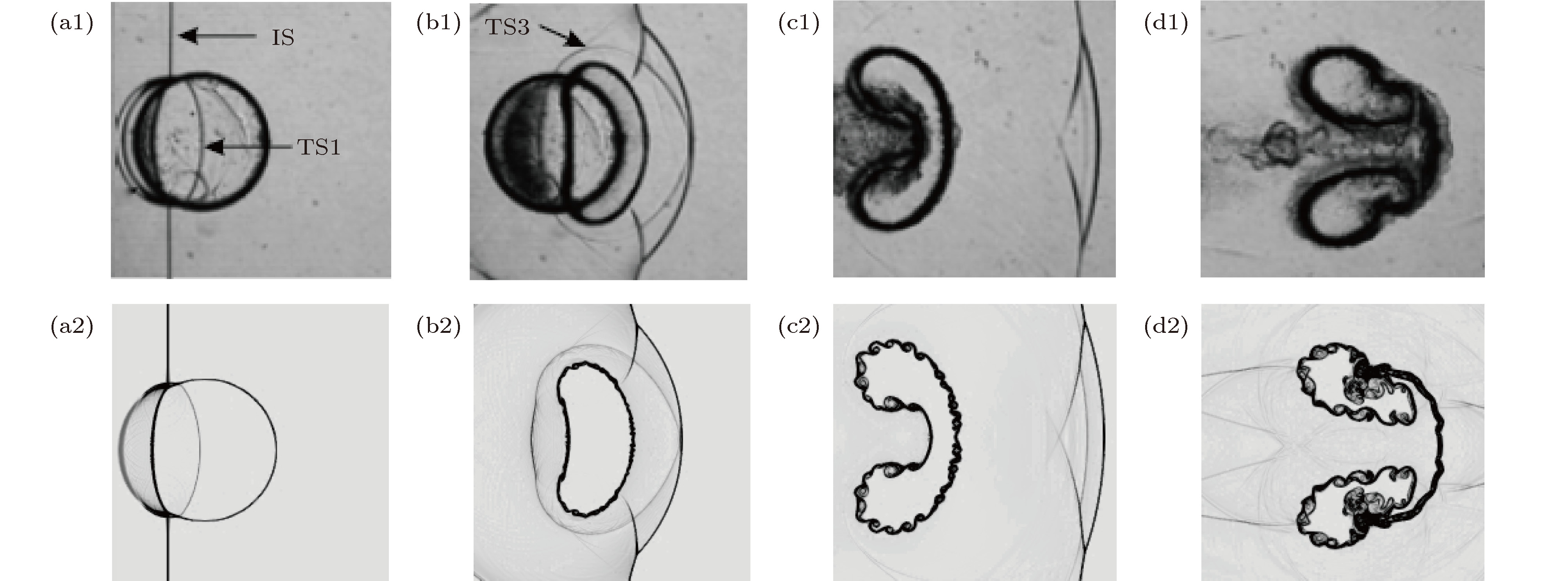
图 3 激波与N2气柱相互作用过程实验[12](上)与本文数值(下)密度纹影图的对比(IS: 入射激波; TS1: 透射激波; TS3: 三次透射激波) (a1) t = 120 μs; (a2) t = 120 μs; (b1)t = 280 μs; (b2) t = 280 μs; (c1) t = 580 μs; (c2) t = 580 μs; (d1) t = 1100 μs; (d2) t = 1100 μs
Figure 3. The comparison of experimental and numerical density schlieren images during the interaction between the incident shock wave and the N2 cylinder (IS: incident shock; TS1: transmitted shock; TS3: third transmitted shock): (a1) t = 120 μs; (a2) t = 120 μs; (b1)t = 280 μs; (b2) t = 280 μs; (c1) t = 580 μs; (c2) t = 580 μs; (d1) t = 1100 μs; (d2) t = 1100 μs.
图 4 无磁场时激波与N2气柱作用过程中的密度纹影图(IS: 入射激波; TS1: 透射激波; CRS: 弧形反射激波; RRW: 反射稀疏波; FPS: 自由前导激波; TS2: 二次透射激波; RS1:反射激波; MS: 马赫杆; TP: 三波点; FP: 聚焦点; S1: 激波1; RAS: 折射激波; TS3: 三次透射激波; RS2: 二次反射激波; TS4: 四次透射激波; URS:上壁面反射激波; LRS:下壁面反射激波; BRS: 尾壁反射激波; SL: 滑移线) (a) t = 160 μs; (b) t = 180 μs; (c) t = 210 μs; (d) t = 240 μs; (e) t = 290 μs; (f) t = 330 μs; (g) t = 430 μs; (h) t = 700 μs; (i) t = 1200 μs; (j) t = 1650 μs
Figure 4. The density schlieren image sequences during the interaction between the incident shock and N2 cylinder in the absence of magnetic fields(IS: incident shock; TS1: transmitted shock; CRS: curved reflected shock; RRW: reflected rarefaction shock; FPS: free precursor shock; TS2: second transmitted shock; RS1: reflected shock; MS: Mach stem; TP: triple point; FP: focus point; S1: shock 1; RAS: refracted shock; TS3: third transmitted shock; RS2: second reflected shock; TS4: fourth transmitted shock; URS: upper wall reflected shock; LRS: lower wall reflected shock; BRS: back wall reflected shock; SL: slip line): (a) t = 160 μs; (b) t = 180 μs; (c) t = 210 μs; (d) t = 240 μs; (e) t = 290 μs; (f) t = 330 μs; (g) t = 430 μs; (h) t = 700 μs; (i) t = 1200 μs; (j) t = 1650 μs.
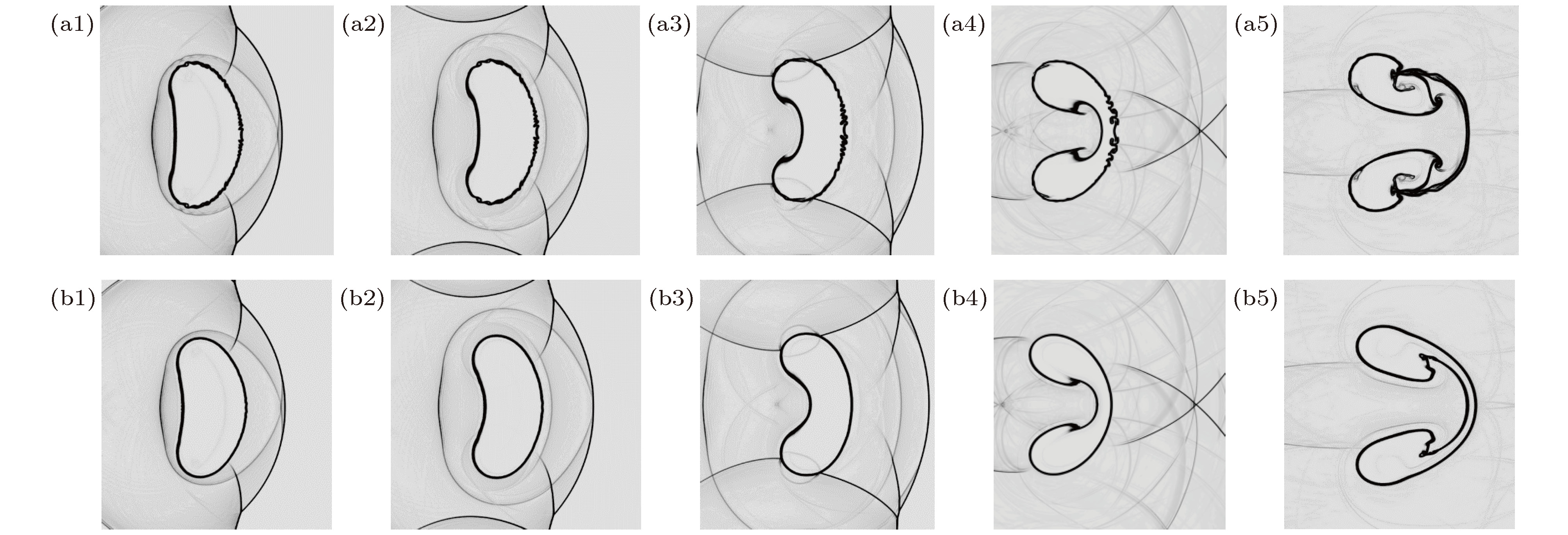
图 5 纵向B1(上)和横向B2(下)磁场构型下, 激波与N2气柱相互作用过程的密度纹影图 (a1)t = 290 μs; (b1) t = 290 μs; (a2) t = 330 μs; (b2) t = 330 μs; (a3) t = 430 μs;(b3) t = 430 μs; (a4)t = 700 μs; (b4) t = 700 μs; (a5)t = 1200 μs; (b5) t = 1200 μs
Figure 5. The density schlieren image sequences during the interaction between the incident shock and N2 cylinder in the presence of the longitudinal B1 (upper) and transverse B2 (lower) magnetic fields: (a1)t = 290 μs; (b1) t = 290 μs; (a2) t = 330 μs; (b2) t = 330 μs; (a3) t = 430 μs; (b3) t = 430 μs; (a4)t = 700 μs; (b4) t = 700 μs; (a5)t = 1200 μs; (b5) t = 1200 μs.
图 6 t = 200 μs时, 纵向和横向磁场构型的结果 (a1)纵向磁场的磁力线(蓝色)与流线(红色)图, 其中背景为密度纹影图; (b1)横向磁场的磁力线(蓝色)与流线(红色)图, 其中背景为密度纹影图; (a2)纵向磁场x方向的洛伦兹力Fx分布云图; (b2)横向磁场x方向的洛伦兹力Fx分布云图; (a3)纵向磁场y方向洛伦兹力Fy分布云图; (b3)横向磁场y方向洛伦兹力Fy分布云图; (a4)纵向磁场沿线段A(图(a2)中黑色线段所示)x和y方向洛伦兹力定量图; (b4)横向磁场沿线段A(图(a2)中黑色线段所示)x和y方向洛伦兹力定量图. 其中线段A两端点分别为 (0, 0.01), (0.025, 0.01)
Figure 6. Results from longitudinal and transverse magnetic fields at t = 200 μs: (a1)longitudinal magnetic field lines (blue) and streamlines (red), the background are density schlieren images;(b1) transverse magnetic field lines (blue) and streamlines (red), the background are density schlieren images;(a2)Lorentz forces distribution of longitudinal magnetic field in x direction, Fx;(b2)Lorentz forces distribution of transverse magnetic field in x direction, Fx;(a3)Lorentz forces distribution of longitudinal magnetic field in y direction, Fy;(b3)Lorentz forces distribution of transverse magnetic field in y direction, Fy;(a4)the specific Lorentz forces distribution of longitudinal magnetic field along a horizontal line A, indicated by the black solid line in Fig. 6 (a2), and the two end points are (0, 0.01), (0.025, 0.01);(b4)the specific Lorentz forces distribution of transverse magnetic field along a horizontal line A, indicated by the black solid line in Fig. 6 (a2), and the two end points are (0, 0.01), (0.025, 0.01).
图 7 t = 600 μs时界面涡量分布图 (a)无磁场, B = 0 T; (b)纵向磁场, B1 = 0.01 T; (c)横向磁场, B2 = 0.01 T
Figure 7. The vorticity distribution in the vicinity of the density interface at t = 600 μs: (a) in the absence of magnetic fields, B = 0 T; (b) in the presence of longitudinal magnetic fields, B1 = 0.01 T; (c)in the presence of transverse magnetic fields, B2 = 0.01 T.
图 11 t = 290 μs时原始涡量和DMD重构涡量图 (a1)无磁场 B0 = 0 T, 原始涡量图; (a2)纵向磁场 B1 = 0.01 T, 原始涡量图; (a3)横向磁场 B2 = 0.01 T, 原始涡量图; (b1)无磁场 B0 = 0.0 T, DMD重构涡量图; (b2)纵向磁场 B1 = 0.01 T, DMD重构涡量图; (b3)横向磁场 B2 = 0.01 T, DMD重构涡量图
Figure 11. The distribution of original vorticities and DMD reconstructed vorticities at t = 290 μs: (a1)Original vorticities, B0 = 0 T, hydro cases; (a2) original vorticities, B1 = 0.01 T, longitudinal magnetic fields; (a3) original vorticities, B2 = 0.01 T, transverse magnetic fields; (b1) DMD reconstructed vorticities, B0 = 0 T, hydro cases; (b2) DMD reconstructed vorticities, B1 = 0.01 T, longitudinal magnetic fields; (b3) DMD reconstructed vorticities, B2 = 0.01 T, transverse magnetic fields.
图 12 无磁场、纵向和横向磁场下DMD的四个不同特征值对应的模态图 (a1)无磁场, λ1 = (0.9764, 0.0000); (a2)无磁场, λ2 = (0.9061, 0.2856); (a3)无磁场, λ3 = (0.8236, 0.5226); (a4)无磁场, λ4 = (0.3514, 0.8943); (b1)纵向磁场, λ1 = (0.9816, 0.0000); (b2)纵向磁场, λ2 = (0.9423,0.1925); (b3)纵向磁场, λ3 = (0.8212, 0.5150); (b4)纵向磁场, λ4 = (0.3929, 0.8828); (c1)横向磁场, λ1 = (0.9648, 0.0000); (c2)横向磁场, λ2 = (0.9601,0.1703); (c3)横向磁场, λ3 = (0.8314, 0.4774); (c4)横向磁场, λ4 = (0.3718, 0.8279)
Figure 12. DMD modes with respect to four different eigenvalues in hydro, longitudinal and transverse magnetic fields: (a1) In hydro field, λ1 = (0.9764, 0.0000); (a2) in hydro field, λ2 = (0.9061, 0.2856); (a3) in hydro field, λ3 = (0.8236, 0.5226); (a4) in hydro field λ4 = (0.3514, 0.8943); (b1) in longitudinal magnetic field, λ1 = (0.9816, 0.0000); (b2) in longitudinal magnetic field, λ2 = (0.9423,0.1925); (b3) in longitudinal magnetic field, λ3 = (0.8212, 0.5150); (b4) in longitudinal magnetic field, λ4 = (0.3929, 0.8828); (c1) in transverse magnetic field, λ1 = (0.9648, 0.0000); (c2) in transverse magnetic field, λ2 = (0.9601, 0.1703); (c3) in transverse magnetic field, λ3 = (0.8314, 0.4774); (c4) in transverse magnetic field, λ4 = (0.3718, 0.8279).
表 1 气体参数表
Table 1. Gas parameters
气体 密度ρ/(kg·m–3) 比热比γ 当地音速a/(m·s–1) 相对分子质量/(g·mol–1) SF6 6.06 1. 09 134.89 146.00 97%N2+3% SF6 1.31 1.36 324.71 31.54 -
[1] Richtmyer R D 1960 Commun. Pure Appl. Math. 13 297
 Google Scholar
[2] Meshkov E E 1969 Fluid Dyn. 4 101
[3] Brouillette M 2002 Annu. Rev. Fluid Mech. 34 445
 Google Scholar
[4] Haas J F, Sturtevant B 1987 J. Fluid Mech. 181 41
 Google Scholar
[5] Layes G, Jourdan G, Houas L 2003 Phys. Rev. Lett. 91 174502
 Google Scholar
[6] Layes G, Jourdan G, Houas L 2009 Phys. Fluids 21 074102
 Google Scholar
[7] Picone J M, Boris J P 1988 J. Fluid Mech. 189 23
 Google Scholar
[8] Zhai Z G, Wang M H, Si T, Luo X S 2014 J. Fluid Mech. 757 800
 Google Scholar
[9] Luo X S, Wang M H, Si T, Zhai Z G 2015 J. Fluid Mech. 773 366
 Google Scholar
[10] 沙莎, 陈志华, 张庆兵 2015 64 015201
 Google Scholar
Sha S, Chen Z H, Zhang Q B 2015 Acta Phys. Sin. 64 015201
 Google Scholar
[11] 沙莎, 陈志华, 薛大文 2013 62 144701
 Google Scholar
Sha S, Chen Z H, Xue D W 2013 Acta Phys. Sin. 62 144701
 Google Scholar
[12] Ding J C, Si T, Chen M J, Zhai Z G, Lu X Y, Luo X S 2017 J. Fluid Mech. 828 289
 Google Scholar
[13] Samtaney R 2003 Phys. Fluids 15 L53
 Google Scholar
[14] Wheatley V, Pullin D I, Samtaney R 2005 J. Fluid Mech. 522 179
 Google Scholar
[15] Wheatley V, Pullin D I, Samtaney R 2005 Phys. Rev. Lett. 95 125002
 Google Scholar
[16] Cao J T, Wu Z W, Ren H J, Dong L 2008 Phys. Plasmas 15 445
[17] 董国丹, 张焕好, 林震亚, 秦建华, 陈志华, 郭则庆, 沙莎 2018 67 204701
 Google Scholar
Dong G D, Zhang H H, Lin Z Y, Qin J H, Chen Z H, Guo Z Q, Sha S 2018 Acta Phys. Sin. 67 204701
 Google Scholar
[18] Sano T, Nishihara K, Matsuoka C, Inoue T 2012 Astrophys. J 758 126
 Google Scholar
[19] Sano T, Inoue T, Nishihara K 2013 Phys. Rev. Lett. 111 20500
[20] Schmid P J 2010 J. Fluid Mech. 656 5
 Google Scholar
[21] Schmid P J 2011 Exp. Fluids 50 1123
 Google Scholar
[22] Schmid P J, Li L, Juniper M P, Pust O 2011 Theor. Comp. Fluid Dyn. 25 249
 Google Scholar
[23] Mezić I 2013 Annu. Rev. Fluid Mech. 45 357
 Google Scholar
[24] Rowley C W, Mezić I, Bagheri S, Schlatter I, Henningson D S 2009 J. Fluid Mech. 641 115
 Google Scholar
[25] Colella P, Woodward P R 1984 J. Comput. Phys. 54 174
 Google Scholar
[26] Gardiner T A, Stone J M 2008 J. Comput. Phys. 227 4123
 Google Scholar
[27] Londrillo P, Zanna L D 2003 J. Comput. Phys. 195 17
[28] Lin Z Y, Zhang H H, Chen Z H, Liu Y, Hong Y J 2017 Int. J. Comput. Fluid D 31 21
 Google Scholar
[29] Kutz J N, Brunton S L, Brunton B W, Proctor J L 2016 Dynamic Mode Decomposition: Data-driven Modeling of Complex Systems (SIAM, Philadelphia, PA)
6−9 [30] Tu J H, Rowley C W, Luchtenburg D M, Brunton, S L, Kutz J N 2014 J. Comput. Dynam. 1 391
 Google Scholar
Catalog
Metrics
- Abstract views: 10681
- PDF Downloads: 64
- Cited By: 0


 DownLoad:


