-
采用格子Boltzmann方法模拟上下壁面驱动的二维梯形空腔流, 并使用GPU-CUDA程序进行加速计算. 主要采用本征正交分解方法, 分析了4种壁面驱动条件的流场模态, 并探究了雷诺数和驱动速度方向对流场形态的影响. 结果表明: 1)当上壁面单驱动(T1a)时, 若雷诺数为1000—8000, 流场处于稳态流动; 雷诺数为8500时, 流场处于周期性非稳态流动; 雷诺数大于10000时, 流场处于非周期非稳态流动. 2)当下壁面单驱动(T1b)时, 若雷诺数在1000—8000之间, 流场处于稳态流动; 雷诺数增大至11500时, 流场处于周期性非稳态流动; 雷诺数大于12500时, 流场进入非周期非稳态流动. 3)当上下壁面同方向同速度双驱动(T2a)时, 若雷诺数在1000—10000区间, 流场均为稳态流动; 雷诺数为12500—15000时, 流场处于周期性非稳态流动; 当雷诺数大于20000时, 流场为非周期非稳态流动. 4)当上下壁面反方向同速度双驱动(T2b)时, 若雷诺数在1000—5000之间, 流场处于稳态流动; 雷诺数为6000时, 流场处于周期性非稳态流动; 雷诺数大于8000时, 流场为非周期非稳态流动.
-
关键词:
- 格子Boltzmann方法 /
- 梯形空腔 /
- 双壁面驱动 /
- GPU-CUDA计算
In this study, we utilize the lattice Boltzmann method to investigate the flow behavior in a two-dimensional trapezoidal cavity, which is driven by both sides on the upper wall and lower wall. Our calculations are accelerated through GPU-CUDA software. We conduct an analysis of the flow field mode by using proper orthogonal decomposition. The effects of various parameters, such as Reynolds number (Re) and driving direction, on the flow characteristics are examined through numerical simulations. The results are shown below. 1) For the upper wall drive (T1a), the flow field remains stable, when the Re value varies from 1000 to 8000. However, when Re = 8500, the flow field becomes periodic but unstable. The velocity phase diagram at the monitoring point is a smooth circle, and the energy values of the first two modes dominate the energy of the whole field. Once Re exceeds 10000, the velocity phase diagram turns irregular and the flow field becomes aperiodic and unsteady. 2) For the lower wall drive (T1b), the flow is stable when Re value is in a range of 1000-8000, and it becomes periodic and unsteady when Re = 11500. The energy values of the first three modes appear relatively large. When Re is greater than 12500, the flow field becomes aperiodic and unsteady. At this time, the phase diagram exhibits a smooth circle, with the energy values of the first two modes almost entirely dominating the entire energy. 3) For the case of upper wall and lower wall moving in the same direction at the same speed (T2a), the flow field remains stable when Re changes from 1000 to 10000. When Re varies from 12500 to 15000, the flow becomes periodic and unstable. The velocity phase diagram is still a smooth circle, with the first two modes still occupying a large portion of the energy. Once Re exceeds 20000, the energy proportions of the first three modes significantly decrease, and the flow becomes aperiodic and unsteady. 4) For the case in which the upper wall and lower wall are driven in opposite directions at the same velocity (T2b), the flow field remains stable when Re changes from 1000 to 5000. When Re = 6000, the energy of the first mode accounts for 86%, and the flow field becomes periodic but unstable. When Re exceeds 8000, the energy proportions of the first three modes decrease significantly, and the flow field becomes aperiodic and unsteady.-
Keywords:
- lattice Boltzmann method /
- trapezoidal cavity /
- two-sided driven /
- GPU-CUDA computing
[1] Peng Y F, Shiau Y H, Hwang R R 2003 Comput. Fluids 32 337
 Google Scholar
[2] Isaev S A, Baranov P A, Sudakov A G, et al. 2008 Thermophys. Aeromech. 15 463
 Google Scholar
[3] Balachandar S, Eaton J K 2010 Annu. Rev. Fluid Mech. 42 111
 Google Scholar
[4] Kuhlmann H C, Romanò F 2019 The Lid-Driven Cavity (Austria: Springer International Publishing) p233
[5] Nonino C, Del Giudice S 1988 Int. J. Numer. Methods Eng. 25 313
 Google Scholar
[6] Alleborn N, Raszillier H, Durst F 1999 Int. J. Heat Mass Tran. 42 833
 Google Scholar
[7] Talebi F, Mahmoudi A H, Shahi M 2010 Int. Commun. Heat Mass 37 79
 Google Scholar
[8] Chowdhury M, Kumar B V R 2023 J. Nonnewton. Fluid Mech. 312 104975
 Google Scholar
[9] Ribbens C J, Watson L T, Wang C Y 1994 J. Comput. Phys. 112 173
 Google Scholar
[10] McQuain W D, Ribbens C J, Wang C Y, et al. 1994 Comput. Fluids 23 613
 Google Scholar
[11] Ismael M A, Chamkha A J 2015 Numer. Heat Transfer, Part A 68 312
 Google Scholar
[12] Mebarek-Oudina F, Laouira H, Hussein A K, et al. 2022 Mathematics 10 929
 Google Scholar
[13] Mondal P, Mahapatra T R 2021 Int. J. Mech. Sci. 208 106665
 Google Scholar
[14] Kareem A K, Mohammed H A, Hussein A K, et al. 2016 Int. Commun. Heat Mass 77 195
 Google Scholar
[15] Rashad A M, Sivasankaran S, Mansour M A, et al. 2017 Numer. Heat Transfer, Part A 71 1223
 Google Scholar
[16] Darr J H, Vanka S P 1991 Phys. Fluids 3 385
 Google Scholar
[17] Paramane S B, Sharma A 2008 Numer. Heat Transfer, Part B 54 84
 Google Scholar
[18] 张恒, 任峰, 胡海豹 2021 70 184703
 Google Scholar
Zhang H, Ren F, Hu H B 2021 Acta Phys. Sin. 70 184703
 Google Scholar
[19] Yang F, Shi X, Guo X, et al. 2012 Energy Procedia 16 639
 Google Scholar
[20] Nagendra K, Lakshmisha K N 2009 Int. J. Numer. Methods Heat Fluid Flow 19 790
 Google Scholar
[21] Perumal D A, Dass A K 2011 Comput. Math. Appl. 61 3711
 Google Scholar
[22] Nemati H, Farhadi M, Sedighi K, et al. 2010 Int. Commun. Heat Mass 37 1528
 Google Scholar
[23] Guo X, Zhong C, Zhuo C, et al. 2014 Theor. Comput. Fluid Dyn. 28 215
 Google Scholar
[24] Patil D V, Lakshmisha K N, Rogg B 2006 Comput. Fluids 35 1116
 Google Scholar
[25] Hou S, Zou Q, Chen S, et al. 1995 J. Comput. Phys. 118 329
 Google Scholar
[26] Chai Z H, Shi B C, Zheng L 2006 Chin. Phys. 15 1855
 Google Scholar
[27] Yuana K A, Budiana E P 2019 IOP Conf. Ser.: Mater. Sci. Eng. 546 052088
 Google Scholar
[28] Perumal D A, Dass A K 2008 WIT Trans. Eng. Sci. 59 45
 Google Scholar
[29] Bo A N, Mellibovsky F, Bergada J M, et al. 2020 Appl. Math. Modell. 82 469
 Google Scholar
[30] Shahid H, Yaqoob I, Khan W A, et al. 2021 Int. Commun. Heat Mass 129 105658
 Google Scholar
[31] Perumal D A 2018 Therm. Sci. Eng. Prog. 6 48
 Google Scholar
[32] Guo Y, Bennacer R, Shen S, et al. 2010 Int. J. Numer. Methods Heat Fluid Flow 20 130
 Google Scholar
[33] Shahid H, Yaqoob I, Khan W A, et al. 2021 Int. Commun. Heat Mass 128 105552
 Google Scholar
[34] An B, Bergada J M, Mellibovsky F 2019 J. Fluid Mech. 875 476
 Google Scholar
[35] An B, Guo S, Bergadà J M 2023 Appl. Sci. 13 888
 Google Scholar
[36] Sidik N A C, Munir F A 2012 Arab. J. Sci. Eng. 37 1723
 Google Scholar
[37] Zhang T, Shi B, Chai Z 2010 Compu. Fluids 39 1977
 Google Scholar
[38] Qian Y H, D’Humières D, Lallemand P 1992 EPL 17 479
 Google Scholar
[39] Ziegler D P 1993 J. Stat. Phys. 71 1171
 Google Scholar
[40] Guo Z L, Zheng C G, Shi B C 2002 Chin. Phys. 11 366
 Google Scholar
[41] Guo Z L, Zheng C G, Shi B C 2002 Phys. Fluids 14 2007
 Google Scholar
-
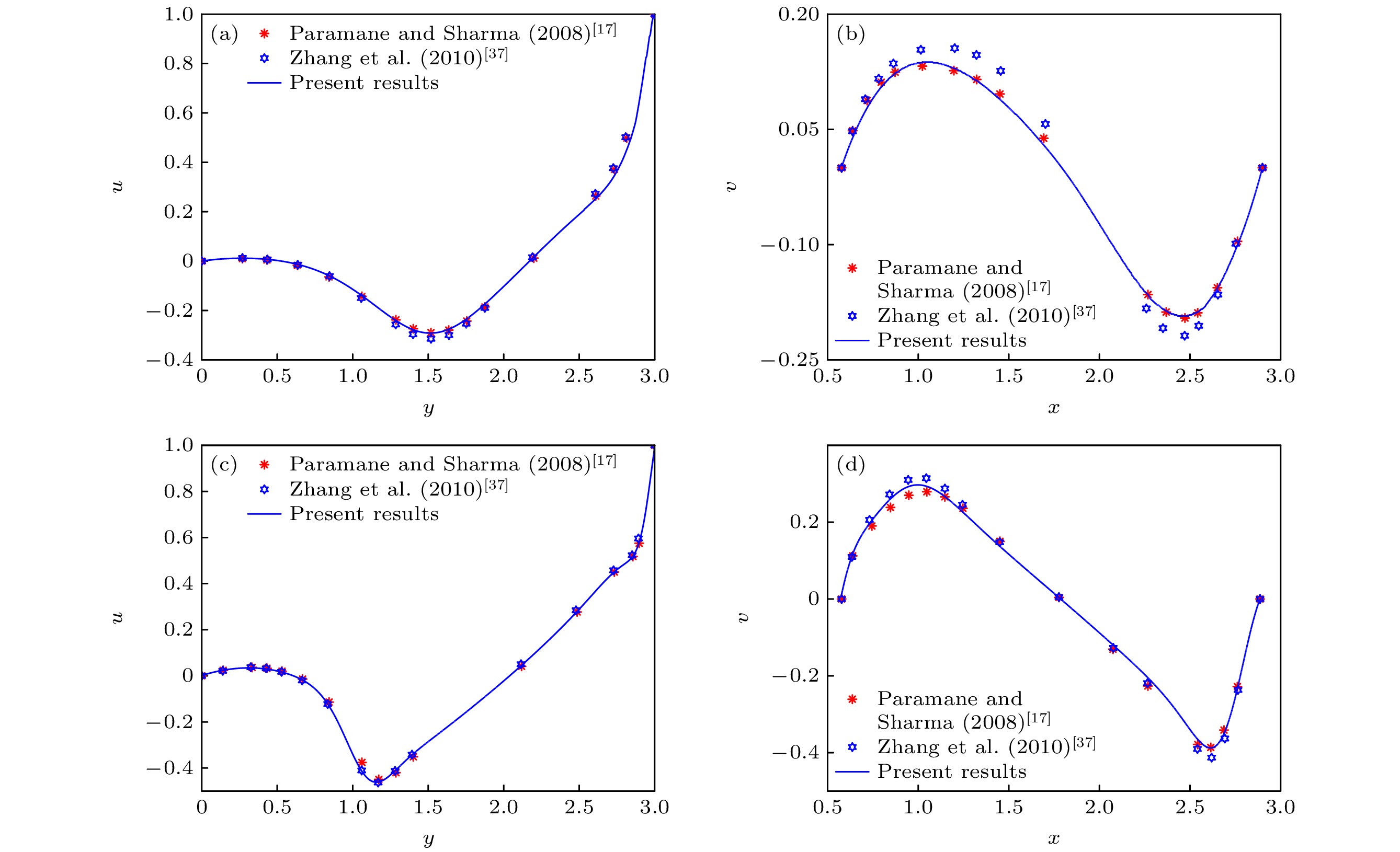
图 3 对比Re = 100和500时垂直和水平中线上的速度 (a), (c) 沿垂直中线的速度u和纵坐标y的关系图; (b), (d) 沿水平中线的速度v和横坐标x的关系图
Fig. 3. Comparison of the velocity profiles along the vertical and horizontal lines through cavity center at Re = 100, 500: (a) and (c) The y-component of velocity u profiles along the vertical line; (b) and (d) x-component of velocity v profiles along the horizontal line.
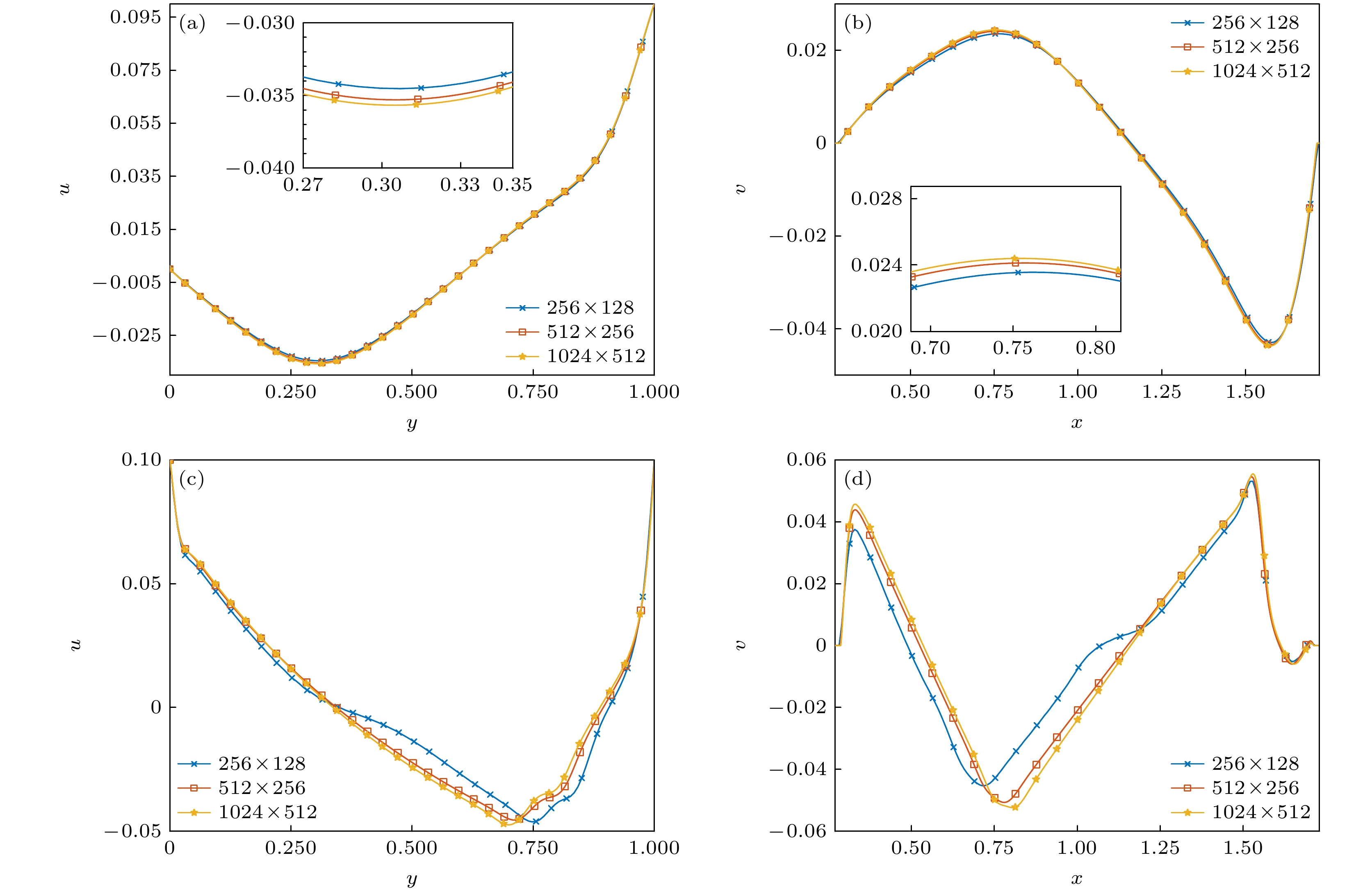
图 4 对比网格数为
$ 256\times128 $ ,$ 512\times256 $ ,$ 1024\times512 $ , Re = 500, 10000时垂直和水平中线上的速度.$ U_1=0.1 $ ,$ U_2=0 $ , Re = 500时(a)沿垂直中线的速度u和纵坐标y的关系图, (b)沿水平中线的速度v和横坐标x的关系图.$ U_1=0.1 $ ,$ U_2=0.1 $ , Re = 10000时(c) 沿垂直中线的速度u和纵坐标y的关系图, (d) 沿水平中线的速度v和横坐标x的关系图Fig. 4. Comparison of the velocity profiles along the vertical and horizontal lines at Re = 500, 10000 for
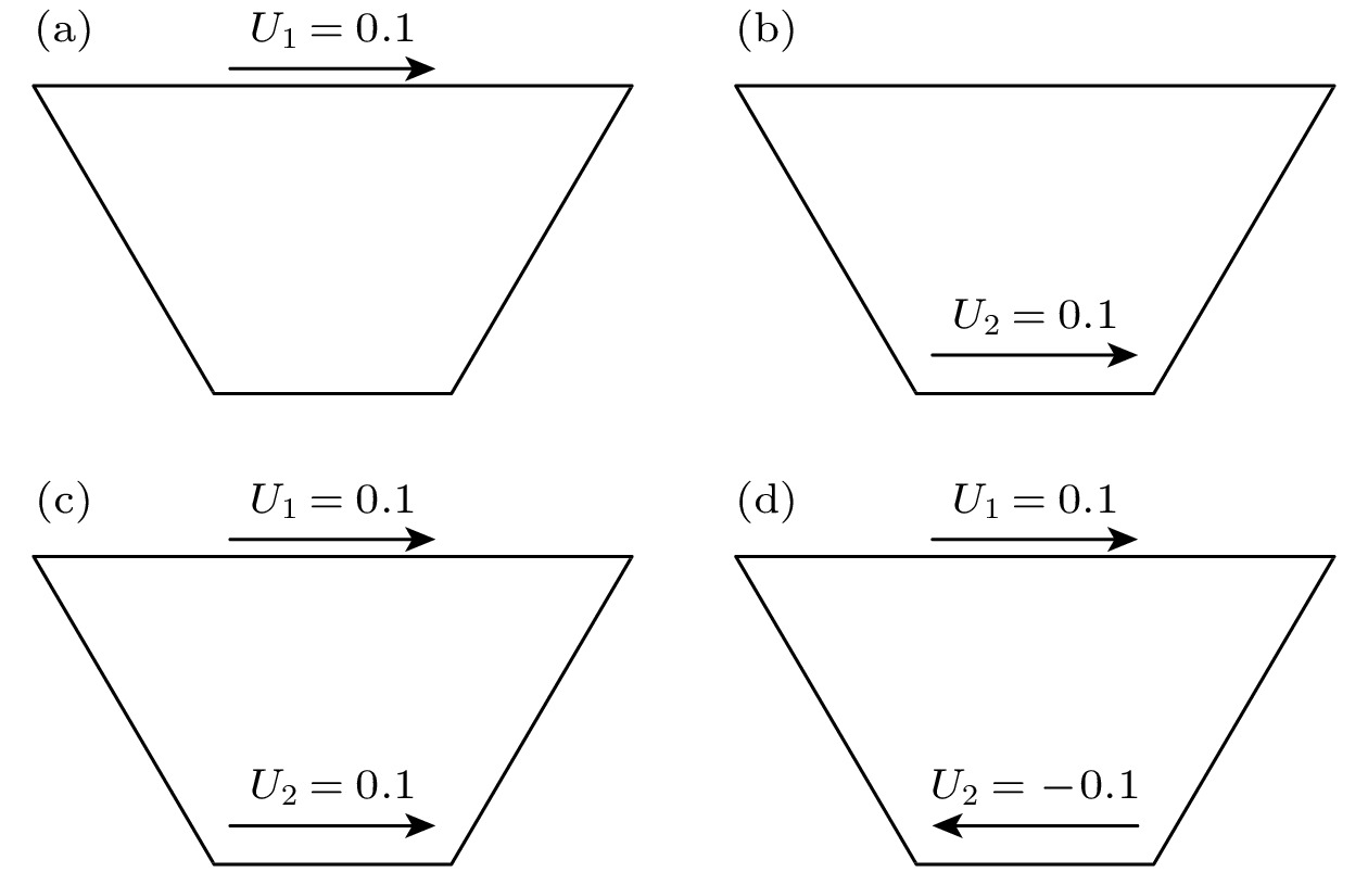
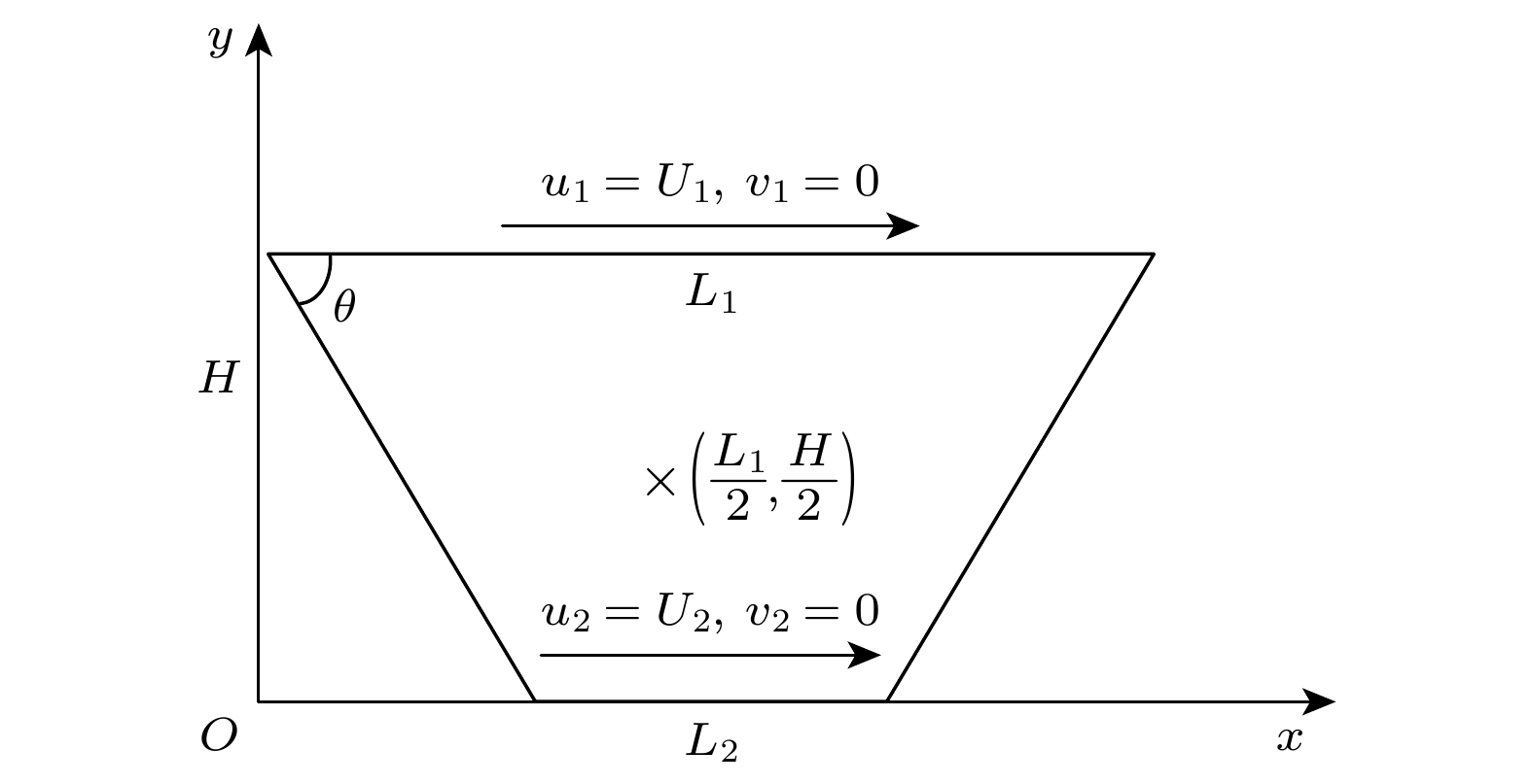
$ 256\times128 $ ,$ 512\times256 $ ,$ 1024\times512 $ . (a) The y-component of velocity u profiles along the vertical line, (b) x-component of velocity v profiles along the horizontal line at$ U_1=0.1 $ ,$ U_2=0 $ and Re = 500. (c) The y-component of velocity u profiles along the vertical line, (d) x-component of velocity v profiles along the horizontal line at$ U_1=0.1 $ ,$ U_2=0.1 $ and Re = 10000.图 5 4种不同壁面驱动速度下的梯形空腔示意图 (a) Case T1a, 上壁面向右单驱动; (b) Case T1b, 下壁面向右单驱动; (c) Case T2a, 上壁面和下壁面同时向右双驱动; (d) Case T2b, 上壁面向右驱动, 下壁面向左双驱动
Fig. 5. Trapezoidal cavity under four different velocity boundaries: (a) Case T1a, only the upper wall-driven; (b) Case T1b, only the lower wall-driven; (c) Case T2a, the upper and lower wall are driven at the same speed and in the same direction; (d) Case T2b, the upper and lower wall are driven at the same speed and in the opposite direction
图 8 Case T1a条件下, Re = 8500时呈现周期性非稳态流动 (a) 时间步
$ t=3000000 $ 时的流场图; (b) 监控点处速度相图; (c) 速度监控点处速度随时间的变化Fig. 8. Stream function contours are periodic and unsteady at Re = 8500 for Case T1a: (a) Stream function contours at time steps
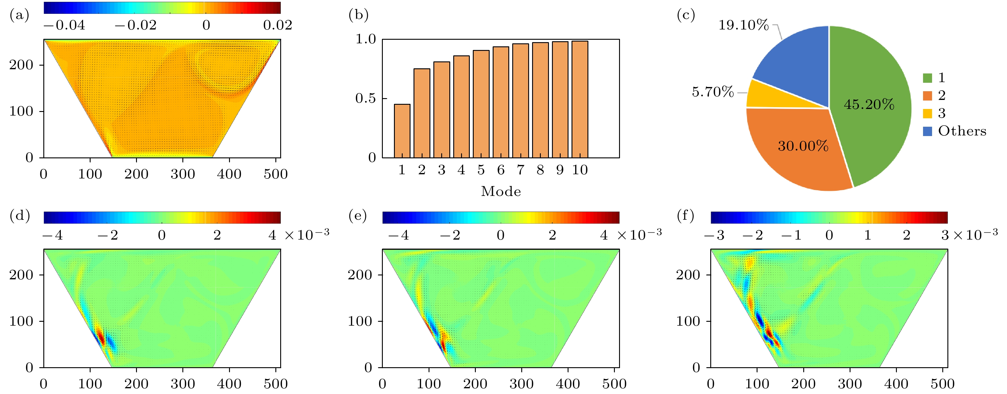
$ t=3000000 $ ; (b) velocity phase diagram at the velocity monitoring point; (c) velocity over time at the velocity monitoring point图 9 Case T1a条件下, Re = 8500时的各阶模态图 (a)速度平均场模态图; (b) 前n阶模态的能量占比; (c)各阶模态的能量占比; (d)—(f)一阶、二阶、三阶速度模态图
Fig. 9. Each order of mode for Case T1a when Re = 8500: (a) The mean field modal diagrams of velocity; (b) energy share of the first n order of mode for velocity; (c) energy share of each order of mode for velocity; (d)–(f) the first-order, second-order and third-order mode of velocity
图 10 Case T1a条件下, Re = 10000时呈现非周期非稳态流动 (a)时间步
$ t=5000000 $ 时的流场图; (b)监控点处速度相图; (c)速度监控点处速度随时间的变化Fig. 10. Stream function contours are non-periodic and unsteady at Re = 10000 for Case T1a: (a) Stream function contours at time steps
$ t=5000000 $ ; (b) velocity phase diagrams at the velocity monitoring point; (c) velocity over time at the velocity monitoring point图 11 Case T1a条件下, Re = 12500时呈现非周期非稳态流动 (a)时间步
$ t=5000000 $ 时的流场图; (b)监控点处速度相图; (c)监控点处速度随时间的变化Fig. 11. Stream function contours are non-periodic and unsteady at Re = 12500 for Case T1a: (a) Stream function contours at time steps
$ t=5000000 $ ; (b) velocity phase diagram at the velocity monitoring point; (c) velocity over time at the velocity monitoring point图 14 Case T1b条件下, Re = 11500时呈现周期性非稳态流动 (a)时间步
$ t=5000000 $ 时的流场图; (b)监控点处速度相图; (c)监控点处速度随时间变化图Fig. 14. (a) Stream function contours are periodic and unsteady at Re = 11500 for Case T1b: (a) Stream function contours at time steps
$ t=5000000 $ ; (b) velocity phase diagram at the velocity monitoring point; (c) velocity over time at the velocity monitoring point图 15 Case T1b条件下, Re = 11500时的各阶模态图 (a)速度平均场模态图; (b)前n阶模态的能量占比; (c)各阶模态的能量占比; (d)—(f)一阶、二阶、三阶速度模态图
Fig. 15. Each order of mode for Case T1b when Re = 11500: (a) The mean field modal diagrams of velocity; (b) energy share of the first n order of mode for velocity; (c) energy share of each order of mode for velocity; (d)–(f) the first-order, second-order and third-order mode of velocity
图 16 Case T1b条件下, Re = 12500时呈非周期非稳态流动 (a)时间步
$ t=6000000 $ 时的流场图; (b)监控点处速度相图; (c)速度监控点处速度随时间的变化Fig. 16. Stream function contours are non-periodic and unsteady at Re = 12500 for Case T1b: (a) Stream function contours at time steps
$ t=6000000 $ ; (b) velocity phase diagram at the velocity monitoring point; (c) velocity over time at the velocity monitoring point图 17 Case T1b条件下, Re = 15000时呈非周期非稳态流动 (a)时间步
$ t=6000000 $ 时的流场图; (b)监控点处速度相图; (c)速度监控点处速度随时间的变化Fig. 17. Stream function contours are non-periodic and unsteady at Re = 15000 for Case T1b: (a) Stream function contours at time steps
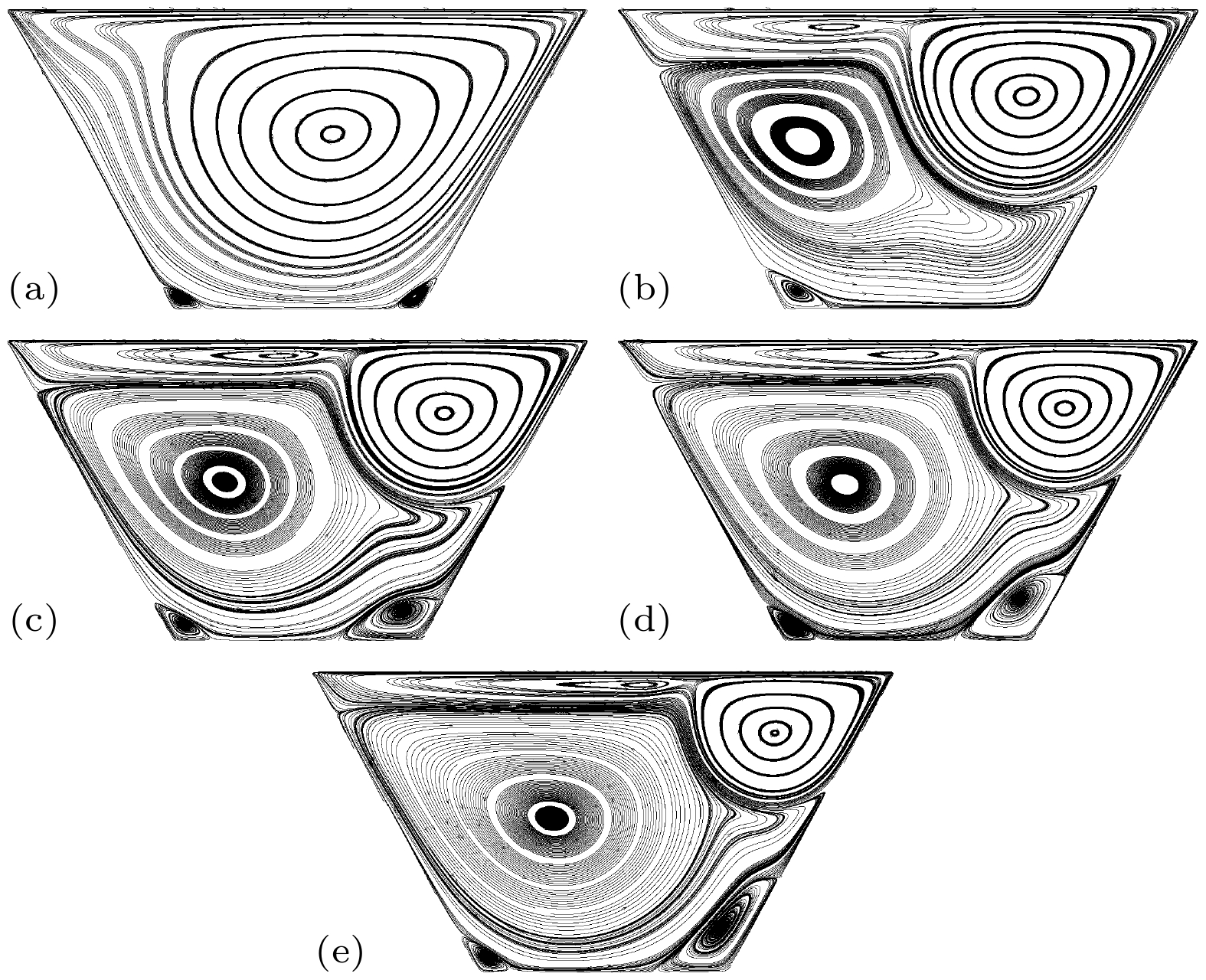
$ t=6000000 $ ; (b) velocity phase diagram at the velocity monitoring point; (c) velocity over time at the velocity monitoring point图 18 Case T2a条件下, Re为1000—10000时的流场形态 (a) Re = 1000; (b) Re = 3200; (c) Re = 5000; (d) Re = 6000; (e) Re = 8000; (f) Re = 10000
Fig. 18. Stream function contours of Reynolds numbers from 1000 to 10000 for Case T2a: (a) Re = 1000; (b) Re = 3200; (c) Re = 5000; (d) Re = 6000; (e) Re = 8000; (f) Re = 10000
图 20 Case T2a条件下, Re = 12500时呈现周期性非稳态流动 (a)时间步
$ t=6000000 $ 时的流场图; (b)监控点处速度相图; (c)速度监控点处速度随时间的变化Fig. 20. Stream function contours are periodic and unsteady at Re = 12500 for Case T2a: (a) Stream function contours at time steps
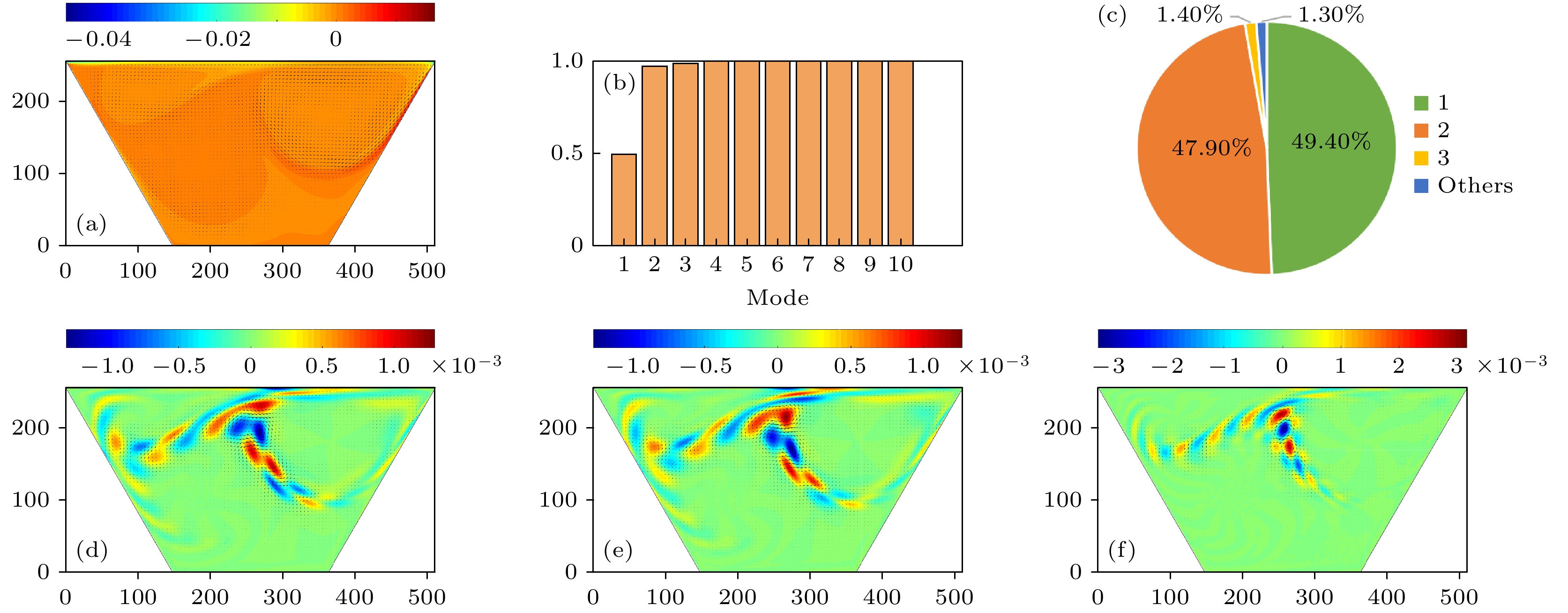
$ t=6000000 $ ; (b) velocity phase diagram at the velocity monitoring point; (c) velocity over time at the velocity monitoring point图 21 Case T2a条件下, Re = 12500时的各阶模态图 (a)速度平均场模态图; (b)前n 阶模态的能量占比; (c)各阶模态的能量占比; (d)—(f)一阶、二阶、三阶速度模态图
Fig. 21. Each order of mode for Case T2a when Re = 12500: (a) The mean field modal diagrams of velocity; (b) energy share of the first n order of mode for velocity; (c) energy share of each order of mode for velocity; (d)–(f) the first-order, second-order and third-order mode of velocity
图 22 Case T2a条件下, Re = 15000时呈现周期性非稳态流动 (a)时间步
$ t=6000000 $ 时的流场图; (b) 监控点处速度相图; (c)速度监控点处速度随时间的变化Fig. 22. Stream function contours are periodic and unsteady at Re = 15000 for Case T2a: (a) Stream function contours at time steps
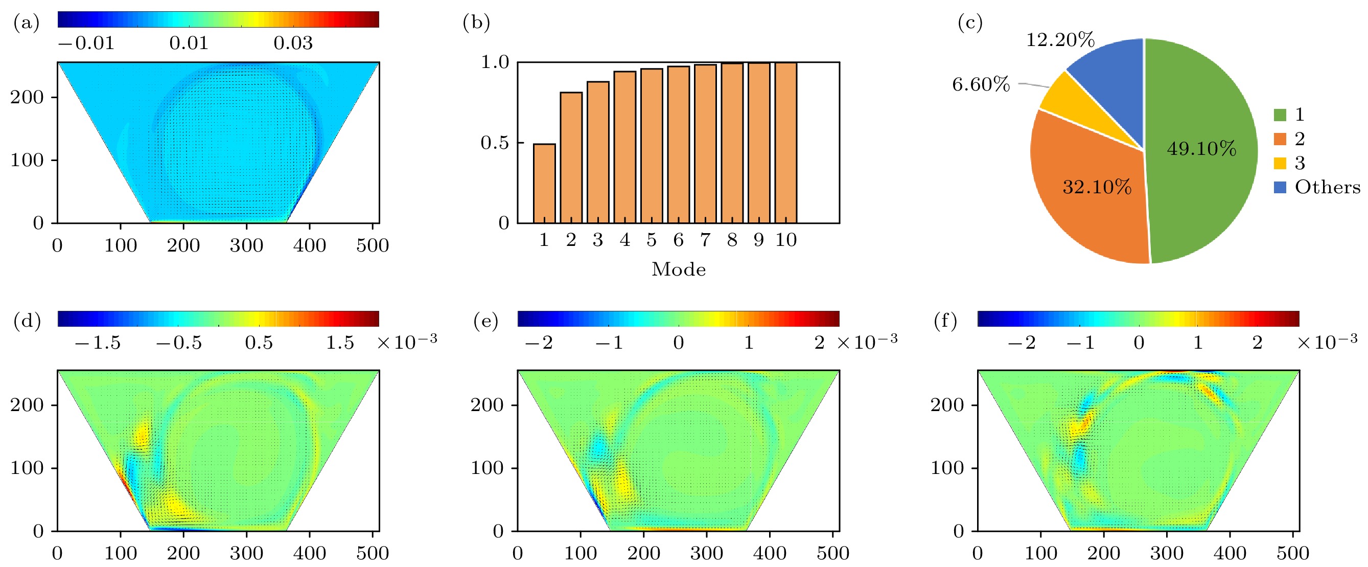
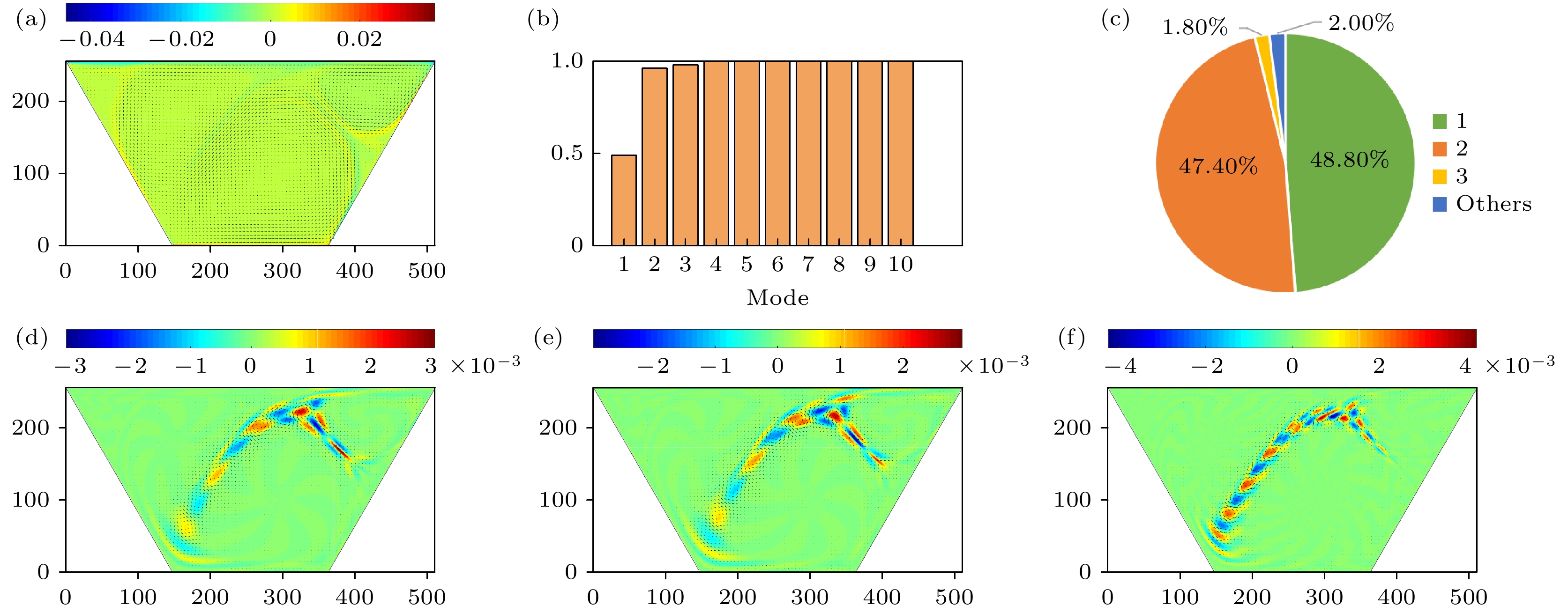
$ t=6000000 $ ; (b) velocity phase diagram at the velocity monitoring point; (c) velocity over time at the velocity monitoring point图 23 Case T2a条件下, Re = 15000时的各阶模态图 (a)速度平均场模态图; (b)前n阶模态的能量占比; (c)各阶模态的能量占比; (d)—(f)一阶、二阶、三阶速度模态图
Fig. 23. Each order of mode for Case T2a when Re = 15000: (a) The mean field modal diagrams of velocity; (b) energy share of the first n order of mode for velocity; (c) energy share of each order of mode for velocity; (d)–(f) the first-order, second-order and third-order mode of velocity
图 24 Case T2a条件下, Re = 20000时呈现非周期非稳态流动 (a)时间步
$ t=6000000 $ 时的流场图; (b)监控点处速度相图; (c)速度监控点处速度随时间的变化Fig. 24. Stream function contours are non-periodic and unsteady at Re = 20000 for Case T2a: (a) Stream function contours at time steps
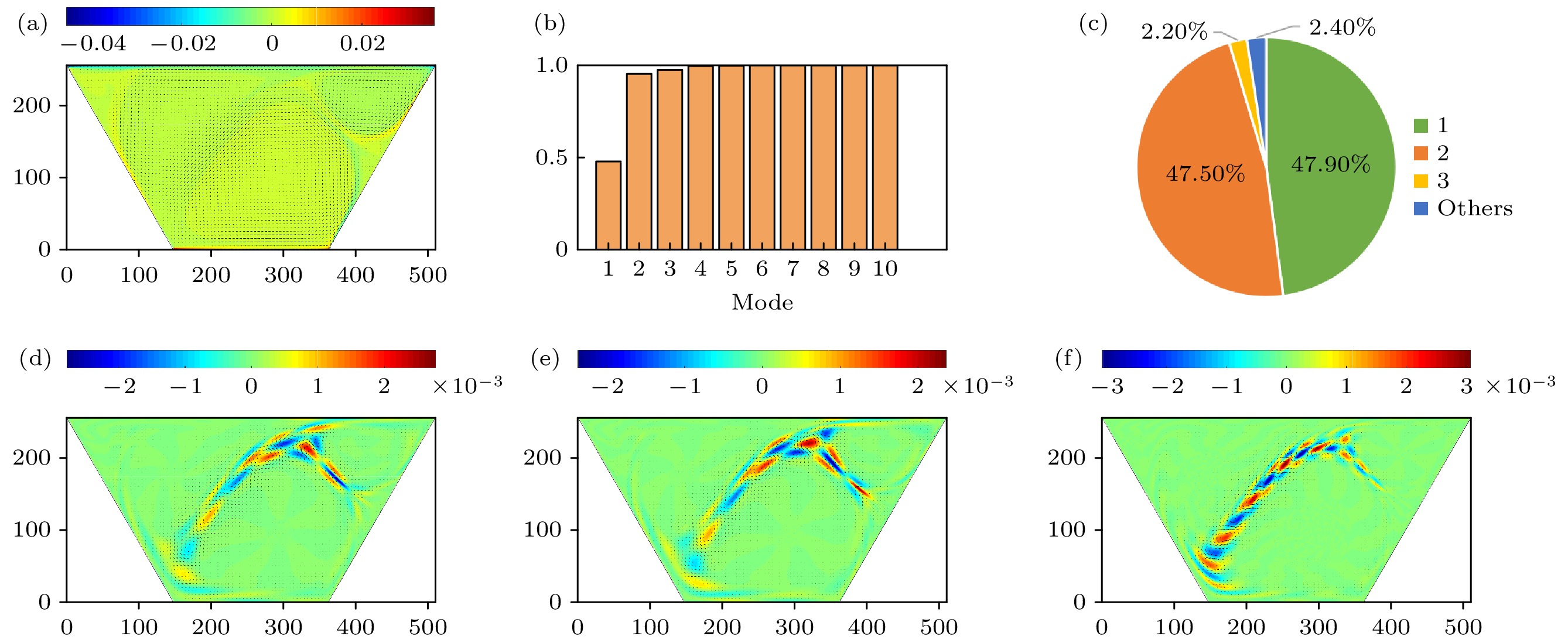
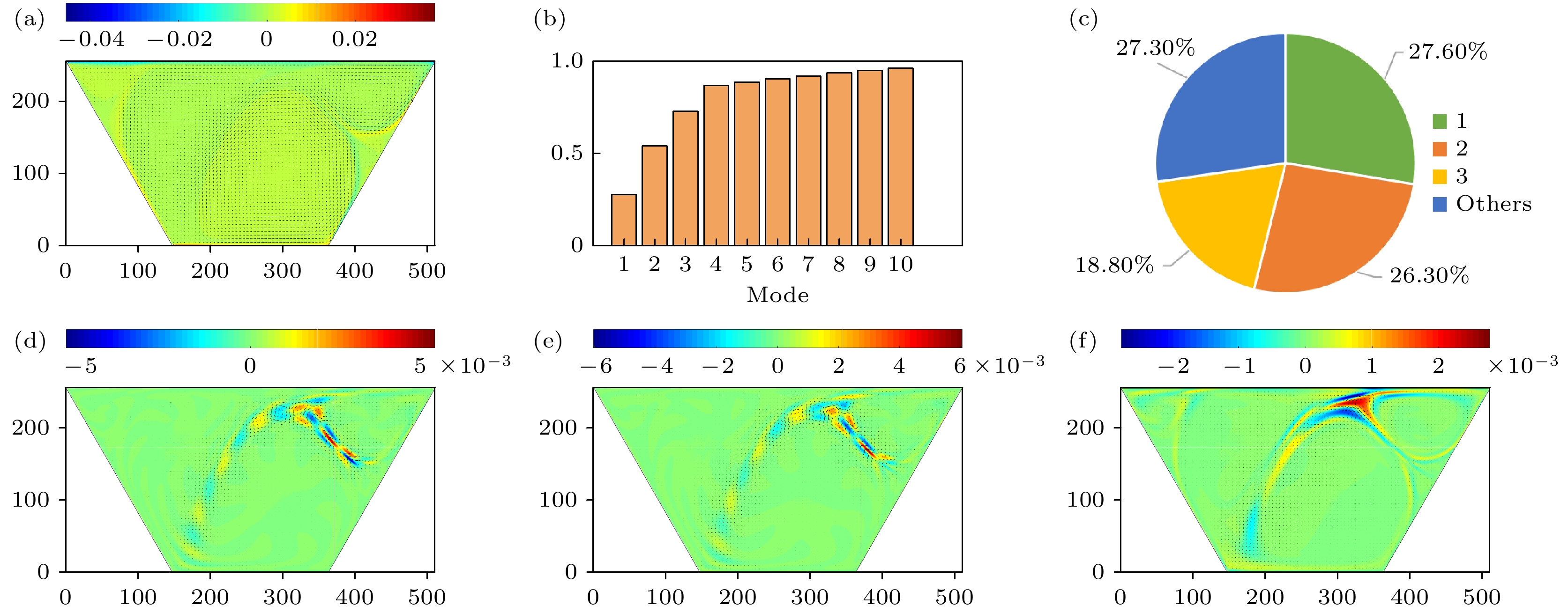
$ t=6000000 $ ; (b) velocity phase diagram at the velocity monitoring point; (c) velocity over time at the velocity monitoring point图 25 Case T2a条件下, Re = 20000时的各阶模态图 (a)速度平均场模态图; (b)前n阶模态的能量占比; (c)各阶模态的能量占比; (d)—(f)一阶、二阶、三阶速度模态图
Fig. 25. Each order of mode for Case T2a when Re = 20000: (a) The mean field modal diagrams of velocity; (b) energy share of the first n order of mode for velocity; (c) energy share of each order of mode for velocity; (d)–(f) the first-order, second-order and third-order mode of velocity.
图 26 Case T2a条件下, Re = 25000时呈非周期非稳态流动 (a)时间步
$ t=8000000 $ 时的流场图; (b)监控点处速度相图; (c)速度监控点处速度随时间的变化Fig. 26. Stream function contours are non-periodic and unsteady at Re = 25000 for Case T2a: (a) Stream function contours at time steps
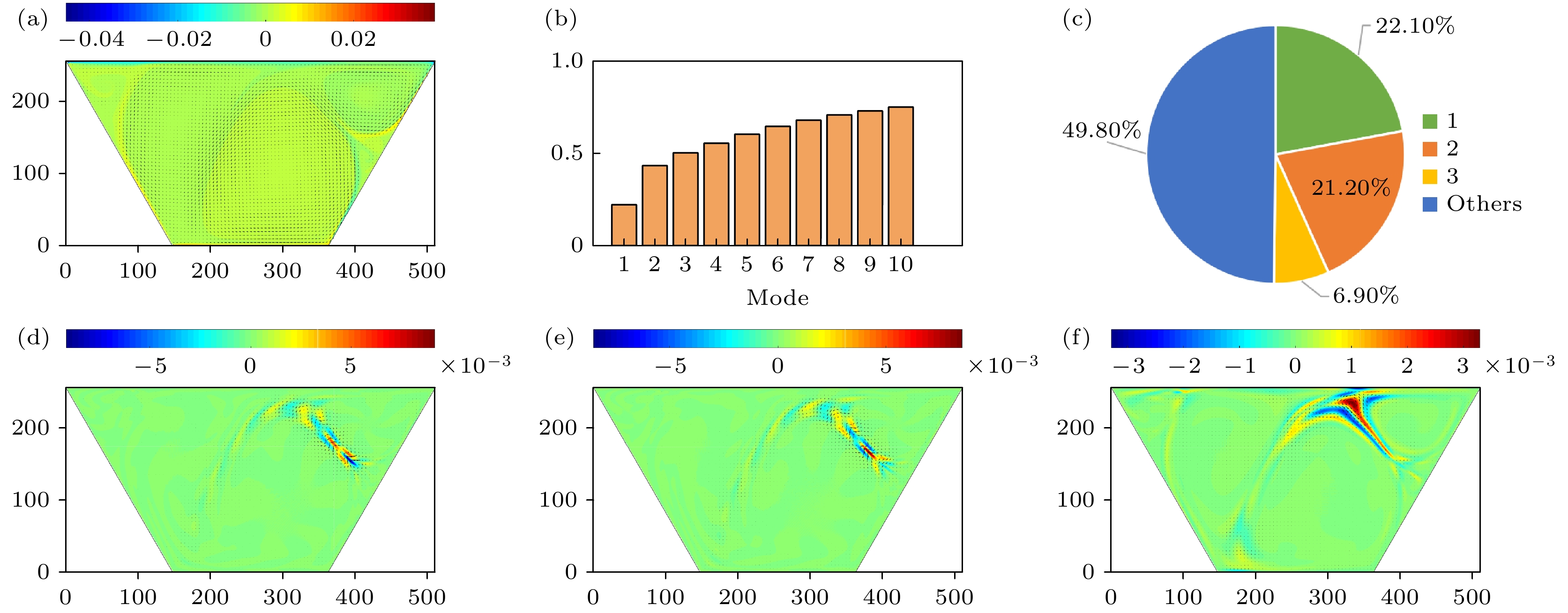
$ t=8000000 $ ; (b) velocity phase diagram at the velocity monitoring point; (c) velocity over time at the velocity monitoring point图 27 Case T2a条件下, Re = 25000时的各阶模态图 (a)速度平均场模态图; (b)前n阶模态的能量占比; (c)各阶模态的能量占比; (d)—(f)一阶、二阶、三阶速度模态图
Fig. 27. Each order of mode for Case T2a when Re = 25000: (a) The mean field modal diagrams of velocity; (b) energy share of the first n order of mode for velocity; (c) energy share of each order of mode for velocity; (d)–(f) the first-order, second-order and third-order mode of velocity
图 30 Case T2b条件下, Re = 6000时呈现周期性非稳态流动 (a)时间步
$ t=3000000 $ 时的流场图; (b)监控点处速度相图; (c)速度监控点处速度随时间的变化Fig. 30. Stream function contours are periodic and unsteady at Re = 6000 for Case T2b: (a) Stream function contours at time steps
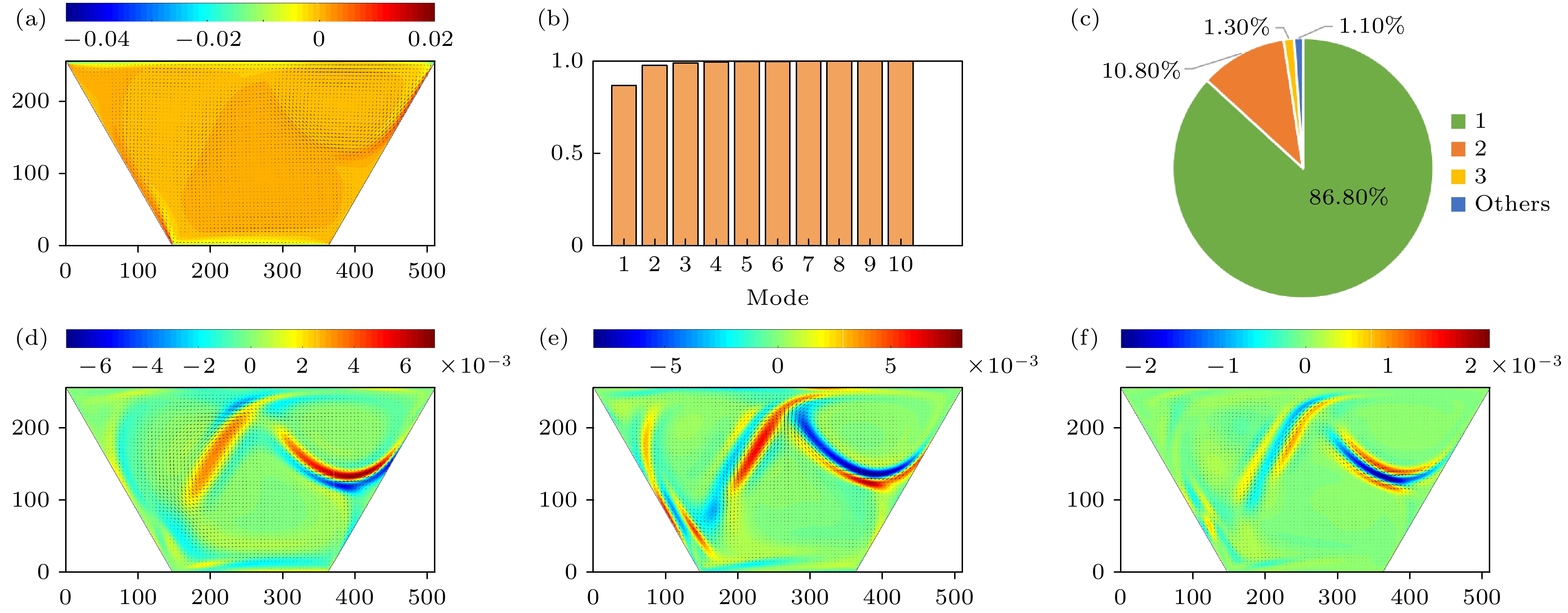
$ t=3000000 $ ; (b) velocity phase diagram at the velocity monitoring point; (c) velocity over time at the velocity monitoring point图 31 Case T2b条件下, Re = 6000时的各阶模态图 (a)速度平均场模态图; (b)前n阶模态的能量占比; (c)各阶模态的能量占比; (d)—(f)一阶、二阶、三阶速度模态图
Fig. 31. Each order of mode for Case T2b when Re = 6000: (a) The mean field modal diagrams of velocity; (b) energy share of the first n order of mode for velocity; (c) energy share of each order of mode for velocity; (d)–(f) the first-order, second-order and third-order mode of velocity
图 32 Case T2b条件下, Re = 8000时呈现非周期非稳态流动 (a)时间步
$ t=5000000 $ 时的流场图; (b)监控点处速度相图; (c)速度监控点处速度随时间变化图Fig. 32. Stream function contours are non-periodic and unsteady at Re = 8000 for Case T2b: (a) Stream function contours at time steps
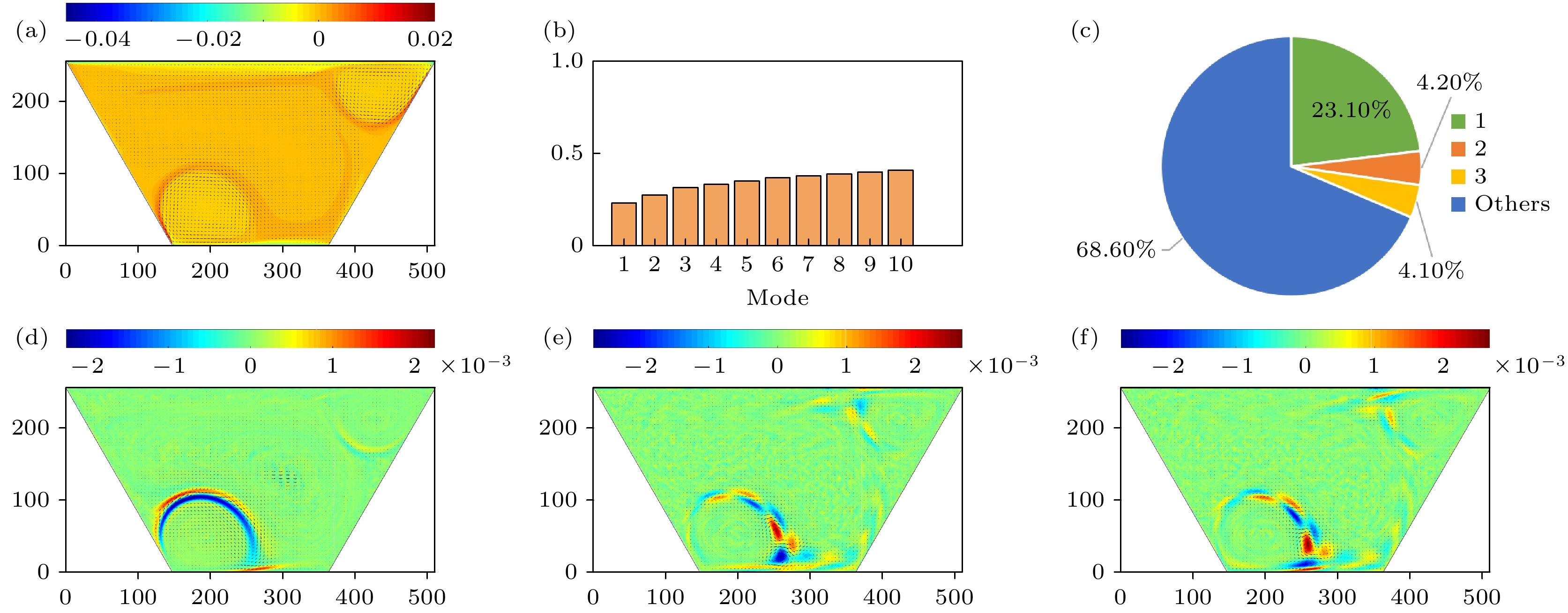
$ t=5000000 $ ; (b) velocity phase diagram at the velocity monitoring point; (c) velocity over time at the velocity monitoring point图 33 Case T2b条件下, Re = 8000时的各阶模态图 (a)速度平均场模态图; (b)前n阶模态的能量占比; (c)各阶模态的能量占比; (d)—(f)一阶、二阶、三阶速度模态图
Fig. 33. Each order of mode for Case T2b when Re = 8000: (a) The mean field modal diagrams of velocity; (b) energy share of the first n order of mode for velocity; (c) energy share of each order of mode for velocity; (d)–(f) the first-order, second-order and third-order mode of velocity
图 34 Case T2b条件下, Re = 10000时呈现非周期性非稳态流动 (a)时间步
$ t=10000000 $ 时的流场图; (b)监控点处速度相图; (c)速度监控点处速度随时间的变化Fig. 34. Stream function contours are non-periodic and unsteady at Re = 10000 for Case T2b: (a) Stream function contours at time steps
$ t=10000000 $ ; (b) velocity phase diagram at the velocity monitoring point; (c) velocity over time at the velocity monitoring point图 35 Case T2b条件下, Re = 10000时的各阶模态图 (a) 速度平均场模态图; (b)前n阶模态的能量占比; (c)各阶模态的能量占比; (d)—(f)一阶、二阶、三阶速度模态图
Fig. 35. Each order of mode for Case T2b when Re = 10000: (a) The mean field modal diagrams of velocity; (b) energy share of the first n order of mode for velocity; (c) energy share of each order of mode for velocity; (d)–(f) the first-order, second-order and third-order mode of velocity
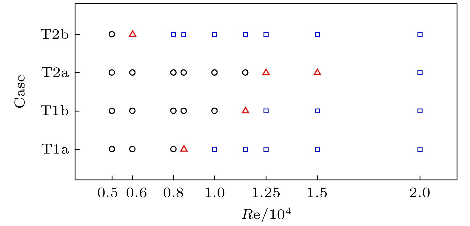
图 36 4种驱动情况下, Re对流场形态的影响图. 黑色圆圈表示流场处于稳态流动状态, 红色三角形表示流场处于周期性非稳态流动状态, 蓝色方框表示流场处于非周期性非稳态流动状态
Fig. 36. Effect of Reynolds number on the flow pattern for four different cases. The black circle indicates that the flow field is steady, the red triangle shows that the flow field is periodic but still unsteady, and the blue box indicates that the flow field is non-periodic and unsteady
表 1 CPU, OpenAcc, CUDA的计算时间和加速比
Table 1. Compute time and acceleration ratio of CPU, OpenAcc, CUDA
计算方式 CPU OpenAcc CUDA 加速比(CPU/OpenAcc) 加速比(CPU/CUDA) 计算时间/s 6459.28 408.75 48.95 15.80 131.96 表 2 对比Re = 100, 1000, 3200时流场中的涡心位置
Table 2. Comparison of the vortex center position in the cavity at Re = 100, 1000, 3200
Re $x_1$ $y_1$ $x_2$ $y_2$ $x_{\rm 2 l}$ $x_{\rm 2 r}$ $y_{\rm 2 l}$ $y_{\rm 2 r}$ 100 Zhang et al.[37] 0.5721 0.4212 — — — — Present 0.5722 0.4210 — — — — Error/% 0.03 0.05 — — — — 1000 Zhang et al.[37] 0.5473 0.3558 0.3423 0.0180 0.6351 0.0450 Present 0.5479 0.3561 0.3428 0.0179 0.6370 0.0451 Error/% 0.11 0.09 0.15 0.42 0.30 0.12 3200 Zhang et al.[37] 0.714 0.4392 0.3378 0.3491 0.4504 0.0788 Present 0.7225 0.4448 0.3427 0.3432 0.4539 0.0809 Error/% 1.18 1.28 1.46 1.70 0.77 2.66 表 3 Case T1a条件下, Re = 1000, 3200, 5000, 6000, 8000时流场中一级涡、二级涡和三级涡的涡心位置
Table 3. The first, second and third primary eddies characteristics at Re = 1000, 3200, 5000, 6000, 8000 for Case T1a.
Re $x_1$ $y_1$ $x_2$ $y_2$ $x_3$ $y_3$ $x_{\rm 2 l}$ $x_{\rm 2 r}$ $y_{\rm 2 l}$ $y_{\rm 2 r}$ $x_{\rm 3 l}$ $x_{\rm 3 r}$ $y_{\rm 3 l}$ $y_{\rm 3 r}$ 1000 286.89 148.44 153.65 358.66 9.93 11.39 — — — — 3200 359.03 180.97 163.84 158.09 142.90 15.17 — — — — 5000 192.02 134.52 241.44 384.21 241.30 192.66 155.94 347.52 13.77 25.36 6000 200.42 132.50 261.28 393.16 242.12 196.81 155.06 353.98 12.93 35.50 8000 210.51 130.69 290.17 405.75 243.39 202.60 154.62 358.04 12.48 37.51 表 4 Case T1b条件下, Re = 1000, 3200, 5000, 6000, 8000时流场中一级涡, 二级涡和三级涡的涡心位置
Table 4. The first, second and third primary eddies characteristics at Re = 1000, 3200, 5000, 6000, 8000 for Case T1b.
Re $x_1$ $y_1$ $x_2$ $y_2$ $x_3$ $y_3$ $x_{\rm 2 l}$ $x_{\rm 2 r}$ $y_{\rm 2 l}$ $y_{\rm 2 r}$ $x_{\rm 3 l}$ $x_{\rm 3 r}$ $y_{\rm 3 l}$ $y_{\rm 3 r}$ 1000 282.15 113.99 102.26 426.01 194.18 207.84 17.85 492.65 237.54 247.61 3200 280.78 118.95 110.43 412.34 158.93 218.72 25.99 487.95 229.41 245.42 5000 280.79 118.95 110.43 412.34 158.95 218.72 25.97 487.81 229.78 245.57 6000 280.79 118.95 110.43 412.34 158.94 218.73 26.10 487.84 229.99 245.57 8000 283.22 121.00 121.00 408.63 117.03 222.46 61.80 469.33 210.11 233.00 表 5 Case T2a条件下, Re = 1000, 3200, 5000, 6000, 8000, 10000时流场中的涡心位置
Table 5. The first, second and third primary eddies characteristics at Re = 1000, 3200, 5000, 6000, 8000, 10000 for Case T2a.
Re $x_1$ $y_1$ $x_2$ $y_2$ $x_3$ $y_3$ $x_{\rm 2 l}$ $x_{\rm 2 r}$ $y_{\rm 2 l}$ $y_{\rm 2 r}$ $x_{\rm 3 l}$ $x_{\rm 3 r}$ $y_{\rm 3 l}$ $y_{\rm 3 r}$ $x_{\rm 3 r_1}$ $x_{\rm 3 r_2}$ $y_{\rm 3 r_1}$ $y_{\rm 3 r_2}$ 1000 265.65 83.21 166.69 390.56 209.14 202.40 — 412.69 422.93 — 101.61 117.56 3200 276.64 90.43 139.51 404.39 190.46 205.49 34.89 410.36 421.46 216.82 115.62 134.97 5000 282.10 92.07 141.76 408.64 186.10 206.44 40.16 410.52 421.23 222.49 120.92 138.91 6000 284.21 92.69 142.88 410.13 184.42 206.76 41.25 410.77 421.29 223.56 122.65 140.12 8000 287.07 93.68 144.54 412.15 182.08 207.14 42.18 411.69 422.02 224.22 124.32 141.38 10000 288.94 94.48 145.67 413.49 180.45 207.33 43.32 412.89 423.35 223.99 124.48 141.80 表 6 Case T2b条件下, Re = 1000, 3200, 5000时流场中的涡心位置
Table 6. The first, second and third primary eddies characteristics at Re = 1000, 3200, 5000 for Case T2b.
Re $x_1$ $y_1$ $x_2$ $y_2$ $x_3$ $y_3$ $x_{3 {\rm l}}$ $x_{3 {\rm r} }$ $y_{3 {\rm l} }$ $y_{3 {\rm r}}$ 1000 259.99 132.44 59.83 183.94 — — — — 3200 260.97 131.12 66.16 206.26 84.50 369.55 245.42 14.67 5000 261.42 130.74 65.46 208.22 88.80 365.54 246.86 14.39 -
[1] Peng Y F, Shiau Y H, Hwang R R 2003 Comput. Fluids 32 337
 Google Scholar
[2] Isaev S A, Baranov P A, Sudakov A G, et al. 2008 Thermophys. Aeromech. 15 463
 Google Scholar
[3] Balachandar S, Eaton J K 2010 Annu. Rev. Fluid Mech. 42 111
 Google Scholar
[4] Kuhlmann H C, Romanò F 2019 The Lid-Driven Cavity (Austria: Springer International Publishing) p233
[5] Nonino C, Del Giudice S 1988 Int. J. Numer. Methods Eng. 25 313
 Google Scholar
[6] Alleborn N, Raszillier H, Durst F 1999 Int. J. Heat Mass Tran. 42 833
 Google Scholar
[7] Talebi F, Mahmoudi A H, Shahi M 2010 Int. Commun. Heat Mass 37 79
 Google Scholar
[8] Chowdhury M, Kumar B V R 2023 J. Nonnewton. Fluid Mech. 312 104975
 Google Scholar
[9] Ribbens C J, Watson L T, Wang C Y 1994 J. Comput. Phys. 112 173
 Google Scholar
[10] McQuain W D, Ribbens C J, Wang C Y, et al. 1994 Comput. Fluids 23 613
 Google Scholar
[11] Ismael M A, Chamkha A J 2015 Numer. Heat Transfer, Part A 68 312
 Google Scholar
[12] Mebarek-Oudina F, Laouira H, Hussein A K, et al. 2022 Mathematics 10 929
 Google Scholar
[13] Mondal P, Mahapatra T R 2021 Int. J. Mech. Sci. 208 106665
 Google Scholar
[14] Kareem A K, Mohammed H A, Hussein A K, et al. 2016 Int. Commun. Heat Mass 77 195
 Google Scholar
[15] Rashad A M, Sivasankaran S, Mansour M A, et al. 2017 Numer. Heat Transfer, Part A 71 1223
 Google Scholar
[16] Darr J H, Vanka S P 1991 Phys. Fluids 3 385
 Google Scholar
[17] Paramane S B, Sharma A 2008 Numer. Heat Transfer, Part B 54 84
 Google Scholar
[18] 张恒, 任峰, 胡海豹 2021 70 184703
 Google Scholar
Zhang H, Ren F, Hu H B 2021 Acta Phys. Sin. 70 184703
 Google Scholar
[19] Yang F, Shi X, Guo X, et al. 2012 Energy Procedia 16 639
 Google Scholar
[20] Nagendra K, Lakshmisha K N 2009 Int. J. Numer. Methods Heat Fluid Flow 19 790
 Google Scholar
[21] Perumal D A, Dass A K 2011 Comput. Math. Appl. 61 3711
 Google Scholar
[22] Nemati H, Farhadi M, Sedighi K, et al. 2010 Int. Commun. Heat Mass 37 1528
 Google Scholar
[23] Guo X, Zhong C, Zhuo C, et al. 2014 Theor. Comput. Fluid Dyn. 28 215
 Google Scholar
[24] Patil D V, Lakshmisha K N, Rogg B 2006 Comput. Fluids 35 1116
 Google Scholar
[25] Hou S, Zou Q, Chen S, et al. 1995 J. Comput. Phys. 118 329
 Google Scholar
[26] Chai Z H, Shi B C, Zheng L 2006 Chin. Phys. 15 1855
 Google Scholar
[27] Yuana K A, Budiana E P 2019 IOP Conf. Ser.: Mater. Sci. Eng. 546 052088
 Google Scholar
[28] Perumal D A, Dass A K 2008 WIT Trans. Eng. Sci. 59 45
 Google Scholar
[29] Bo A N, Mellibovsky F, Bergada J M, et al. 2020 Appl. Math. Modell. 82 469
 Google Scholar
[30] Shahid H, Yaqoob I, Khan W A, et al. 2021 Int. Commun. Heat Mass 129 105658
 Google Scholar
[31] Perumal D A 2018 Therm. Sci. Eng. Prog. 6 48
 Google Scholar
[32] Guo Y, Bennacer R, Shen S, et al. 2010 Int. J. Numer. Methods Heat Fluid Flow 20 130
 Google Scholar
[33] Shahid H, Yaqoob I, Khan W A, et al. 2021 Int. Commun. Heat Mass 128 105552
 Google Scholar
[34] An B, Bergada J M, Mellibovsky F 2019 J. Fluid Mech. 875 476
 Google Scholar
[35] An B, Guo S, Bergadà J M 2023 Appl. Sci. 13 888
 Google Scholar
[36] Sidik N A C, Munir F A 2012 Arab. J. Sci. Eng. 37 1723
 Google Scholar
[37] Zhang T, Shi B, Chai Z 2010 Compu. Fluids 39 1977
 Google Scholar
[38] Qian Y H, D’Humières D, Lallemand P 1992 EPL 17 479
 Google Scholar
[39] Ziegler D P 1993 J. Stat. Phys. 71 1171
 Google Scholar
[40] Guo Z L, Zheng C G, Shi B C 2002 Chin. Phys. 11 366
 Google Scholar
[41] Guo Z L, Zheng C G, Shi B C 2002 Phys. Fluids 14 2007
 Google Scholar
计量
- 文章访问数: 5695
- PDF下载量: 88
- 被引次数: 0


 下载:
下载:
