-
通过在电解液中引入氧化还原活性物质可以有效提高能量密度且不降低功率密度. 考虑到离子电导率以及环境安全等因素, 本文在传统酸性凝胶电解质PVA/H3PO4中引入了氧化还原特性的有机小分子物质—对苯二酚(HQ), 然后与具有高比表面积及垂直取向结构的碳纳米管阵列(ACNT)进行复合, 设计制备了对称“三明治”结构的氧化还原增强型固态超级电容器ACNT@PVA@HQ, 并系统研究了碳管取向结构以及孔隙间隙对ACNT@PVA@HQ器件电化学性能以及电荷储存机理的影响. 实验表明, 极少量对苯二酚活性物质(0.1%, 摩尔分数)的加入, 可以使ACNT@PVA@HQ器件的体积比容量相比纯ACNT@PVA器件提升6.4倍, 同时保持了极高的倍率性能和循环稳定性. 进一步利用溶剂蒸发的方法制备了高密度取向的碳管阵列(DACNT), 组装的DACNT@PVA@HQ器件在电流密度11.1 mA·cm–2下, 其比电容量高达385 mF·cm–2 (1674 mF·cm–3), 在平均功率密度大小为0.96 mW·cm–2 (4.17 mW·cm–3)的条件下, 其最大能量密度可以达到0.06 mW·h·cm–2 (0.26 mW·h·cm–3), 优于众多文献报道的结果. 实验证明取向结构的阵列可以有效缩短离子迁移路径, 提高电荷的转移效率, 使得器件具有良好的倍率性能和更低的内阻. 这种新型的氧化还原增强型超级电容器不但具有优秀的电化学储能性质, 还满足环保、安全的理念, 为未来新能源装置的开发提供了新思路, 具有良好的应用前景.By introducing redox active substances into electrolyte, the energy density can be effectively increased without reducing the power density. Considering the influence of ionic conductivity and environmental safety, we introduce the redox small molecule hydroquinone (HQ) into the PVA/H3PO4 gel electrolyte, which then will recombine with the carbon nanotube arrays (ACNT) possessing high specific surface area and vertical orientation structure. The symmetrical “sandwich” type redox-enhanced solid-state super capacitor is then designed and prepared. We systematically study the effects of oriented structure and pore space on the electrochemical properties of the ACNT@PVA@HQ device and charge storage mechanism. With the addition of hydroquinone (0.1%, mol%), the specific capacitance of ACNT@PVA@HQ composite device increases 6.4 times compared with that of the ACNT@PVA, and maintains the extremely high rate performance and cyclic stability. When the current density increases 10 times, the specific capacitance of the device still possesses 85% of the original value. The energy storage mechanism is mainly ascribed to a diffusion-control behavior at a low scan rate while it will change into a capacitive behavior at a high scan speed. Furthermore, we prepare highly densified oriented carbon nanotube arrays (DACNT) by solvent evaporation, enhancing the mechanical stability of carbon nanotube arrays and improving the specific capacitance and energy density of the devices. Compared with the specific capacitance of ACNT and random carbon nanotube (CCNT), that of DACNT@PVA@HQ device under the current density of 11.1 mA·cm–2 increases up to 385 mF·cm–2 (1674 mF·cm–3), which is 6.6 times higher than that of the CCNT@PVA@HQ device and 18 times higher than that of the ACNT@PVA device. The maximum energy density can finally reach as high as 0.06 mW·h·cm–2 (0.26 mW·h·cm–3), which is much better than those of many other reported CNTs-based devices. The oriented structure of the arrays effectively shortens the ion migration path of the device, achieving a good rate performance and lower internal resistance. This new type of redox-enhanced solid-state supercapacitor not only has excellent electrochemical energy storage properties, but also meets the requirements for environmental protection and safety. This design provides a new idea for developing the new energy devices in the future, which has a good prospect in practical applications.
-
Keywords:
- carbon nanotube arrays /
- hydroquinone /
- solid state /
- flexible super-capacitor
[1] Gong M, Wan P, Ma D, Zhong M, Liao M, Ye J, Shi R, Zhang L 2019 Adv. Funct. Mater. 29 1902127
 Google Scholar
[2] Han T H, Kim H, Kwon S J, Lee T W 2017 Mater. Sci. Eng. R-Rep. 118 1
 Google Scholar
[3] Liu W, Song M S, Kong B, Cui Y 2017 Adv. Mater. 29 1603436
 Google Scholar
[4] Stoppa M, Chiolerio A 2014 Sensors (Basel) 14 11957
 Google Scholar
[5] Wang X, Lu X, Liu B, Chen D, Tong Y, Shen G 2014 Adv. Mater. 26 4763
 Google Scholar
[6] Xu G, Zheng C, Zhang Q, Huang J, Zhao M, Nie J, Wang X, Wei F 2011 Nano Res. 4 870
 Google Scholar
[7] Li P, Kong C, Shang Y, Shi E, Yu Y, Qian W, Wei F, Wei J, Wang K, Zhu H, Cao A, Wu D 2013 Nanoscale 5 8472
 Google Scholar
[8] Hu S, Rajamani R, Yu X 2012 Appl. Phys. Lett. 100 104103
 Google Scholar
[9] Shao Y, El-Kady M F, Wang L J, Zhang Q, Li Y, Wang H, Mousavi M F, Kaner R B 2015 Chem. Soc. Rev. 44 3639
 Google Scholar
[10] Lin R, Taberna P L, Chmiola J, Guay D, Gogotsi Y, Simon P 2009 J. Electrochem.Soc. 156 A7
 Google Scholar
[11] Guan C, Zhao W, Hu Y, Lai Z, Li X, Sun S, Zhang H, Cheetham A K, Wang J 2017 Nanoscale Horiz. 2 99
 Google Scholar
[12] He Y, Chen W, Li X, Zhang Z, Fu J, Zhao C, Xie E 2012 ACS Nano 7 174
 Google Scholar
[13] Li H, He J, Cao X, Kang L, He X, Xu H, Shi F, Jiang R, Lei Z, Liu Z H 2017 J. Power Sources 371 18
 Google Scholar
[14] Shi Y, Pan L, Liu B, Wang Y, Cui Y, Bao Z, Yu G 2014 J. Mater. Chem. A 2 6086
 Google Scholar
[15] Li W, Gao F, Wang X, Zhang N, Ma M 2016 Angew Chem. Int. Ed. Engl. 55 9196
 Google Scholar
[16] Evanko B, Boettcher S W, Yoo S J, Stucky G D 2017 ACS Energy Lett. 2 2581
 Google Scholar
[17] Roldan S, Blanco C, Granda M, Menendez R, Santamaria R 2011 Angew. Chem. Int. Ed. Engl. 50 1699
 Google Scholar
[18] Ma G, Dong M, Sun K, Feng E, Peng H, Lei Z 2015 J. Mater. Chem. A 3 4035
 Google Scholar
[19] Pan S, Deng J, Guan G, Zhang Y, Chen P, Ren J, Peng H 2015 J. Mater. Chem. A 3 6286
 Google Scholar
[20] Zhang H, Cao G, Yang Y 2009 Energy Environ. Sci. 2 932
 Google Scholar
[21] 巫梦丹, 叶安娜, 周胜林, 王敏, 张晓华, 杨朝晖 2019 68 108201
 Google Scholar
Wu M D, Ye A N, Zhou S L, Wang M, Zhang X H, Yang Z H 2019 Acta Phys. Sin. 68 108201
 Google Scholar
[22] Zhu Q, Yuan X, Zhu Y, Ni J, Zhang X, Yang Z 2018 Nanotechnology 29 195405
 Google Scholar
[23] Kim D, Lee G, Kim D, Yun J, Lee S S, Ha J S 2016 Nanoscale 8 15611
 Google Scholar
[24] Balamurugan J, Li C, Thanh T D, Park O, Kim N H, Lee J H 2017 J. Mater. Chem. A 5 19760
 Google Scholar
[25] Sathyamoorthi S, Suryanarayanan V, Velayutham D 2015 J. Power Sources 274 1135
 Google Scholar
[26] Zhong J, Fan L Q, Wu X, Wu J H, Liu G J, Lin J M, Huang M L, Wei Y L 2015 Electrochimica Acta 166 150
 Google Scholar
[27] Boota M, Hatzell K B, Kumbur E C, Gogotsi Y 2015 ChemSusChem 8 835
 Google Scholar
[28] Lindström H, Södergren S, Solbrand A, Rensmo H, Hjelm J, Hagfeldt A, Lindquist S E 1997 J. Phys. Chem. B 101 7717
 Google Scholar
[29] Yu H, Wu J, Fan L, Lin Y, Xu K, Tang Z, Lan Z 2012 J. Power Sources 198 402
 Google Scholar
[30] Hsia B, Marschewski J, Wang S, In J B, Carraro C, Poulikakos D, Grigoropoulos C P, Maboudian R 2014 Nanotechnology 25 055401
 Google Scholar
[31] Rajendran V, Mohan A, Jayaraman M, Nakagawa T 2019 Nano Energy 65 104055
 Google Scholar
[32] Li K, Liu X, Chen S, Pan W, Zhang J 2018 J. Energy Chem. 32 166
 Google Scholar
-
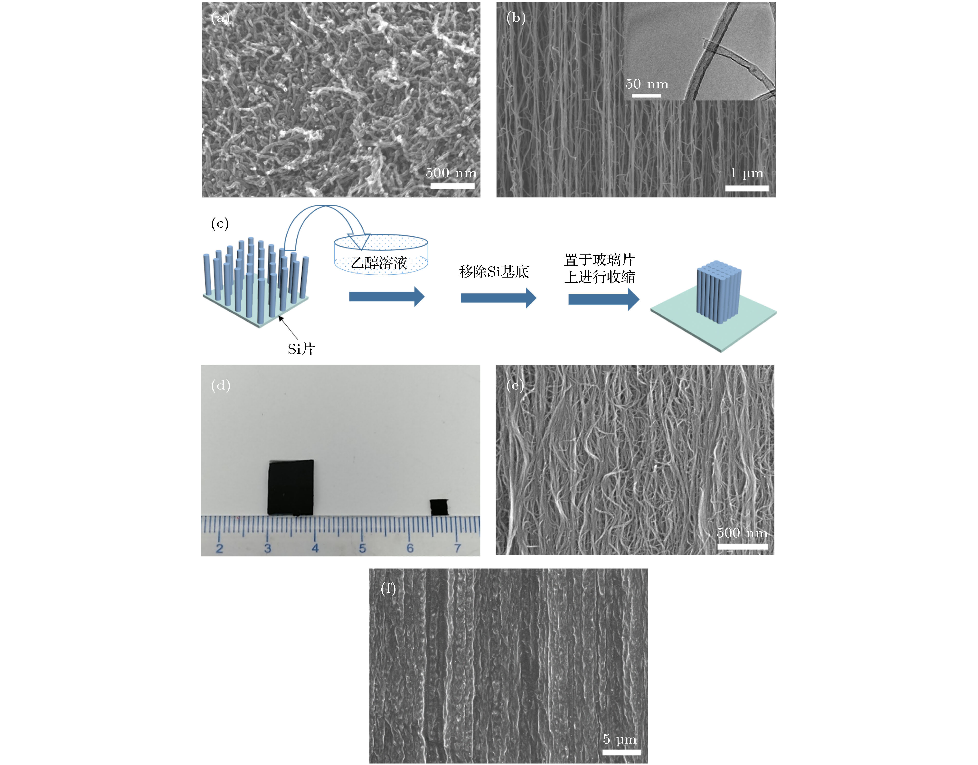
图 2 (a) CCNT的SEM图; (b) ACNT的SEM图(内部插图为单根碳纳米管TEM图); (c) DACNT制备过程图; (d)收缩前后阵列尺寸对比图; (e) DACNT的SEM 图; (f)凝胶包埋后ACNT@PVA@HQ复合膜SEM图
Fig. 2. (a) The SEM image of CCNT; (b) the SEM image of ACNT (insert: The TEM image of ACNT); (c) preparation process of the DACNT; (d) comparison of the arrays before and after shrinkage; (e) the SEM image of the DACNT; (f) the SEM image of the ACNT@PVA@HQ composite device.
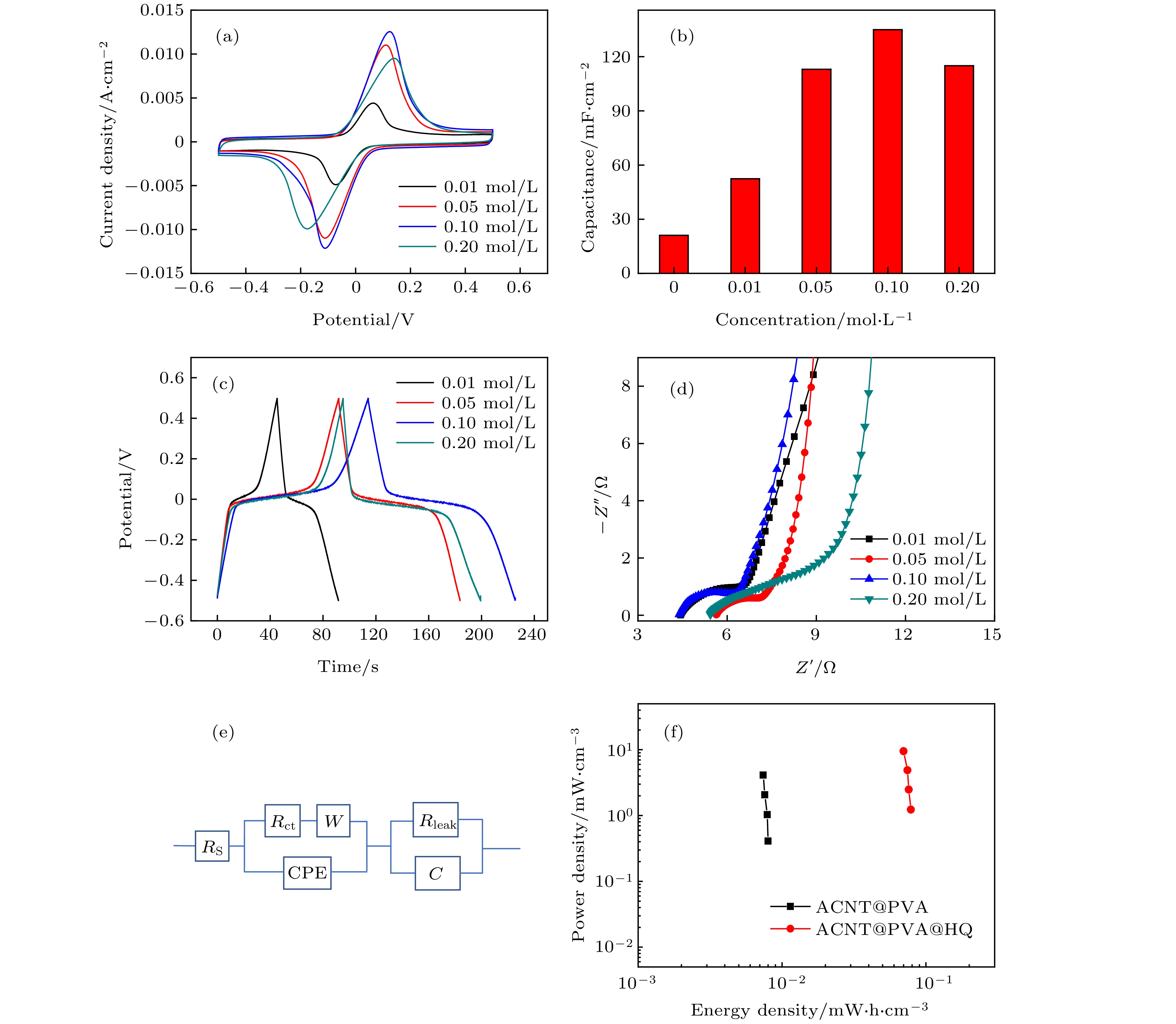
图 3 不同浓度下ACNT@PVA@HQ器件的电化学性能测试 (a)相同扫速(20 mV/s)下不同HQ添加量的器件CV对比图; (b)器件比容量随HQ浓度变化图; (c)相同电流密度(1.23 mA·cm–2)下的GCD曲线对比图; (d)交流阻抗谱对比图; (e)等效电路拟合模型图; (f) ACNT@PVA@HQ (0.1 mol/L)器件与ACNT@PVA器件Ragone对比图
Fig. 3. Electrochemical performance test of ACNT@PVA@HQ composite devices at different concentrations: (a) Comparison of CVs with different amounts of HQ addition under the same scan rate (20 mV/s); (b) area specific capacitance at different HQ concentrations; (c) GCD curves comparison diagram under the same current density (1.23 mA·cm–2); (d) alternating current impedance spectrogram of the samples at different concentrations; (e) the diagram of equivalent circuit fitting model; (f) comparison of Ragone plots between the devices of ACNT@PVA@HQ (0.1 mol/L) and ACNT@PVA
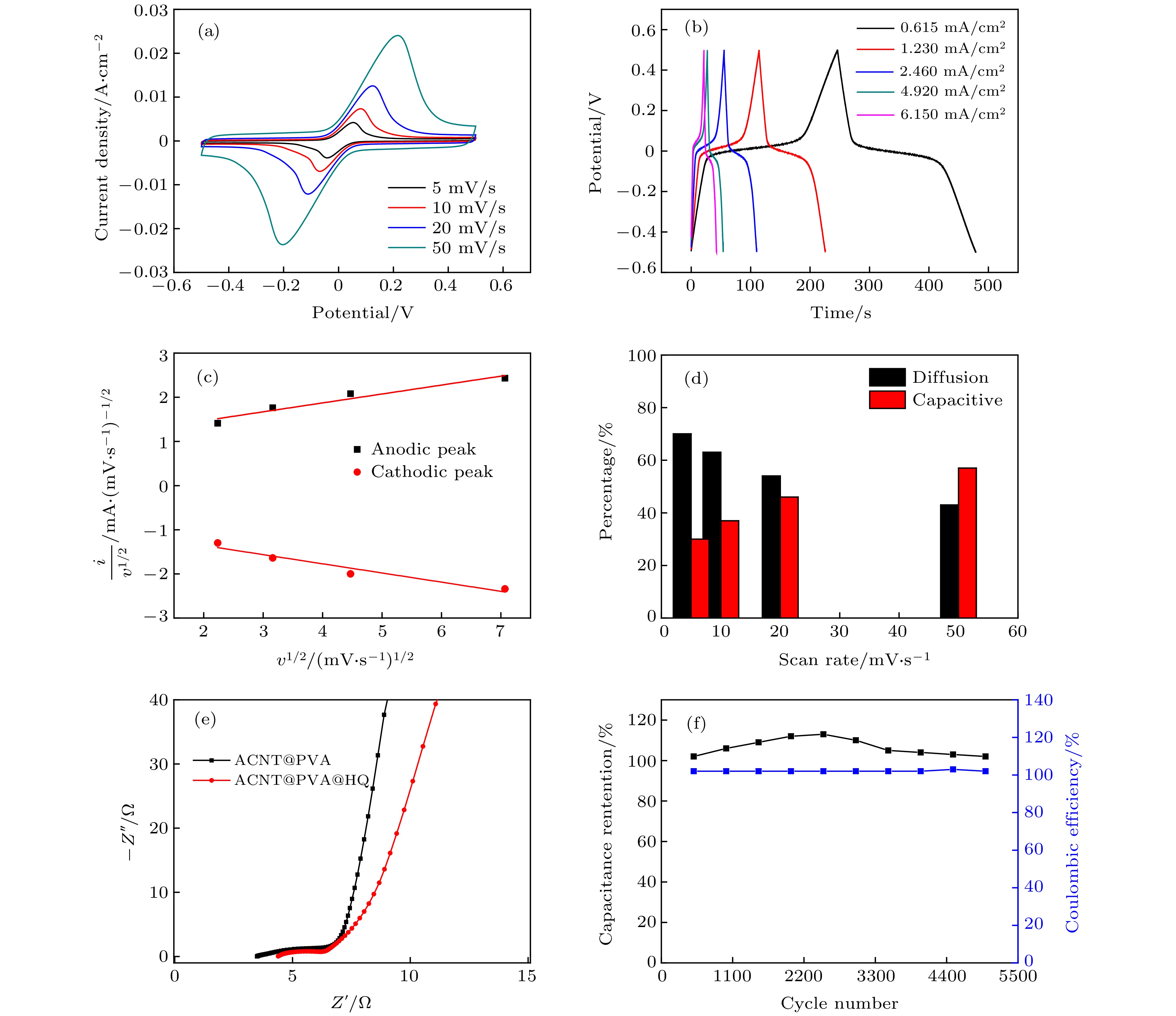
图 4 [HQ] = 0.1 mol/L浓度下ACNT@PVA@HQ器件的电化学性能测试 (a)循环伏安曲线图(5−50 mV/s); (b)不同电流密度(0.615−6.15 mA·cm–2)下的GCD曲线图; (c)峰电流与扫速的关系图; (d)容量贡献占比图; (e)交流阻抗谱图; (f) 5000次循环稳定性图
Fig. 4. Electrochemical performance test of the ACNT@PVA@HQ composite device at [HQ] = 0.1 mol/L: (a) CV curves at scan rates from 5 mV/s to 50 mV/s; (b) GCD curves under different current densities (0.615−6.15 mA·cm–2); (c) relationship between peak current and scan rates; (d) the proportion of capacitance contribution in composite device; (e) Nyquist plot at 0.01 Hz−100 kHz; (f) cyclic performance (5000 cycles) during charging-discharging cycles
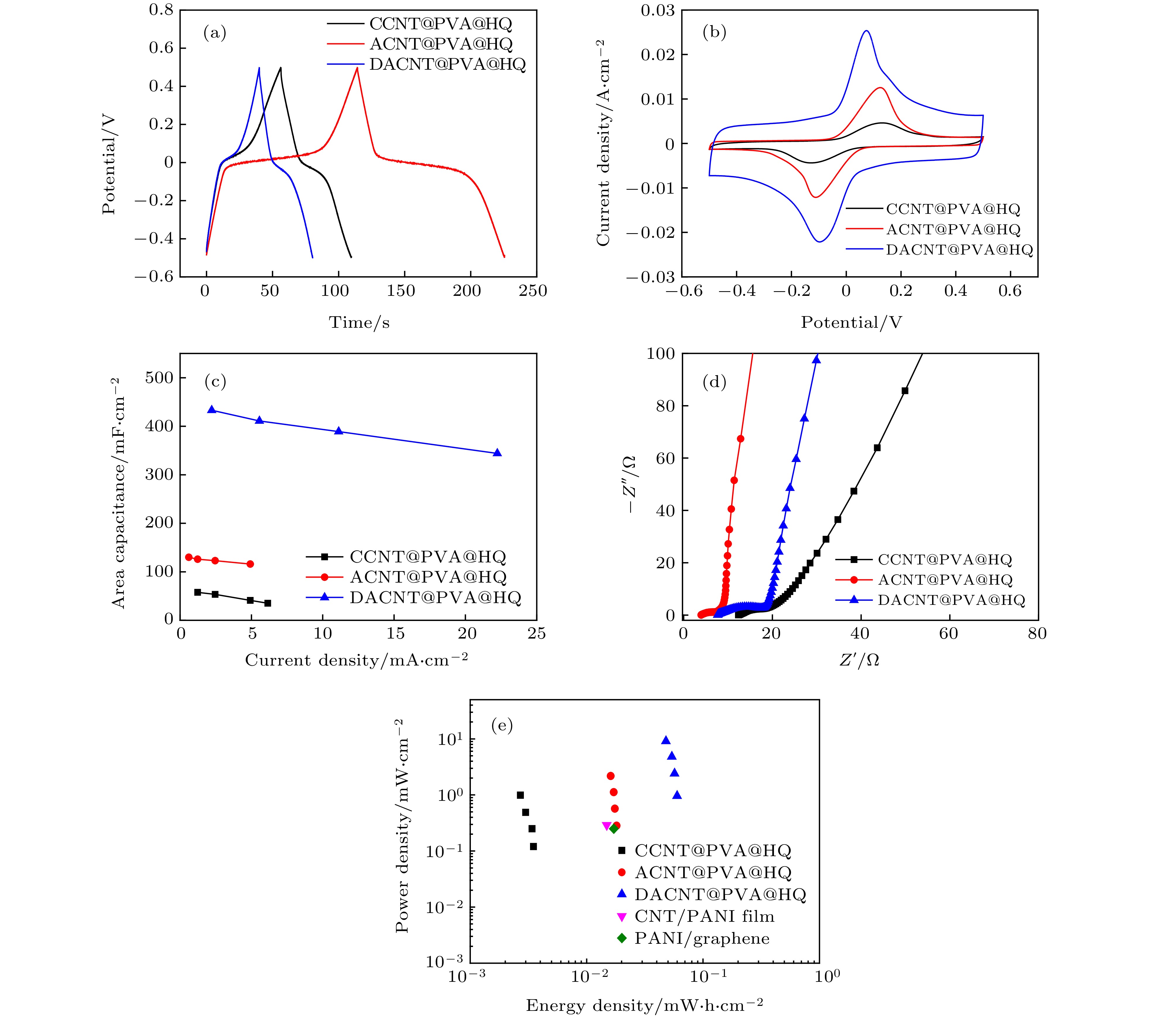
图 5 CCNT@PVA@HQ, ACNT@PVA@HQ 和 DACNT@PVA@HQ器件的电化学测试 (a) 相同电流(1 mA)下的GCD对比图; (b) 20 mV/s下的CVs对比图; (c)面积比容量随电流密度变化图; (d) EIS对比图; (e)器件功率密度-能量密度对比图
Fig. 5. Electrochemical test of CCNT@PVA@HQ, ACNT@PVA@HQ and DACNT@PVA@HQ composite devices: (a) Comparison of GCD curves with 1 mA; (b) CVs comparison diagram at 20 mV/s; (c) relationship between area specific capacitance and current densities; (d) comparison diagram of EIS; (e) Ragone plots of three kinds of composite device
表 1 不同样品相关测试数据对比
Table 1. Comparison of relevant test data of different samples
C/mF·cm–2
(20 mV/s)PS/mW·cm–2 ES/mW·h·cm–2 PVA@ACNT 21 0.09 0.00184 HQ@PVA@CCNT 72 0.12 0.00350 HQ@PVA@ACNT 135 0.28 0.01800 HQ@PVA@DACNT 425 0.96 0.06000 -
[1] Gong M, Wan P, Ma D, Zhong M, Liao M, Ye J, Shi R, Zhang L 2019 Adv. Funct. Mater. 29 1902127
 Google Scholar
[2] Han T H, Kim H, Kwon S J, Lee T W 2017 Mater. Sci. Eng. R-Rep. 118 1
 Google Scholar
[3] Liu W, Song M S, Kong B, Cui Y 2017 Adv. Mater. 29 1603436
 Google Scholar
[4] Stoppa M, Chiolerio A 2014 Sensors (Basel) 14 11957
 Google Scholar
[5] Wang X, Lu X, Liu B, Chen D, Tong Y, Shen G 2014 Adv. Mater. 26 4763
 Google Scholar
[6] Xu G, Zheng C, Zhang Q, Huang J, Zhao M, Nie J, Wang X, Wei F 2011 Nano Res. 4 870
 Google Scholar
[7] Li P, Kong C, Shang Y, Shi E, Yu Y, Qian W, Wei F, Wei J, Wang K, Zhu H, Cao A, Wu D 2013 Nanoscale 5 8472
 Google Scholar
[8] Hu S, Rajamani R, Yu X 2012 Appl. Phys. Lett. 100 104103
 Google Scholar
[9] Shao Y, El-Kady M F, Wang L J, Zhang Q, Li Y, Wang H, Mousavi M F, Kaner R B 2015 Chem. Soc. Rev. 44 3639
 Google Scholar
[10] Lin R, Taberna P L, Chmiola J, Guay D, Gogotsi Y, Simon P 2009 J. Electrochem.Soc. 156 A7
 Google Scholar
[11] Guan C, Zhao W, Hu Y, Lai Z, Li X, Sun S, Zhang H, Cheetham A K, Wang J 2017 Nanoscale Horiz. 2 99
 Google Scholar
[12] He Y, Chen W, Li X, Zhang Z, Fu J, Zhao C, Xie E 2012 ACS Nano 7 174
 Google Scholar
[13] Li H, He J, Cao X, Kang L, He X, Xu H, Shi F, Jiang R, Lei Z, Liu Z H 2017 J. Power Sources 371 18
 Google Scholar
[14] Shi Y, Pan L, Liu B, Wang Y, Cui Y, Bao Z, Yu G 2014 J. Mater. Chem. A 2 6086
 Google Scholar
[15] Li W, Gao F, Wang X, Zhang N, Ma M 2016 Angew Chem. Int. Ed. Engl. 55 9196
 Google Scholar
[16] Evanko B, Boettcher S W, Yoo S J, Stucky G D 2017 ACS Energy Lett. 2 2581
 Google Scholar
[17] Roldan S, Blanco C, Granda M, Menendez R, Santamaria R 2011 Angew. Chem. Int. Ed. Engl. 50 1699
 Google Scholar
[18] Ma G, Dong M, Sun K, Feng E, Peng H, Lei Z 2015 J. Mater. Chem. A 3 4035
 Google Scholar
[19] Pan S, Deng J, Guan G, Zhang Y, Chen P, Ren J, Peng H 2015 J. Mater. Chem. A 3 6286
 Google Scholar
[20] Zhang H, Cao G, Yang Y 2009 Energy Environ. Sci. 2 932
 Google Scholar
[21] 巫梦丹, 叶安娜, 周胜林, 王敏, 张晓华, 杨朝晖 2019 68 108201
 Google Scholar
Wu M D, Ye A N, Zhou S L, Wang M, Zhang X H, Yang Z H 2019 Acta Phys. Sin. 68 108201
 Google Scholar
[22] Zhu Q, Yuan X, Zhu Y, Ni J, Zhang X, Yang Z 2018 Nanotechnology 29 195405
 Google Scholar
[23] Kim D, Lee G, Kim D, Yun J, Lee S S, Ha J S 2016 Nanoscale 8 15611
 Google Scholar
[24] Balamurugan J, Li C, Thanh T D, Park O, Kim N H, Lee J H 2017 J. Mater. Chem. A 5 19760
 Google Scholar
[25] Sathyamoorthi S, Suryanarayanan V, Velayutham D 2015 J. Power Sources 274 1135
 Google Scholar
[26] Zhong J, Fan L Q, Wu X, Wu J H, Liu G J, Lin J M, Huang M L, Wei Y L 2015 Electrochimica Acta 166 150
 Google Scholar
[27] Boota M, Hatzell K B, Kumbur E C, Gogotsi Y 2015 ChemSusChem 8 835
 Google Scholar
[28] Lindström H, Södergren S, Solbrand A, Rensmo H, Hjelm J, Hagfeldt A, Lindquist S E 1997 J. Phys. Chem. B 101 7717
 Google Scholar
[29] Yu H, Wu J, Fan L, Lin Y, Xu K, Tang Z, Lan Z 2012 J. Power Sources 198 402
 Google Scholar
[30] Hsia B, Marschewski J, Wang S, In J B, Carraro C, Poulikakos D, Grigoropoulos C P, Maboudian R 2014 Nanotechnology 25 055401
 Google Scholar
[31] Rajendran V, Mohan A, Jayaraman M, Nakagawa T 2019 Nano Energy 65 104055
 Google Scholar
[32] Li K, Liu X, Chen S, Pan W, Zhang J 2018 J. Energy Chem. 32 166
 Google Scholar
计量
- 文章访问数: 11379
- PDF下载量: 107
- 被引次数: 0


 下载:
下载:


