-
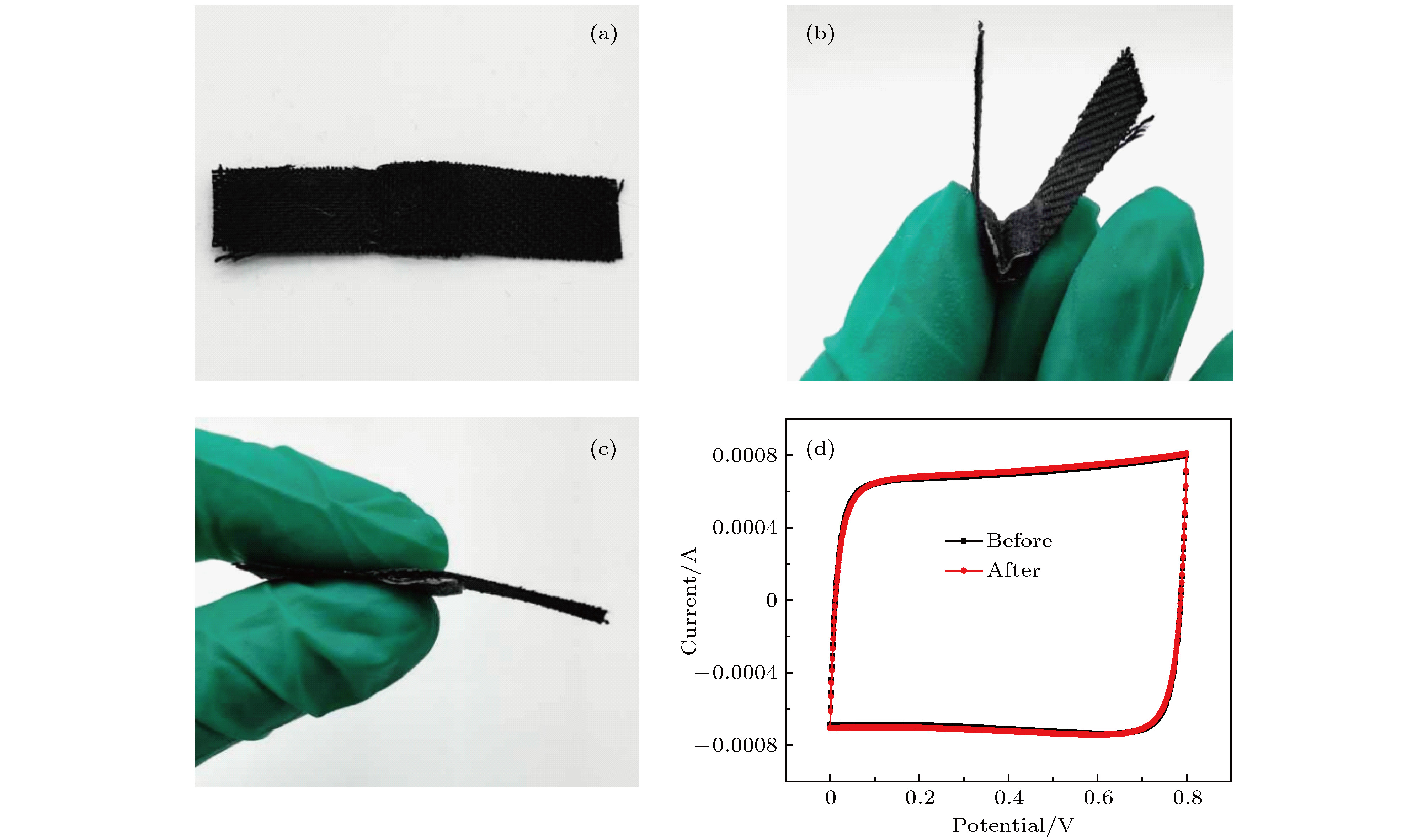
随着科技发展和时代进步, 发展质轻便携、安全环保的高性能储能器件变得日趋重要, 对柔性固态超级电容器的研究也应运而生. 柔性电极材料及电解质的选用是设计柔性固态超级电容器的关键因素, 近年来一直是研究的热点. 考虑到环境污染及实际需求问题, 本文采用中性凝胶电解质对具有高比表面积、良好导电性及取向性的碳纳米管阵列进行包埋处理, 所形成的柔性复合薄膜作为电极材料, 设计制备三明治结构的柔性超级电容器件. 通过改变凝胶电解质中所加入的无机盐电解质种类, 调控器件的电化学储能性质. 最终在聚乙烯醇PVA-NaCl作为凝胶电解质时, 整个器件比容量最高达104.5 mF·cm–3, 远高于有机离子凝胶与碳管阵列形成的复合器件以及无规分布的碳纳米管与水凝胶形成的复合器件, 同时获得了0.034 mW·h·cm–3的最大能量密度, 并且具有良好的倍率性能、循环稳定性及抑制自放电的效果, 并在高电压1.6 V下依然保持良好的化学稳定性. 这种中性凝胶/碳管阵列复合超级电容器件不仅满足了绿色安全、柔性便携的要求, 未来在医学可植入器件等领域也具有很好的应用前景.As a new energy storage device, supercapacitor (or electrochemical capacitor) has an ultra-long cycle life, extremely high power density and enhanced energy density. It fills the gap in the energy-power spectrum between traditional capacitor and battery. In general, the traditional energy storage and conversion device cannot have a perfect trade-off between high energy density and high power density. With the rapid development of modern society, developing light, portable, safe and environmentally friendly high-performance energy storage devices has become increasingly vital. Therefore, there are numerous researches of flexible solid supercapacitors emerging at this historic moment. The selection of flexible electrode materials and that of electrolytes are crucial factors in designing the flexible solid state supercapacitors, which have been the research hotspots in recent years. Carbon nanotube array has been widely used in electrode material of super capacitors due to its excellent electrical conductivity, large specific surface area and super high chemical stability. But in assembly process, carbon nanotube array easily collapses and breaks its neat orientation because of its poor mechanical strength. In consideration of environmental contamination and practical demands, in this paper the neutral gel electrolyte is adopted to embed carbon nanotube array to form flexible composite film electrode. Besides the fact that we use hydrophilic flexible carbon cloth as current collector and neutral gel electrolyte as separator to prepare flexible devices, we compare the electrochemical properties among different devices by changing the electrolyte salt added in gel electrolyte. Meanwhile, after continuous bending and folding, the properties of flexible devices have not been significantly damaged, indicating good flexibility and mechanical stability. The specific capacity of the whole device with PVA-NaCl used as gel electrolyte increases up to 104.5 mF·cm–3, which is much higher than the specific capacity of the composite device formed by organic ionic gels with carbon nanotube array and that of the composite device formed by commercial short carbon nanotubes with hydrogels. A maximum energy density of 0.034 mW·h·cm–3 is obtained at the same time. In addition, it has good rate performance, cycling stability, suppressing self-discharge property, and good chemical stability at a high voltage of 1.6 V. Neutral gel/carbon nanotube array composite devices not only meet the needs of the era of green safety, flexible and portable folding, but also open up the future application prospects of medical implants.
-
Keywords:
- neutral hydrogel /
- carbon nanotube array /
- solid state /
- supercapacitor
[1] Zhang H, Cao G, Yang Y 2009 Energy Environ. Sci. 2 932
 Google Scholar
[2] Zuo W, Li R, Zhou C, Li Y, Xia J, Liu J 2017 Adv. Sci. (Weinheim, Ger. )
4 1600539 [3] He Y, Chen W, Gao C, Zhou J, Li X, Xie E 2013 Nanoscale 5 8799
 Google Scholar
[4] Wei Q, Xiong F, Tan S, Huang L, Lan E H, Dunn B, Mai L 2017 Adv. Mater. 29 1602300
 Google Scholar
[5] Zhi M, Xiang C, Li J, Li M, Wu N 2013 Nanoscale 5 72
 Google Scholar
[6] Keum K, Lee G, Lee H, Yun J, Park H, Hong S Y, Song C, Kim J W, Ha J S 2018 ACS Appl. Mater. Interfaces 10 26248
 Google Scholar
[7] Lu K, Song B, Gao X, Dai H, Zhang J, Ma H 2016 J. Power Sources 303 347
 Google Scholar
[8] Jiang H, Cai X, Qian Y, Zhang C, Zhou L, Liu W, Li B, Lai L, Huang W 2017 J. Mater. Chem. A 5 23727
 Google Scholar
[9] Han Y, Lu Y, Shen S, Zhong Y, Liu S, Xia X, Tong Y, Lu X 2018 Adv. Funct. Mater. 29 1806329
[10] Sun P, Qiu M, Li M, Mai W, Cui G, Tong Y 2019 Nano Energy 55 506
 Google Scholar
[11] Yao B, Zhang J, Kou T, Song Y, Liu T, Li Y 2017 Adv. Sci. (Weinheim, Ger. )
4 1700107 [12] Xiao X, Peng X, Jin H, Li T, Zhang C, Gao B, Hu B, Huo K, Zhou J 2013 Adv. Mater. 25 5091
 Google Scholar
[13] Yang P, Mai W 2014 Nano Energy 8 274
 Google Scholar
[14] Yoo J J, Balakrishnan K, Huang J, Meunier V, Sumpter B G, Srivastava A, Conway M, Reddy A L, Yu J, Vajtai R, Ajayan P M 2011 Nano Lett. 11 1423
 Google Scholar
[15] Zhang L L, Zhao X S 2009 Chem. Soc. Rev. 38 2520
 Google Scholar
[16] Meng C, Liu C, Chen L, Hu C, Fan S 2010 Nano Lett. 10 4025
 Google Scholar
[17] Chen Q, Li X, Zang X, Cao Y, He Y, Li P, Wang K, Wei J, Wu D, Zhu H 2014 RSC Adv. 4 36253
 Google Scholar
[18] Lota G, Fic K, Frackowiak E 2011 Energy Environ. Sci. 4 1592
 Google Scholar
[19] Batisse N, Raymundo-Piñero E 2017 J. Power Sources 348 168
 Google Scholar
[20] Wang G, Lu X, Ling Y, Zhai T, Wang H, Tong Y, Li Y 2012 ACS Nano 6 10296
 Google Scholar
[21] Kim D, Yun J, Lee G, Ha J S 2014 Nanoscale 6 12034
 Google Scholar
[22] Yang P, Xiao X, Li Y, Ding Y, Qiang P, Tan X, Mai W, Lin Z, Wu W, Li T 2013 ACS Nano 7 2617
 Google Scholar
[23] Wei W, Cui X, Chen W, Ivey D G 2011 Chem. Soc. Rev. 40 1697
 Google Scholar
[24] Balamurugan J, Li C, Thanh T D, Park O K, Kim N H, Lee J H 2017 J. Mater. Chem. A 5 19760
 Google Scholar
[25] Hsia B, Marschewski J, Wang S, In J B, Carraro C, Poulikakos D, Grigoropoulos C P, Maboudian R 2014 Nanotechnology 25 055401
 Google Scholar
[26] Kang Y J, Chung H, Han C H, Kim W 2012 Nanotechnology 23 289501
 Google Scholar
[27] Wang G, Zhang L, Zhang J 2012 Chem. Soc. Rev. 41 797
 Google Scholar
[28] Zhang X, Deng S, Zeng Y, Yu M, Zhong Y, Xia X, Tong Y, Lu X 2018 Adv. Funct. Mater. 28 1805618
 Google Scholar
[29] 朱畦, 袁协涛, 诸翊豪, 张晓华, 杨朝晖 2018 67 028201
 Google Scholar
Zhu Q, Yuan X T, Zhu Y H, Zhang X H, Yang Z H 2018 Acta Phys. Sin. 67 028201
 Google Scholar
[30] Zhu Q, Yuan X, Zhu Y, Ni J, Zhang X, Yang Z 2018 Nanotechnology 29 195405
 Google Scholar
[31] Evanko B, Boettcher S W, Yoo S J, Stucky G D 2017 ACS Energy Lett. 2 2581
 Google Scholar
-
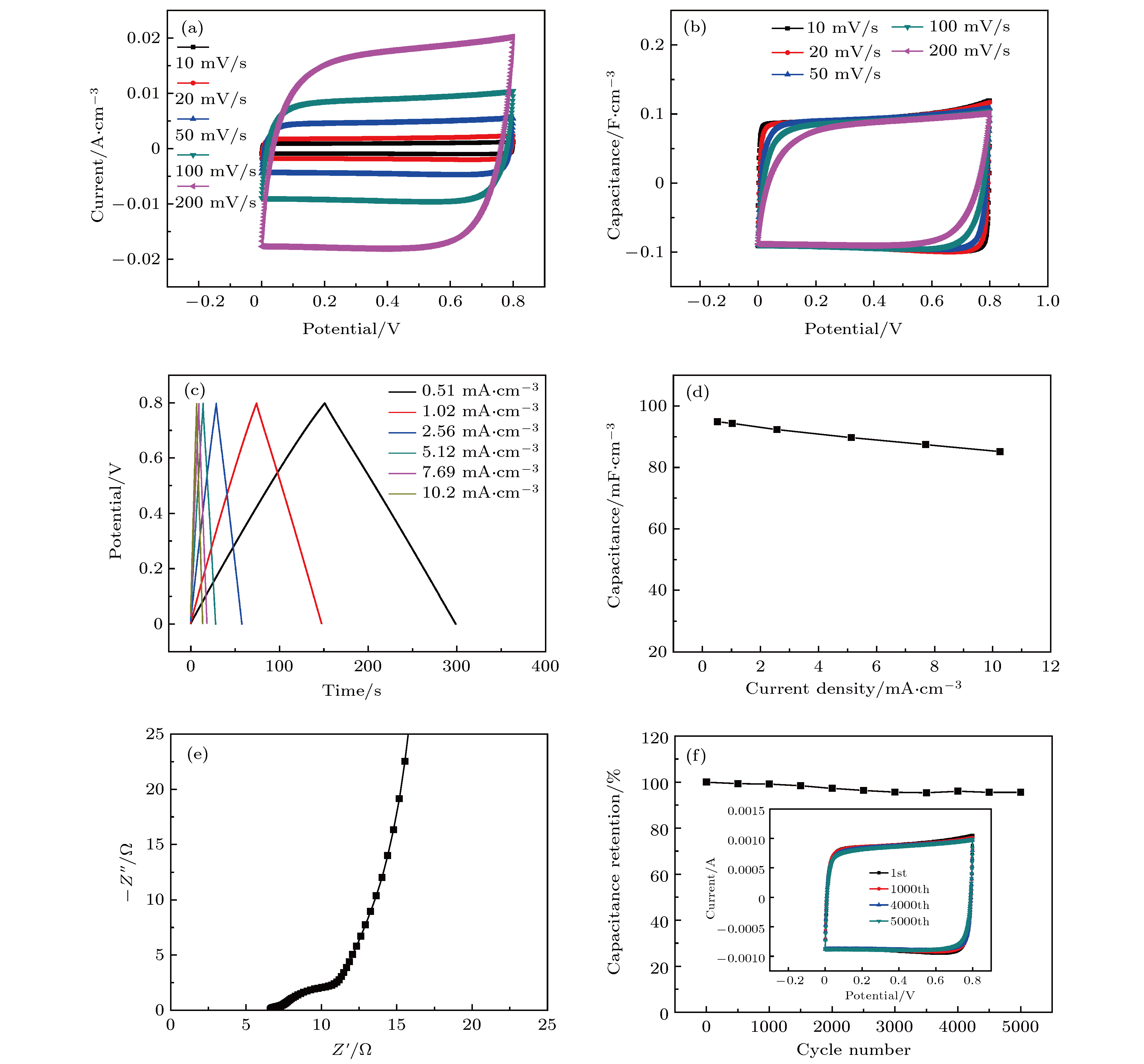
图 3 PVA-CH3COONa/CNTA复合器件的电化学性能测试 (a) 10−200 mV/s扫速下循环伏安曲线(CV); (b)不同扫速下的瞬时电容图; (c) 0.51−10.2 mA·cm–3不同电流密度下的恒流充放电曲线(GCD); (d)比电容随电流密度变化图; (e) 0.01−100k Hz频率下器件EIS; (f)5000次循环充放电下器件稳定图
Fig. 3. Electrochemical performance test of PVA-CH3COONa/CNTA composite device: (a) CV curves at different scan rates ranging from 10 to 200 mV/s; (b) instantaneous capacitance diagram at different scan rates; (c) galvanostatic charge-discharge (GCD) curves at different current densities (0.51–10.2 mA·cm–3); (d) evolution of specific capacitance versus current density; (e) Nyquist plot of the device at a frequency range from 0.01 to 100k Hz; (f) cyclic stability of the device during 5000 charging-discharging cycles.
图 5 (a) 50 mV/s扫速下CV对比图; (b) 5.1 mA·cm–3电流密度下GCD对比图; (c) EIS对比图; (d)能量-功率密度对比图; (e) 5000次循环稳定性对比图
Fig. 5. Comparison of electrochemical properties of different neutral gel/CNTA composite devices: (a) CV comparison diagram at 50 mV/s scan rate; (b) GCD comparison diagram at 5.1 mA·cm–3 current density; (c) EIS Nyquist plots obtained from the electrochemical impedance test for different samples; (d) Ragone plots of the different samples; (e) the cyclic performances of the different samples for 5000 cycles.
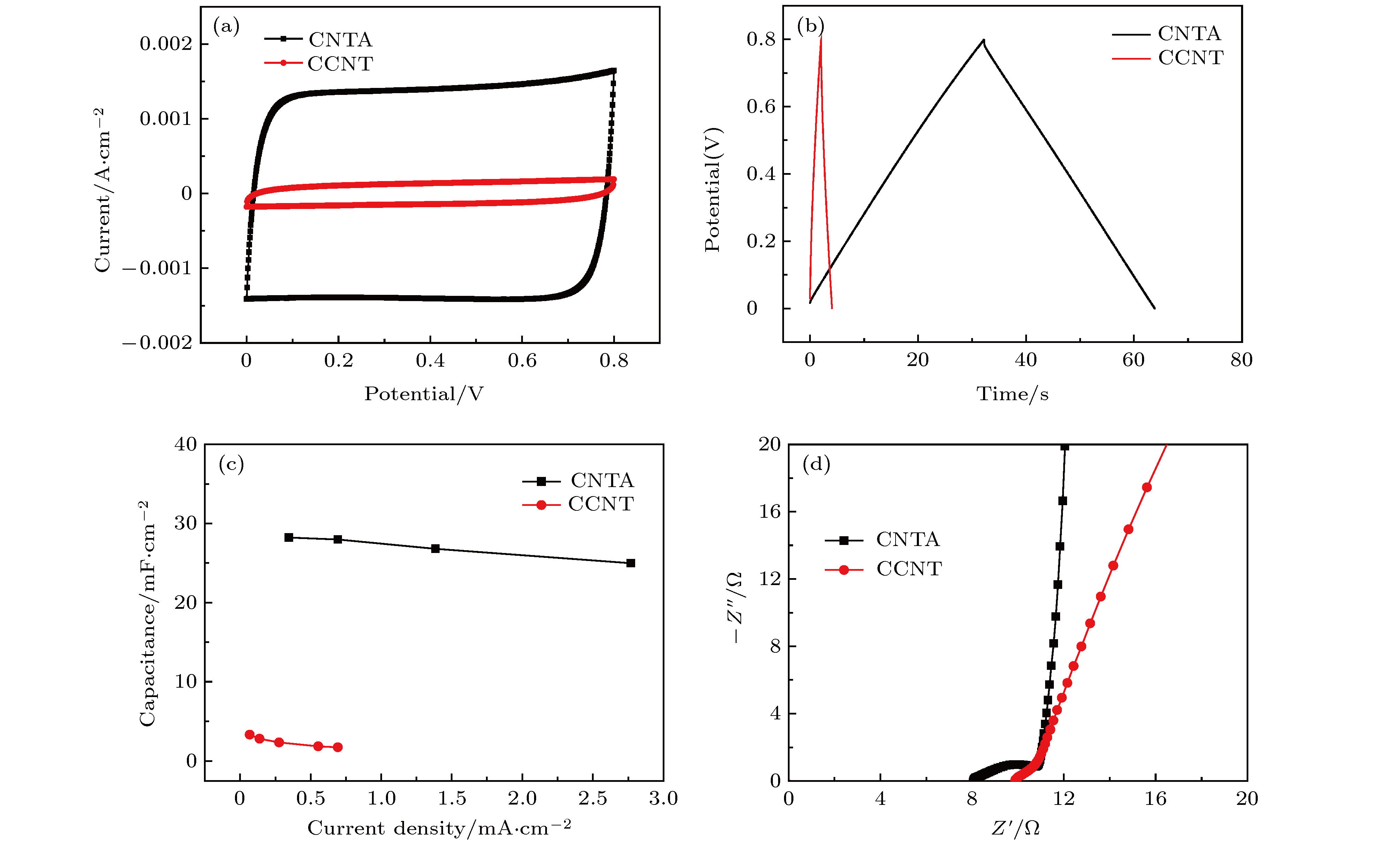
图 6 PVA-NaCl/CNTA和PVA-NaCl/CCNT复合器件的电化学性能测试对比 (a) 50 mV/s扫速下CV对比图; (b) 0.69 mA·cm–2电流密度下GCD对比图; (c)比电容随电流密度变化图; (d)高频下EIS对比图
Fig. 6. Comparison of electrochemical properties of PVA-NaCl/CNTA and PVA-NaCl/CCNT composite devices: (a) CV comparison diagram at 50 mV/s scan rate; (b) GCD comparison diagram at 0.69 mA·cm–2 current density; (c) diagram of specific capacitance changing with current density; (d) EIS comparison diagram at high frequency.
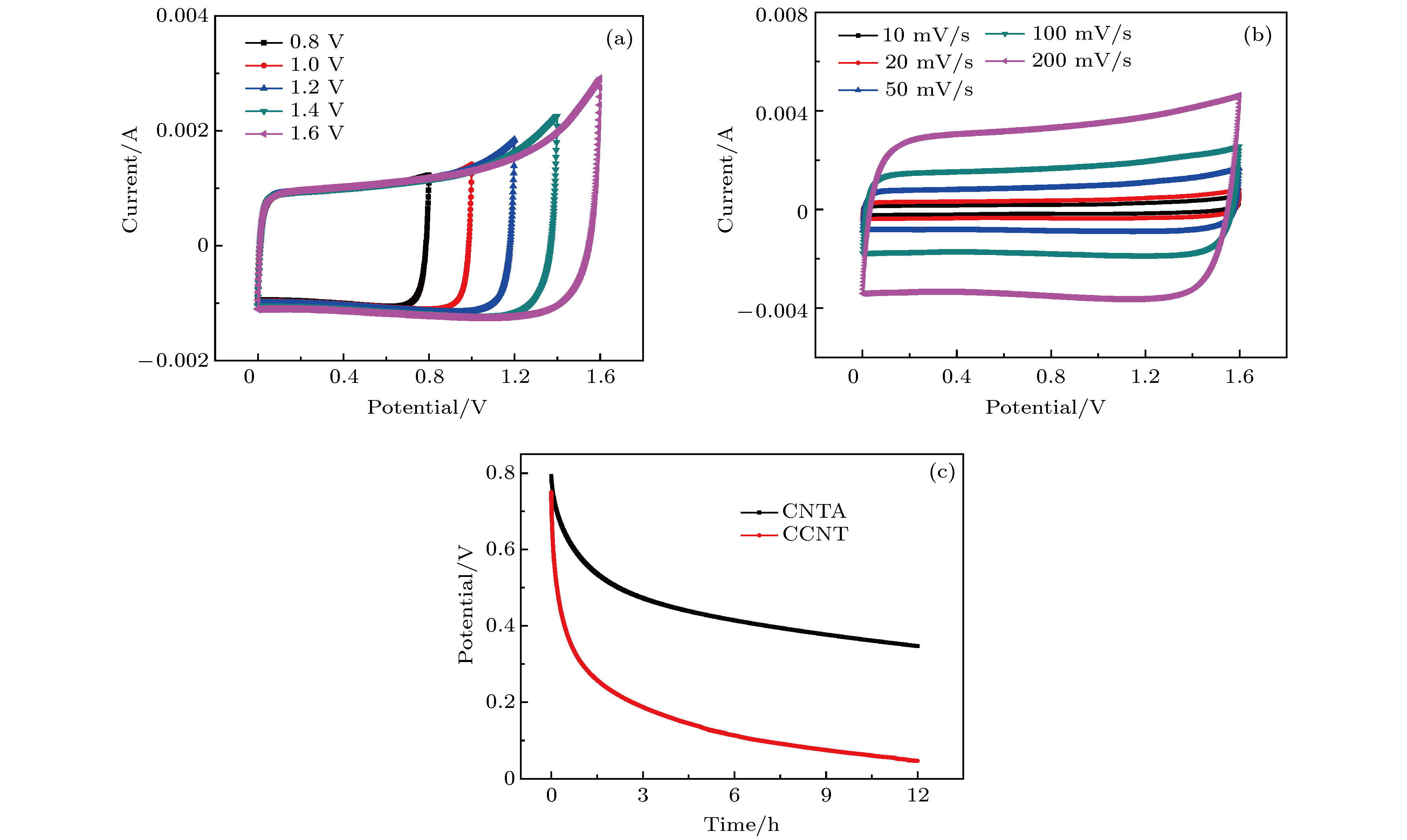
图 7 PVA-NaCl/CNTA复合器件的电化学性能测试 (a) 50 mV/s扫速下0.8−1.6 V不同电压范围内CV曲线图; (b) 10−200 mV/s扫速下高电位CV曲线图; (c) 分别基于取向阵列和碳管粉末的器件自放电对比图
Fig. 7. Electrochemical performance test of PVA-NaCl/CNTA composite device: (a) CV curves in different voltages ranging from 0.8 to 1.6 V at 50 mV/s scan rate; (b) high-potential CV curves over the scan rates ranging from 10 to 200 mV/s; (c) self-discharge comparison diagram based on CNTA and CCNT respectively.
-
[1] Zhang H, Cao G, Yang Y 2009 Energy Environ. Sci. 2 932
 Google Scholar
[2] Zuo W, Li R, Zhou C, Li Y, Xia J, Liu J 2017 Adv. Sci. (Weinheim, Ger. )
4 1600539 [3] He Y, Chen W, Gao C, Zhou J, Li X, Xie E 2013 Nanoscale 5 8799
 Google Scholar
[4] Wei Q, Xiong F, Tan S, Huang L, Lan E H, Dunn B, Mai L 2017 Adv. Mater. 29 1602300
 Google Scholar
[5] Zhi M, Xiang C, Li J, Li M, Wu N 2013 Nanoscale 5 72
 Google Scholar
[6] Keum K, Lee G, Lee H, Yun J, Park H, Hong S Y, Song C, Kim J W, Ha J S 2018 ACS Appl. Mater. Interfaces 10 26248
 Google Scholar
[7] Lu K, Song B, Gao X, Dai H, Zhang J, Ma H 2016 J. Power Sources 303 347
 Google Scholar
[8] Jiang H, Cai X, Qian Y, Zhang C, Zhou L, Liu W, Li B, Lai L, Huang W 2017 J. Mater. Chem. A 5 23727
 Google Scholar
[9] Han Y, Lu Y, Shen S, Zhong Y, Liu S, Xia X, Tong Y, Lu X 2018 Adv. Funct. Mater. 29 1806329
[10] Sun P, Qiu M, Li M, Mai W, Cui G, Tong Y 2019 Nano Energy 55 506
 Google Scholar
[11] Yao B, Zhang J, Kou T, Song Y, Liu T, Li Y 2017 Adv. Sci. (Weinheim, Ger. )
4 1700107 [12] Xiao X, Peng X, Jin H, Li T, Zhang C, Gao B, Hu B, Huo K, Zhou J 2013 Adv. Mater. 25 5091
 Google Scholar
[13] Yang P, Mai W 2014 Nano Energy 8 274
 Google Scholar
[14] Yoo J J, Balakrishnan K, Huang J, Meunier V, Sumpter B G, Srivastava A, Conway M, Reddy A L, Yu J, Vajtai R, Ajayan P M 2011 Nano Lett. 11 1423
 Google Scholar
[15] Zhang L L, Zhao X S 2009 Chem. Soc. Rev. 38 2520
 Google Scholar
[16] Meng C, Liu C, Chen L, Hu C, Fan S 2010 Nano Lett. 10 4025
 Google Scholar
[17] Chen Q, Li X, Zang X, Cao Y, He Y, Li P, Wang K, Wei J, Wu D, Zhu H 2014 RSC Adv. 4 36253
 Google Scholar
[18] Lota G, Fic K, Frackowiak E 2011 Energy Environ. Sci. 4 1592
 Google Scholar
[19] Batisse N, Raymundo-Piñero E 2017 J. Power Sources 348 168
 Google Scholar
[20] Wang G, Lu X, Ling Y, Zhai T, Wang H, Tong Y, Li Y 2012 ACS Nano 6 10296
 Google Scholar
[21] Kim D, Yun J, Lee G, Ha J S 2014 Nanoscale 6 12034
 Google Scholar
[22] Yang P, Xiao X, Li Y, Ding Y, Qiang P, Tan X, Mai W, Lin Z, Wu W, Li T 2013 ACS Nano 7 2617
 Google Scholar
[23] Wei W, Cui X, Chen W, Ivey D G 2011 Chem. Soc. Rev. 40 1697
 Google Scholar
[24] Balamurugan J, Li C, Thanh T D, Park O K, Kim N H, Lee J H 2017 J. Mater. Chem. A 5 19760
 Google Scholar
[25] Hsia B, Marschewski J, Wang S, In J B, Carraro C, Poulikakos D, Grigoropoulos C P, Maboudian R 2014 Nanotechnology 25 055401
 Google Scholar
[26] Kang Y J, Chung H, Han C H, Kim W 2012 Nanotechnology 23 289501
 Google Scholar
[27] Wang G, Zhang L, Zhang J 2012 Chem. Soc. Rev. 41 797
 Google Scholar
[28] Zhang X, Deng S, Zeng Y, Yu M, Zhong Y, Xia X, Tong Y, Lu X 2018 Adv. Funct. Mater. 28 1805618
 Google Scholar
[29] 朱畦, 袁协涛, 诸翊豪, 张晓华, 杨朝晖 2018 67 028201
 Google Scholar
Zhu Q, Yuan X T, Zhu Y H, Zhang X H, Yang Z H 2018 Acta Phys. Sin. 67 028201
 Google Scholar
[30] Zhu Q, Yuan X, Zhu Y, Ni J, Zhang X, Yang Z 2018 Nanotechnology 29 195405
 Google Scholar
[31] Evanko B, Boettcher S W, Yoo S J, Stucky G D 2017 ACS Energy Lett. 2 2581
 Google Scholar
计量
- 文章访问数: 13217
- PDF下载量: 140
- 被引次数: 0


 下载:
下载:


