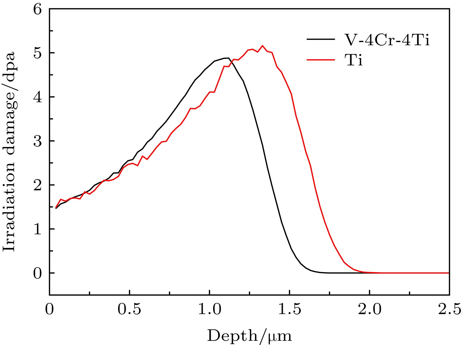
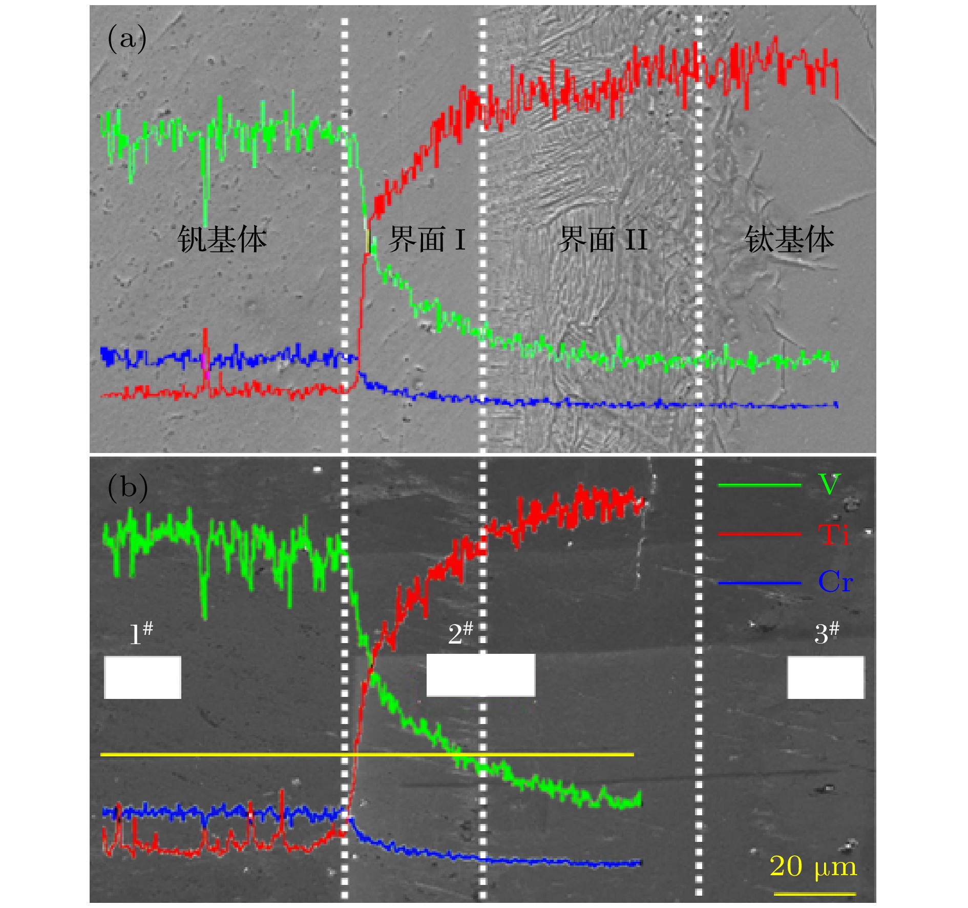
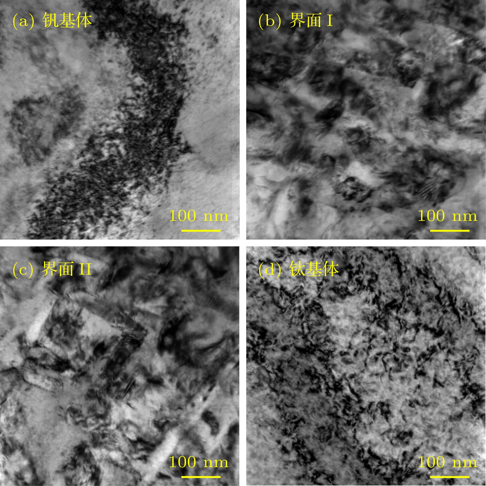
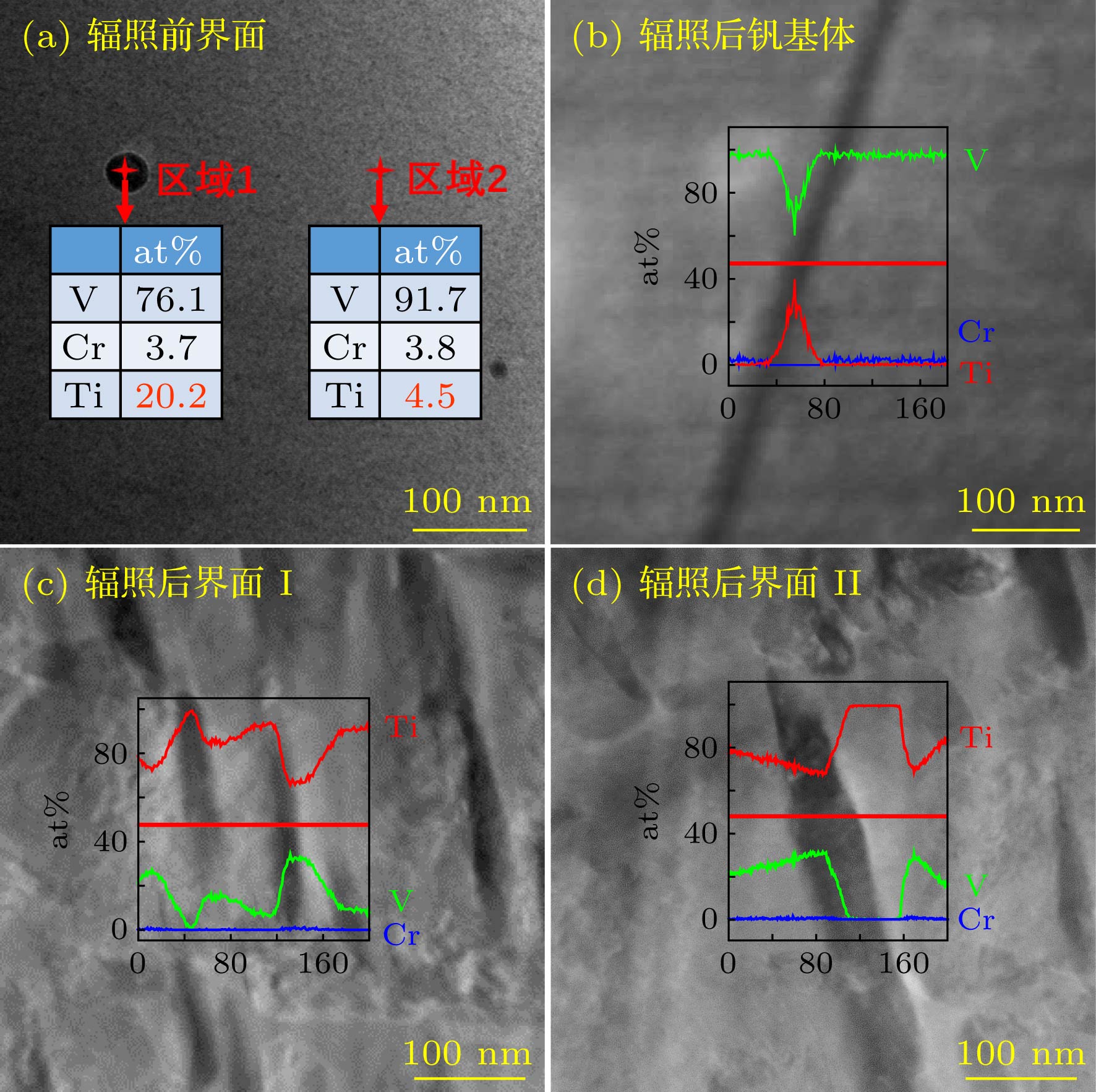
-
采用透射电子显微镜和纳米压痕技术研究了高能Fe10+离子注入后V-4Cr-4Ti/Ti复合材料界面辐照硬化、辐照缺陷以及微观结构的变化. 根据样品成分和微观结构的特征, 将该复合材料分成V-4Cr-4Ti基体、界面I、界面II和Ti基体四个区域. 纳米压痕结果表明, 辐照后样品均发生了辐照硬化, 但界面处的辐照硬化远低于两基体, 说明异质材料界面表现出了良好的抗辐照硬化能力. 透射电子显微镜结果表明, 辐照后界面处的辐照缺陷密度较小、尺寸较大、分布较均匀; 而在两基体中辐照缺陷密度大、尺寸小且大量缠结. 辐照后V-4Cr-4Ti基体、界面I区和界面II区均有一些富Ti析出物, 但界面I的析出物数量和尺寸均高于界面II和V-4Cr-4Ti基体. 由于Ti的析出改变了样品中局部的V/Ti比, 导致界面I部分区域由β-Ti转变为α-Ti, 形成α + β Ti共存区.
-
关键词:
- V-4Cr-4Ti/Ti /
- 异质材料界面 /
- 析出物 /
- 辐照缺陷
The development of electrically insulating coatings is extremely important for the lithium/vanadium (Li/V) blanket of the fusion reactor. However, Li/V cladding materials suffer many problems such as tritiumpermeation and material corrosion. Thus, it is very important to find suitable insulating, tritium-resistant and corrosion-resistant coatings. So, the " V-alloy/Ti/AlN” bilayer coating was proposed by our group in previous study for the first time. In this paper, the evolution of the hardness, irradiation defects and microstructure of the Ti-clad V-4Cr-4Ti composite material after Fe10+ implantation are studied by transmission electron microscopy (TEM) and nanoindentation. According to the characteristics of the composition and microstructure, V-4Cr-4Ti/Ti composite material can be divided into four zones: V-4Cr-4Ti matrix, interface I (the interface near V-4Cr-4Ti matrix), interface II (the interface near Ti matrix), and Ti matrix. The nanoindentation results show that radiation hardening occurs in all regions during irradiation. The radiation hardening in the interface is lower than in the V-4Cr-4Ti and Ti matrix. Thus, the interface of heterogeneous material exhibits fine resistance to radiation hardening. The experimental values of hardness are much higher than the values calculated by the dispersed barrier hardening model. One reason for the discrepancy is that the theoretical values are calculated under the hypothesis of the uniform loop distribution. Actually, a large number of dislocation loops accumulate and tangle with each other in the samples. In addition, the formation of the precipitates is also one of the key factors. The TEM results show that the irradiation defects in the interface are low in density, large in size, and uniform in distribution. As a contrast, high density, small size and twisted dislocation loops are observed in irradiated V-4Cr-4Ti and Ti matrix. These results indicate that the interface can play a critical role in the resistance to irradiation damage. Few tiny Ti-rich precipitates appear in the V-4Cr-4Ti matrix, while there are large quantities of Ti precipitates in the interface after irradiation. Moreover, the number and size of precipitates in the interface I are larger than those in the interface II due to the formation of a few V-rich precipitates in the interface I. The formation of precipitations changes the proportion of V/Ti, which leads to the transformation from β-Ti to α-Ti in the interface.[1] 张高伟, 韩文妥, 崔丽娟, 万发荣 2018 稀有金属材料与工程 5 1537
Zhang G W, Han W T, Cui L J, Wan F R 2018 Rare Metal Mat. Eng. 5 1537
[2] Zhang G W, Han W T, Yi X O, Wan F R 2018 Appl. Sci. 8 577
 Google Scholar
[3] Gohar Y, Majumdar S, Smith D L 2000 Fusion Eng. Des. 49 551
[4] Smith D L, Billone M C, Natesan K 2000 Int. J. Refract. Met. H 18 213
 Google Scholar
[5] Jones R H, Heinisch H L, McCarthy K A 1999 J. Nucl. Mater. 271 518
[6] Kirillov I R, Danilov I V, Sidorenkov S I, Strebkov Y S, Mattas R F, Gohar Y, Hua T Q, Smith D L 1998 Fusion Eng. Des. 39 669
[7] Mattas R F, Smith D L, Reed C D, Parka J H, Kirillov I R, Strebkov Y S, Rusanov A E, Votinov S N 1998 Fusion Eng. Des. 39 659
[8] Muroga T 2005 Mater. Trans. 46 405
 Google Scholar
[9] Malang S, Bühler L 1994 MHD Pressure Drop in Ducts with Imperfectly Insulating Coatings (Chicago: Argonne National Laboratory Report) Report No. ANL/FPP/TM-269
[10] Vertkov A V, Evtikhin V A, Lyublinski I E 2001 Fusion Eng. Des. 58 731
[11] Smith D L, Konys J, Muroga T, Evitkhin V 2002 J. Nucl. Mater. 307 1314
[12] Muroga T, Pint B A 2010 Fusion Eng. Des. 85 1301
 Google Scholar
[13] Wang J, Li Q, Xiang Q Y, Cao J L 2016 Fusion Eng. Des. 102 94
 Google Scholar
[14] Suzuki A, Muroga T, Pint B A, Yoneoka T, Tanaka S 2003 Fusion Eng. Des. 69 397
 Google Scholar
[15] Pint B A, DeVan J H, DiStefano J R 2002 J. Nucl. Mater. 307 1344
[16] Pint B A, Tortorelli P F, JankowskiA, Hayes J, Muroga T, Suzuki A, Yeliseyeva O I, Chernov V M 2004 J. Nucl. Mater. 329 119
[17] Jiří M, Pavel C 2010 Adv. Sci. Technol. 66 19
[18] Vitkovsky I V, Gorunov A V, Kirillov I R, Khoroshikh V M, Kraev V D, Ogorodnikov A P, Petrovsky V Y, Rusanov A E 2002 Fusion Eng. Des. 61 739
[19] Demkowicz M J, Hoagland R G, Hirth J P 2008 Phys. Rev. Lett. 100 136102
 Google Scholar
[20] Kolluri K, Demkowicz M J 2012 Phys. Rev. B 85 205416
 Google Scholar
[21] Stoller R E, Toloczko M B, Was G S, Certain A G, Dwaraknath S, Garner F A 2013 Nucl. Instrum. Meth. B 310 75
 Google Scholar
[22] ASTM Committee E521–96 2003 Standard Practice for Neutron Radiation Damage Simulation by Charged-Particle Irradiation (vol.12.02) (West Conshohocken: Copyright © ASTM International) p8
[23] 万发荣 1993 金属材料的辐照损伤 (北京: 科学出版社) 第143页
Wan F R 1993 Irradiation Damage of Metal Materials (Vol. 1) (Beijing: Science Press) p143 (in Chinese)
[24] Fu E G, Carter J, Swadener G, Misra A, Shao L, Wang H, Zhang X 2009 J. Nucl. Mater. 385 629
 Google Scholar
[25] Watanabe H, Nagamine M, Yamasaki K, Yoshida N, Heo N J, Nagasaka T, Muroga T 2005 Mater. Sci. Forum 475 1491
[26] Heo N J, Nagasaka T, Muroga T, Nishimura A, Shinozaki K, Watanabe H 2003 Fusion Sci. Technol. 44 470
 Google Scholar
[27] Han W Z, Demkowicz M J, Fu E G, Wang Y Q, Misra A 2012 Acta Mater. 60 6341
 Google Scholar
[28] Zhang Y F, Zhan Q, Ohnuki S, Kimura A, Wan F R, Yoshida K, Nagai Y 2019 J. Nucl. Mater. 517 1
 Google Scholar
[29] Bergner F, Pareige C, Hernández-Mayoral M, Malerba L, Heintze C 2014 J. Nucl. Mater. 448 96
 Google Scholar
[30] 张高伟 2018 博士学位论文 (北京: 北京科技大学)
Zhang G W 2018 Ph. D. Dissertation (Beijing: University of Science and Technology Beijing) (in Chinese)
-
表 1 通过纳米压痕所得硬化实验值与采用DBH模型对辐照硬化进行的估算值
Table 1. Experimental hardness values by nanoindentation and the estimated hardness values calculated by the DBH model
钒基体 界面I 界面II 钛基体 ΔHV实验值 207 136 55 247 N/m–3 1.5 × 10²² 8.0 × 10²¹ 8.4 × 10²¹ 1.3 × 10²² d/nm 7.3 ± 1.5 19.9 ± 5.0 20.3 ± 4.8 11.2 ± 2.0 N·d 1.09 × 10¹⁴ 1.59 × 10¹⁴ 1.70 × 10¹⁴ 1.46 × 10¹⁴ $ \sqrt {N\cdot d} $ 1.05 × 10⁷ 1.26 × 10⁷ 1.31 × 10⁷ 1.21 × 10⁷ ΔHV计算值 39.5 27.7 38.6* 44.8 注: *表示界面II处α + β Ti区的硬化按α-Ti和β-Ti各占50%进行计算. -
[1] 张高伟, 韩文妥, 崔丽娟, 万发荣 2018 稀有金属材料与工程 5 1537
Zhang G W, Han W T, Cui L J, Wan F R 2018 Rare Metal Mat. Eng. 5 1537
[2] Zhang G W, Han W T, Yi X O, Wan F R 2018 Appl. Sci. 8 577
 Google Scholar
[3] Gohar Y, Majumdar S, Smith D L 2000 Fusion Eng. Des. 49 551
[4] Smith D L, Billone M C, Natesan K 2000 Int. J. Refract. Met. H 18 213
 Google Scholar
[5] Jones R H, Heinisch H L, McCarthy K A 1999 J. Nucl. Mater. 271 518
[6] Kirillov I R, Danilov I V, Sidorenkov S I, Strebkov Y S, Mattas R F, Gohar Y, Hua T Q, Smith D L 1998 Fusion Eng. Des. 39 669
[7] Mattas R F, Smith D L, Reed C D, Parka J H, Kirillov I R, Strebkov Y S, Rusanov A E, Votinov S N 1998 Fusion Eng. Des. 39 659
[8] Muroga T 2005 Mater. Trans. 46 405
 Google Scholar
[9] Malang S, Bühler L 1994 MHD Pressure Drop in Ducts with Imperfectly Insulating Coatings (Chicago: Argonne National Laboratory Report) Report No. ANL/FPP/TM-269
[10] Vertkov A V, Evtikhin V A, Lyublinski I E 2001 Fusion Eng. Des. 58 731
[11] Smith D L, Konys J, Muroga T, Evitkhin V 2002 J. Nucl. Mater. 307 1314
[12] Muroga T, Pint B A 2010 Fusion Eng. Des. 85 1301
 Google Scholar
[13] Wang J, Li Q, Xiang Q Y, Cao J L 2016 Fusion Eng. Des. 102 94
 Google Scholar
[14] Suzuki A, Muroga T, Pint B A, Yoneoka T, Tanaka S 2003 Fusion Eng. Des. 69 397
 Google Scholar
[15] Pint B A, DeVan J H, DiStefano J R 2002 J. Nucl. Mater. 307 1344
[16] Pint B A, Tortorelli P F, JankowskiA, Hayes J, Muroga T, Suzuki A, Yeliseyeva O I, Chernov V M 2004 J. Nucl. Mater. 329 119
[17] Jiří M, Pavel C 2010 Adv. Sci. Technol. 66 19
[18] Vitkovsky I V, Gorunov A V, Kirillov I R, Khoroshikh V M, Kraev V D, Ogorodnikov A P, Petrovsky V Y, Rusanov A E 2002 Fusion Eng. Des. 61 739
[19] Demkowicz M J, Hoagland R G, Hirth J P 2008 Phys. Rev. Lett. 100 136102
 Google Scholar
[20] Kolluri K, Demkowicz M J 2012 Phys. Rev. B 85 205416
 Google Scholar
[21] Stoller R E, Toloczko M B, Was G S, Certain A G, Dwaraknath S, Garner F A 2013 Nucl. Instrum. Meth. B 310 75
 Google Scholar
[22] ASTM Committee E521–96 2003 Standard Practice for Neutron Radiation Damage Simulation by Charged-Particle Irradiation (vol.12.02) (West Conshohocken: Copyright © ASTM International) p8
[23] 万发荣 1993 金属材料的辐照损伤 (北京: 科学出版社) 第143页
Wan F R 1993 Irradiation Damage of Metal Materials (Vol. 1) (Beijing: Science Press) p143 (in Chinese)
[24] Fu E G, Carter J, Swadener G, Misra A, Shao L, Wang H, Zhang X 2009 J. Nucl. Mater. 385 629
 Google Scholar
[25] Watanabe H, Nagamine M, Yamasaki K, Yoshida N, Heo N J, Nagasaka T, Muroga T 2005 Mater. Sci. Forum 475 1491
[26] Heo N J, Nagasaka T, Muroga T, Nishimura A, Shinozaki K, Watanabe H 2003 Fusion Sci. Technol. 44 470
 Google Scholar
[27] Han W Z, Demkowicz M J, Fu E G, Wang Y Q, Misra A 2012 Acta Mater. 60 6341
 Google Scholar
[28] Zhang Y F, Zhan Q, Ohnuki S, Kimura A, Wan F R, Yoshida K, Nagai Y 2019 J. Nucl. Mater. 517 1
 Google Scholar
[29] Bergner F, Pareige C, Hernández-Mayoral M, Malerba L, Heintze C 2014 J. Nucl. Mater. 448 96
 Google Scholar
[30] 张高伟 2018 博士学位论文 (北京: 北京科技大学)
Zhang G W 2018 Ph. D. Dissertation (Beijing: University of Science and Technology Beijing) (in Chinese)
计量
- 文章访问数: 9417
- PDF下载量: 80
- 被引次数: 0


 下载:
下载:


