-
The epitaxial orientation of YBa2Cu3O7–δ grown via the oxygen partial pressure jump pathway in transient liquid-phase assisted chemical solution deposition (TLAG-CSD) depends on the barium-to-copper ratio in the precursor phase. To explore the mechanism behind this phenomenon, in this work we investigate the effects of different oxygen partial pressures and barium-to-copper ratio components on the barium-copper-oxygen liquid phase ([Ba-Cu-O]L) and the intermediate phase transition in the medium-high temperature heat treatment process. The research shows that the formation of the liquid phase exhibits a point-to-surface characteristic; the temperature and morphological differences in the liquid phase are mainly determined by the composition, with oxygen partial pressure only playing a supporting role. Y∶Ba∶Cu = 0∶3∶7 (0-3-7) components all appear before Y∶Ba∶Cu = 0∶2∶3 (0-2-3) components in the liquid phase, with a temperature difference of 20 ℃ (high oxygen partial pressure) or 40 ℃ (low oxygen partial pressure). Experimental results indicate that there are differences in the intermediate phase properties between these two components. Under high oxygen partial pressure, the intermediate phase BaCuO2 exhibits a single characteristic peak in the 0-3-7 component, with large and dispersed grains; the 0-2-3 component has multiple characteristic peaks, with small and dense grains. The surface area of the liquid phase region in the 0-3-7 component is smaller than that in the 0-2-3 component, resulting in different supersaturation levels of Y3+ in the liquid phases of the two components and causing orientation differences in YBCO. Finally, the basic model for the formation of fluorine-free liquid phase is summarized, and the complete [Ba-Cu-O]L film can be generated from the 0-2-3 component at high oxygen partial pressure and 750 ℃.
-
Keywords:
- transientliquid-phase assisted chemical solution deposition /
- epitaxial orientation of YBa2Cu3O7–δ /
- [Ba-Cu-O]L /
- barium copper ratio
[1] Zhou Y H, Park D, Iwasa Y 2023 Natl. Sci. Rev. 10 nwad001
 Google Scholar
[2] Obradors X, Puig T 2014 Supercond. Sci. Technol. 27 044003
 Google Scholar
[3] Barth C, Komorowski P, Vonlanthen P, Herzog R, Tediosi R, Alessandrini M, Bonura M, Senatore C 2019 Supercond. Sci. Technol. 32 075005
 Google Scholar
[4] Chow C C T, Ainslie M D, Chau K T 2023 Energy Rep. 9 1124
 Google Scholar
[5] Favre S, Ariosa D, Yelpo C, Mazini M, Faccio R 2021 Mater. Chem. Phys. 266 124507
 Google Scholar
[6] Khan M Z, Rivasto E, Tikkanen J, Rijckaert H, Malmivirta M, Liedke M O, Butterling M, Wagner A, Huhtinen H, Van Driessche I, Paturi P 2019 Sci. Rep. 9 15425
 Google Scholar
[7] Yang T W, Wang L M 2023 IEEE Trans. Appl. Supercond. 33 1
 Google Scholar
[8] Chen X, Tao B, Zhao R, Yang K, Li Z, Xie T, Zhong Y, Zhang T, Xia Y 2023 Mater. Lett. 330 133336
 Google Scholar
[9] Chen T Y, Xia Y D, Zhao R P, Wu D, Feng Z P, Yang J T, Xin J J, Wang W, Jin K, Tao B W 2022 Ceram. Int. 48 17837
 Google Scholar
[10] Zhao P, Wang Y, Huang Z L, Mao Y, Xu Y L 2015 J. Cryst. Growth 415 152
 Google Scholar
[11] Jin L H, Bai Y, Li C S, Feng J Q, Lei L, Zhao G Y, Gao L, Zhang P X 2019 Mater. Lett. 250 34
 Google Scholar
[12] Wesolowski D E, Patta Y R, Cima M J 2009 Phys. C Supercond. 469 766
 Google Scholar
[13] Bhuiyan M S, Paranthaman M, Salama K 2006 Supercond. Sci. Technol. 19 R1
 Google Scholar
[14] Chu J Y, Zhao Y, Khan M Z, Tang X, Wu W, Shi J T, Wu Y, Huhtinen H, Suo H L, Jin Z J 2019 Cryst. Growth Des. 19 6752
 Google Scholar
[15] Soler L, Jareño J, Banchewski J, Rasi S, Chamorro N, Guzman R, Yáñez R, Mocuta C, Ricart S, Farjas J, Roura-Grabulosa P, Obradors X, Puig T 2020 Nat. Commun. 11 344
 Google Scholar
[16] Shi J T, Zhao Y, Jiang G Y, Zhu J M, Wu Y, Gao Y S, Quan X L, Yu X, Wu W, Jin Z J 2021 J. Eur. Ceram. Soc. 41 5223
 Google Scholar
[17] Chu J Y, Zhao Y, Ji Y T, Wu W, Shi J T, Hong Z Y, Ma L, Suo H L, Jin Z J 2019 J. Am. Ceram. Soc. 102 5705
 Google Scholar
[18] Chu N, Liu Z Y, Yang Z, Tong S, Shen J, Chen J, Cai C B 2022 Jpn. J. Appl. Phys. 61 075509
 Google Scholar
[19] Shen J J, Liu Z Y, Chen J, Zhou X H, Li Y G, Cai C B 2022 J. Supercond. Nov. Magn. 35 3147
 Google Scholar
[20] Saltarelli L, Gupta K, Rasi S, Kethamkuzhi A, Queraltó A, Garcia D, Gutierrez J, Farjas J, Roura-Grabulosa P, Ricart S, Obradors X, Puig T 2022 ACS Appl. Mater. Interfaces 14 48582
 Google Scholar
[21] Rasi S, Queraltó A, Banchewski J, Saltarelli L, Garcia D, Pacheco A, Gupta K, Kethamkuzhi A, Soler L, Jareño J, Ricart S, Farjas J, Roura-Grabulosa P, Mocuta C, Obradors X, Puig T 2022 Adv. Sci. 9 2203834
 Google Scholar
[22] Vermeir P, Cardinael I, Schaubroeck J, Verbeken K, Bäcker M, Lommens P, Knaepen W, D’haen J, De Buysser K, Van Driessche I 2010 Inorg. Chem. 49 4471
 Google Scholar
[23] Rasi S, Soler L, Jareño J, Banchewski J, Guzman R, Mocuta C, Kreuzer M, Ricart S, Roura-Grabulosa P, Farjas J, Obradors X, Puig T 2020 J. Phys. Chem. C 124 15574
 Google Scholar
[24] Zhou X H, Chen J, Huang R T, Liu Z Y, Cai C B 2024 Colloids Surf. Physicochem. Eng. Asp. 691 133830
 Google Scholar
[25] Lee J H, Lee H, Lee J W, Choi S M, Yoo S I, Moon S H 2014 Supercond. Sci. Technol. 27 044018
 Google Scholar
[26] Song X, Daniels G, Feldmann D M, Gurevich A, Larbalestier D 2005 Nat. Mater. 4 470
 Google Scholar
[27] Heinig N F, Redwing R D, Tsu I F, Gurevich A, Nordman J E, Babcock S E, Larbalestier D C 1996 Appl. Phys. Lett. 69 577
 Google Scholar
[28] Soler L B 2019 Ph. D. Dissertation (Barcelona: Universitat Autònoma de Barcelona
[29] Shiohara Y, Goodilin E A 2000 Handbook on the Physics and Chemistry of Rare Earths 2000 pp67–227
[30] Zhou X H, Chen J, Huang R T, Tao J Q, Fu Y X, Li M J, Liu Z Y, Cai C B 2024 Colloids Surf. Physicochem. Eng. Asp. 702 135106
 Google Scholar
[31] Chu P Y, Buchanan R C 1993 J. Mater. Res. 8 2134
 Google Scholar
[32] Nevřiva M, Pollert E, Matějková L, Tříska A 1988 J. Cryst. Growth 91 434
 Google Scholar
[33] Zhang W, Osamura K, Ochiai S 1990 J. Am. Ceram. Soc. 73 1958
 Google Scholar
-
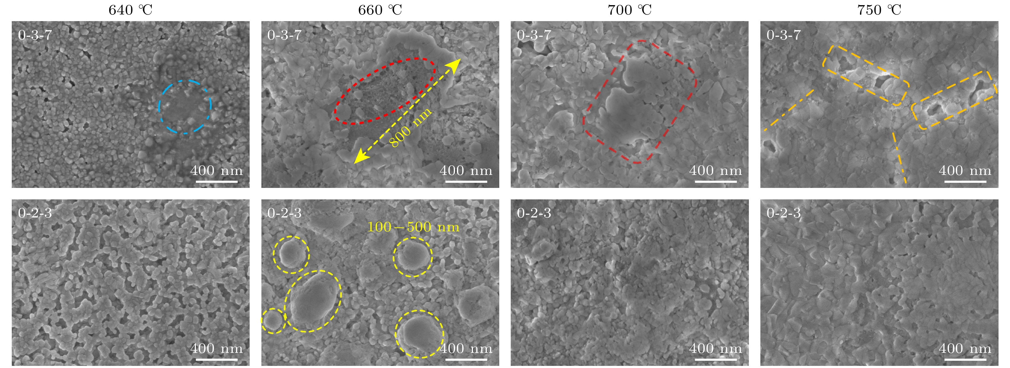
图 4 $ {P_{{{\text{O}}_{2}}}} $ = 100 Pa, Y∶Ba∶Cu = 0∶3∶7和Y∶Ba∶Cu = 0∶2∶3两组分的液相在中高温热处理过程中的演变, 其中蓝虚线圈为液相痕迹, 红椭圆-蜂窝状为熔融凝固态, 红圆角矩形为大液相区, 橙圆角矩形为液相之间的空隙, 橙虚线标识液相间的分界线, 黄虚线圈为点状液相区
Figure 4. $ {P_{{{\text{O}}_{2}}}} $ = 100 Pa, the evolution of the liquid phase of Y∶Ba∶Cu = 0∶3∶7 and Y∶Ba∶Cu = 0∶2∶3 during medium and high temperature heat treatment, where blue dotted circle represents liquid phase trace; red ellipse represents honeycomb molten solid state; red rounded rectangle represents large liquid phase area; orange rounded rectangle represents gap between liquid phases, orange dotted line marks the boundary between liquid phases; yellow dotted circle represents pointed liquid phase area.
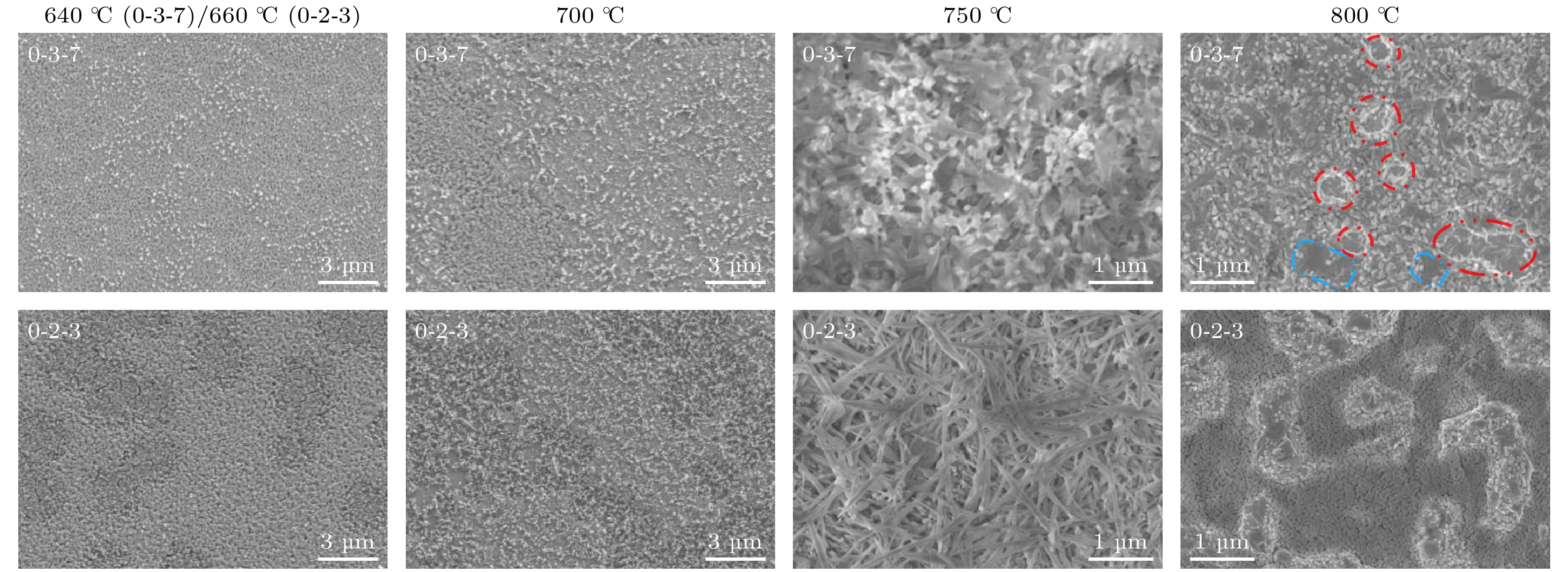
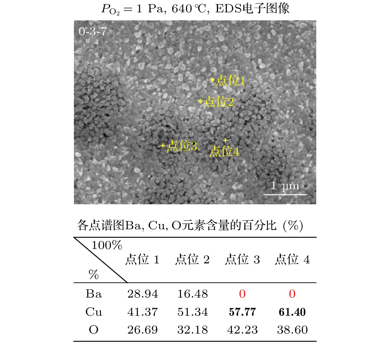
图 5 $ {P_{{{\text{O}}_{2}}}} $ = 1 Pa, Y∶Ba∶Cu = 0∶3∶7和Y∶Ba∶Cu = 0∶2∶3两组分的液相在中高温热处理过程中的演变, 其中红虚线圈为液相间的空隙, 蓝虚线框为液相层的阶梯状分布
Figure 5. Evolution of the liquid phase of two components of $ {P_{{{\text{O}}_{2}}}} $ = 1 Pa, Y∶Ba∶Cu = 0∶3∶7 and Y∶Ba∶Cu = 0∶2∶3 during medium and high temperature heat treatment, where red dotted circle-the gap between the liquid phases, blue dotted frame-the stepped distribution of the liquid phase layer.
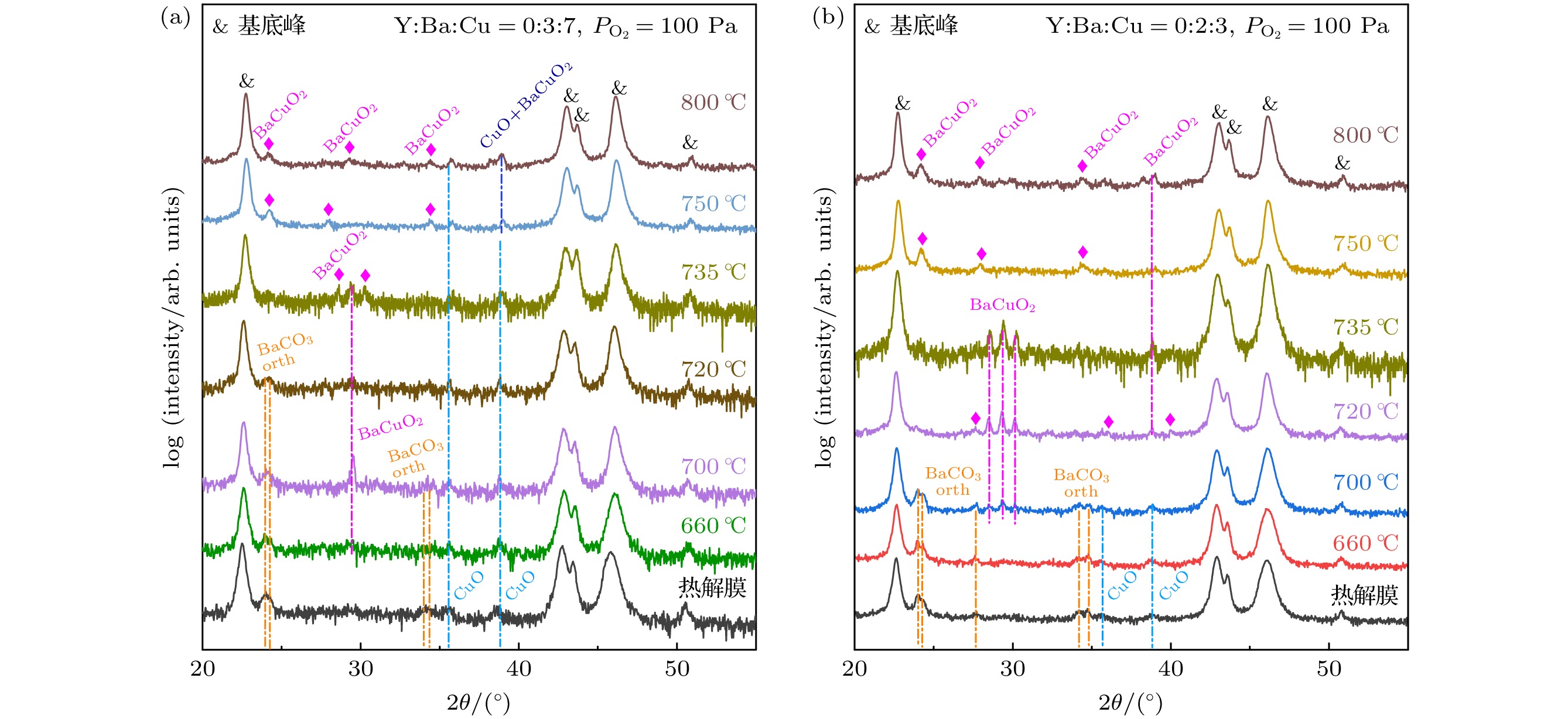
图 8 $ {P_{{{\text{O}}_{2}}}} $ = 100 Pa, Y∶Ba∶Cu = 0∶3∶7和Y∶Ba∶Cu = 0∶2∶3两组分薄膜中高温热处理过程的物相演变, 不同温度是指淬火温度, 由于该实验氧分压属于高氧分压[28] (CuO不会被还原), 因此淬火在室温中进行
Figure 8. Phase evolution during high temperature heat treatment of two-component films with $ {P_{{{\text{O}}_{2}}}} $= 100 Pa, Y∶Ba∶Cu = 0∶3∶7 and Y∶Ba∶Cu = 0∶2∶3, the different temperatures refer to the quenching temperatures, the quenching was performed at room temperature because the oxygen partial pressure in this experiment was high[28] (CuO would not be reduced).
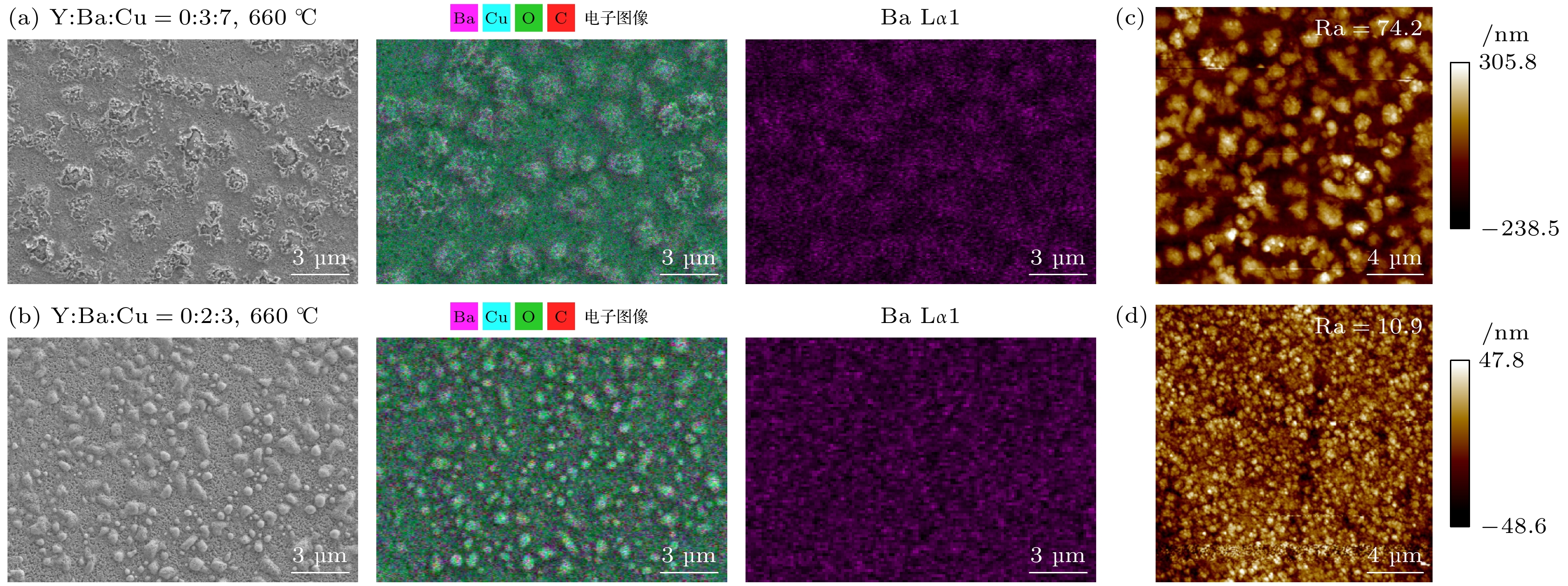
图 9 (a), (b) $ {P_{{{\text{O}}_{2}}}} $ = 100 Pa, 660 ℃下Y∶Ba∶Cu = 0∶3∶7和Y∶Ba∶Cu = 0∶2∶3两组分薄膜表面SEM图以及对应的EDS元素扫描和Ba元素的表面分布图; (c), (d) Y∶Ba∶Cu = 0∶3∶7和Y∶Ba∶Cu = 0∶2∶3两组分薄膜的AFM扫描图像
Figure 9. (a), (b) $ {P_{{{\text{O}}_{2}}}} $ = 100 Pa: SEM images of the surface of the two-component films Y∶Ba∶Cu = 0∶3∶7 and Y∶Ba∶Cu = 0∶2∶3 at 660 ℃, and the corresponding EDS element scans and surface distribution of Ba elements; (c), (d) AFM scan images of the corresponding two-component films.
图 10 $ {P_{{{\text{O}}_{2}}}} $ = 1 Pa, Y∶Ba∶Cu = 0∶3∶7和Y∶Ba∶Cu = 0∶2∶3两组分薄膜中高温热处理过程的物相演变, 不同温度是指淬火温度, 由于该实验氧分压属于低氧分压[28] (CuO会被还原), 因此淬火是在液氮中进行
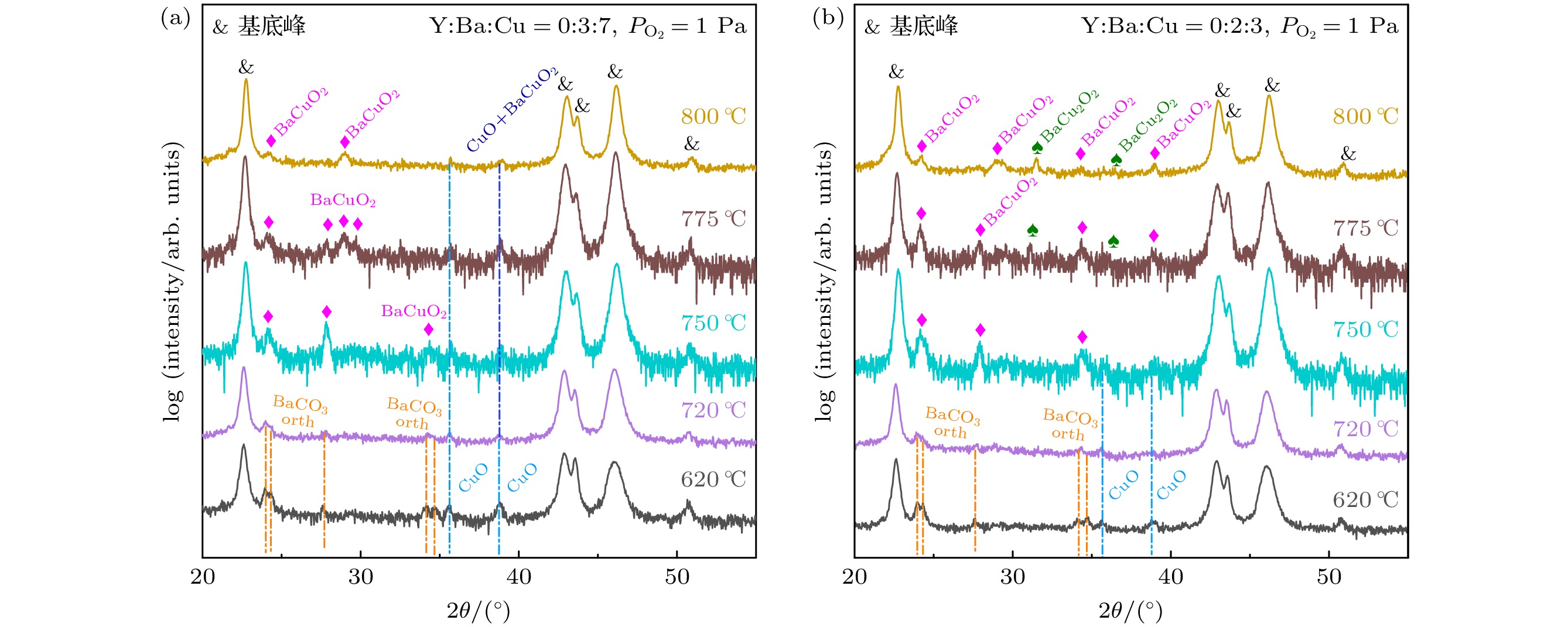
Figure 10. Phase evolution during high temperature heat treatment of two-component films with $ {P_{{{\text{O}}_{2}}}} $ = 1 Pa, Y∶Ba∶Cu = 0∶3∶7 and Y∶Ba∶Cu = 0∶2∶3, the different temperatures refer to the quenching temperatures, the quenching was performed in liquid nitrogen because the oxygen partial pressure in this experiment was low[28] (CuO would be reduced).
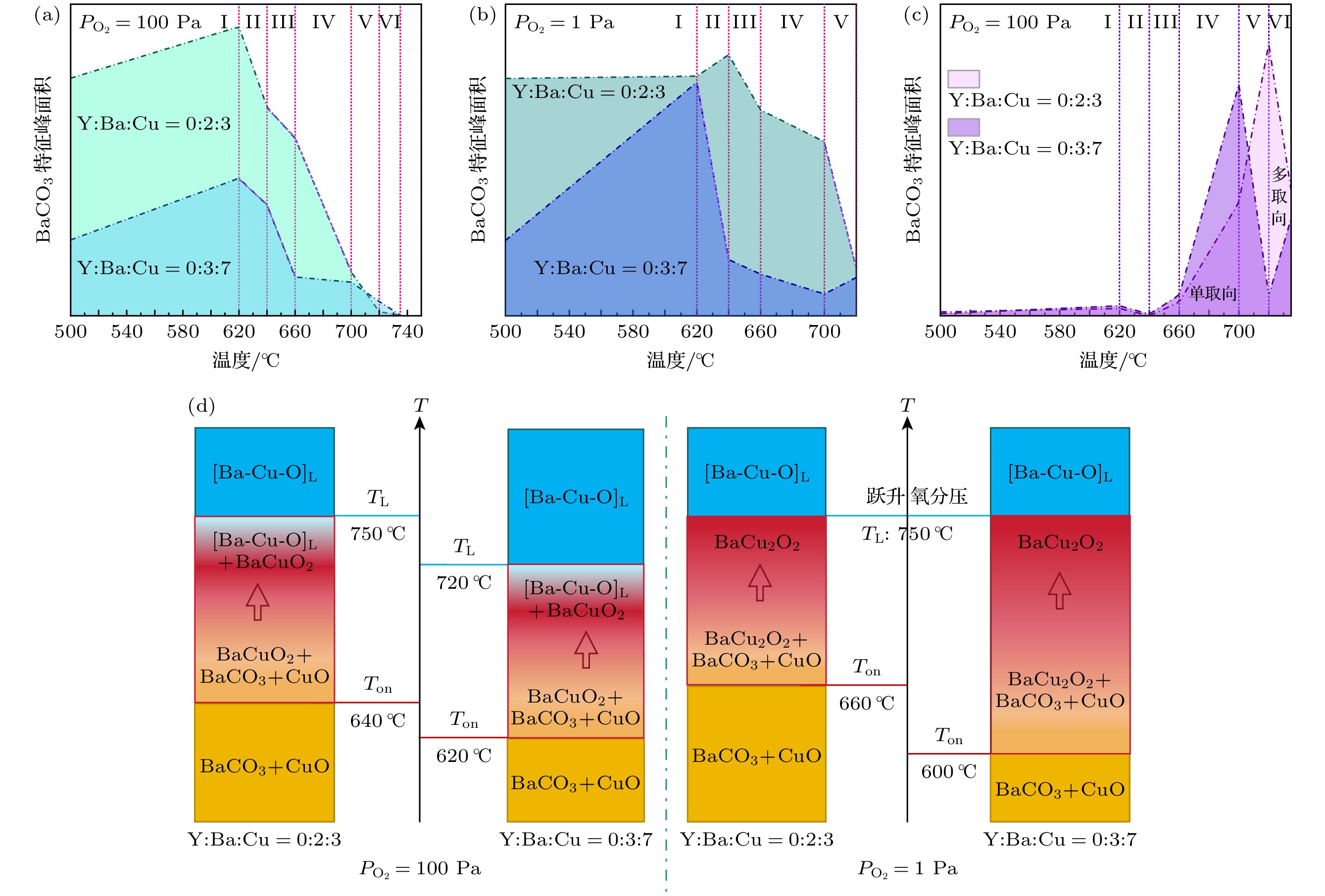
图 11 (a)—(c)不同氧分压下, Y∶Ba∶Cu = 0∶3∶7和Y∶Ba∶Cu = 0∶2∶3两组分的BaCO3和BaCuO2特征峰面积随温度的变化, 紫虚线表示两曲线的下降斜率一致, 罗马数字表示不同的温区; (d) Ton是BaCO3的分解温度, TL是形成完全液相的温度
Figure 11. (a)–(c) Characteristic peak areas of BaCO3 and BaCuO2 of Y∶Ba∶Cu = 0∶3∶7 and Y∶Ba∶Cu = 0∶2∶3 under different oxygen partial pressures vary with temperature, the purple dashed line indicates that the two curves have the same downward slope, and the Roman numerals represent different temperature zones; (d) Ton is the decomposition temperature of BaCO3, and TL is the temperature at which a complete liquid phase is formed.
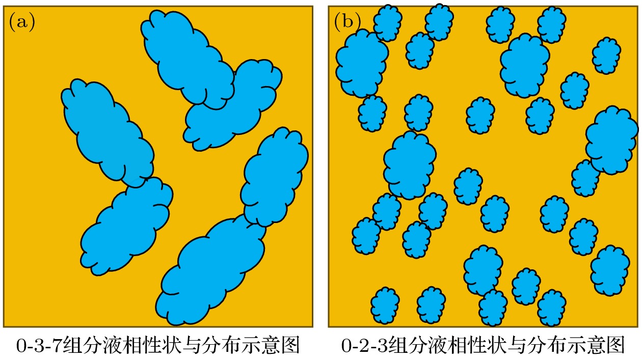
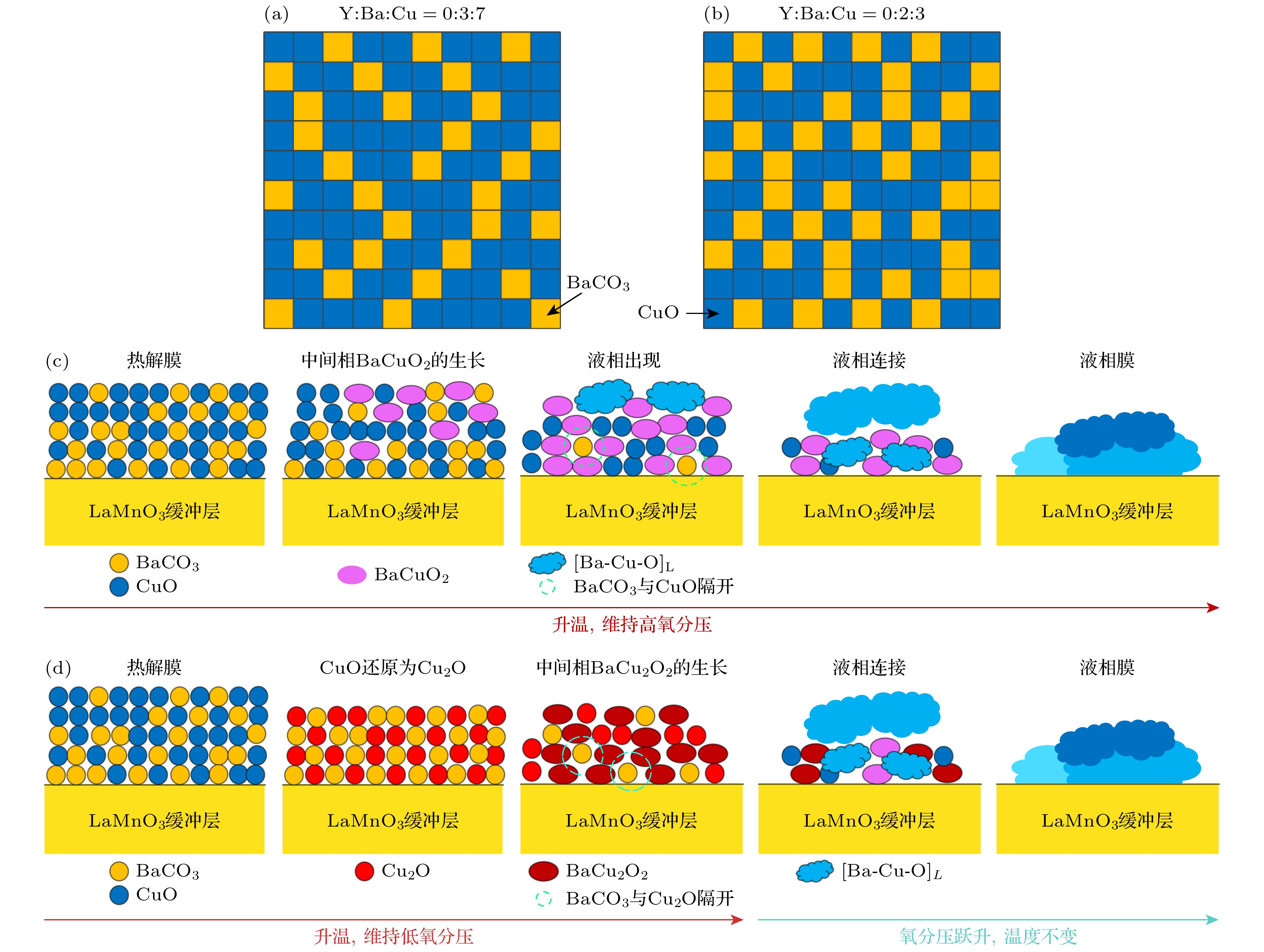
图 12 (a), (b) Y∶Ba∶Cu = 0∶3∶7和Y∶Ba∶Cu = 0∶2∶3组分的前驱相颗粒均匀分布示意图; (c), (d) 高、低氧分压下完全[Ba-Cu-O]L膜的形成示意图
Figure 12. (a), (b) Schematic diagrams of uniform distribution of precursor phase particles of Y∶Ba∶Cu = 0∶3∶7 and Y∶Ba∶Cu = 0∶2∶3 components, respectively; (c), (d) schematic diagrams of the formation of complete [Ba-Cu-O]L film under high and low oxygen partial pressures, respectively.
-
[1] Zhou Y H, Park D, Iwasa Y 2023 Natl. Sci. Rev. 10 nwad001
 Google Scholar
[2] Obradors X, Puig T 2014 Supercond. Sci. Technol. 27 044003
 Google Scholar
[3] Barth C, Komorowski P, Vonlanthen P, Herzog R, Tediosi R, Alessandrini M, Bonura M, Senatore C 2019 Supercond. Sci. Technol. 32 075005
 Google Scholar
[4] Chow C C T, Ainslie M D, Chau K T 2023 Energy Rep. 9 1124
 Google Scholar
[5] Favre S, Ariosa D, Yelpo C, Mazini M, Faccio R 2021 Mater. Chem. Phys. 266 124507
 Google Scholar
[6] Khan M Z, Rivasto E, Tikkanen J, Rijckaert H, Malmivirta M, Liedke M O, Butterling M, Wagner A, Huhtinen H, Van Driessche I, Paturi P 2019 Sci. Rep. 9 15425
 Google Scholar
[7] Yang T W, Wang L M 2023 IEEE Trans. Appl. Supercond. 33 1
 Google Scholar
[8] Chen X, Tao B, Zhao R, Yang K, Li Z, Xie T, Zhong Y, Zhang T, Xia Y 2023 Mater. Lett. 330 133336
 Google Scholar
[9] Chen T Y, Xia Y D, Zhao R P, Wu D, Feng Z P, Yang J T, Xin J J, Wang W, Jin K, Tao B W 2022 Ceram. Int. 48 17837
 Google Scholar
[10] Zhao P, Wang Y, Huang Z L, Mao Y, Xu Y L 2015 J. Cryst. Growth 415 152
 Google Scholar
[11] Jin L H, Bai Y, Li C S, Feng J Q, Lei L, Zhao G Y, Gao L, Zhang P X 2019 Mater. Lett. 250 34
 Google Scholar
[12] Wesolowski D E, Patta Y R, Cima M J 2009 Phys. C Supercond. 469 766
 Google Scholar
[13] Bhuiyan M S, Paranthaman M, Salama K 2006 Supercond. Sci. Technol. 19 R1
 Google Scholar
[14] Chu J Y, Zhao Y, Khan M Z, Tang X, Wu W, Shi J T, Wu Y, Huhtinen H, Suo H L, Jin Z J 2019 Cryst. Growth Des. 19 6752
 Google Scholar
[15] Soler L, Jareño J, Banchewski J, Rasi S, Chamorro N, Guzman R, Yáñez R, Mocuta C, Ricart S, Farjas J, Roura-Grabulosa P, Obradors X, Puig T 2020 Nat. Commun. 11 344
 Google Scholar
[16] Shi J T, Zhao Y, Jiang G Y, Zhu J M, Wu Y, Gao Y S, Quan X L, Yu X, Wu W, Jin Z J 2021 J. Eur. Ceram. Soc. 41 5223
 Google Scholar
[17] Chu J Y, Zhao Y, Ji Y T, Wu W, Shi J T, Hong Z Y, Ma L, Suo H L, Jin Z J 2019 J. Am. Ceram. Soc. 102 5705
 Google Scholar
[18] Chu N, Liu Z Y, Yang Z, Tong S, Shen J, Chen J, Cai C B 2022 Jpn. J. Appl. Phys. 61 075509
 Google Scholar
[19] Shen J J, Liu Z Y, Chen J, Zhou X H, Li Y G, Cai C B 2022 J. Supercond. Nov. Magn. 35 3147
 Google Scholar
[20] Saltarelli L, Gupta K, Rasi S, Kethamkuzhi A, Queraltó A, Garcia D, Gutierrez J, Farjas J, Roura-Grabulosa P, Ricart S, Obradors X, Puig T 2022 ACS Appl. Mater. Interfaces 14 48582
 Google Scholar
[21] Rasi S, Queraltó A, Banchewski J, Saltarelli L, Garcia D, Pacheco A, Gupta K, Kethamkuzhi A, Soler L, Jareño J, Ricart S, Farjas J, Roura-Grabulosa P, Mocuta C, Obradors X, Puig T 2022 Adv. Sci. 9 2203834
 Google Scholar
[22] Vermeir P, Cardinael I, Schaubroeck J, Verbeken K, Bäcker M, Lommens P, Knaepen W, D’haen J, De Buysser K, Van Driessche I 2010 Inorg. Chem. 49 4471
 Google Scholar
[23] Rasi S, Soler L, Jareño J, Banchewski J, Guzman R, Mocuta C, Kreuzer M, Ricart S, Roura-Grabulosa P, Farjas J, Obradors X, Puig T 2020 J. Phys. Chem. C 124 15574
 Google Scholar
[24] Zhou X H, Chen J, Huang R T, Liu Z Y, Cai C B 2024 Colloids Surf. Physicochem. Eng. Asp. 691 133830
 Google Scholar
[25] Lee J H, Lee H, Lee J W, Choi S M, Yoo S I, Moon S H 2014 Supercond. Sci. Technol. 27 044018
 Google Scholar
[26] Song X, Daniels G, Feldmann D M, Gurevich A, Larbalestier D 2005 Nat. Mater. 4 470
 Google Scholar
[27] Heinig N F, Redwing R D, Tsu I F, Gurevich A, Nordman J E, Babcock S E, Larbalestier D C 1996 Appl. Phys. Lett. 69 577
 Google Scholar
[28] Soler L B 2019 Ph. D. Dissertation (Barcelona: Universitat Autònoma de Barcelona
[29] Shiohara Y, Goodilin E A 2000 Handbook on the Physics and Chemistry of Rare Earths 2000 pp67–227
[30] Zhou X H, Chen J, Huang R T, Tao J Q, Fu Y X, Li M J, Liu Z Y, Cai C B 2024 Colloids Surf. Physicochem. Eng. Asp. 702 135106
 Google Scholar
[31] Chu P Y, Buchanan R C 1993 J. Mater. Res. 8 2134
 Google Scholar
[32] Nevřiva M, Pollert E, Matějková L, Tříska A 1988 J. Cryst. Growth 91 434
 Google Scholar
[33] Zhang W, Osamura K, Ochiai S 1990 J. Am. Ceram. Soc. 73 1958
 Google Scholar
Catalog
Metrics
- Abstract views: 2566
- PDF Downloads: 90
- Cited By: 0


 DownLoad:
