


-
In order to solve the problem that the measurement arm length needs to be obtained in real time when calculating the measurement angle in the process of Tolansky interference small angle measurement, a dual-arm Tolansky interference autocollimation angle measurement scheme is proposed, which not only maintains the function of Tolansky interference, but also integrates the principle of optical leverage. In the simulation study, it is found that the splitter with thickness in the scheme will lead to the lateral offset of the optical axis of the emitted light, which will change the position of the virtual point light source, and finally change the position of the center of the interference circle on the detector. In this work, in order to reduce the influence of the thickness of the beam splitter on the angle measurement accuracy of the angle measurement scheme, the optical path structure of the angle measurement scheme is redrawn, and the relationship between the center offset of the interference ring and the deflection angle, which contains the thickness factor and can accurately describe the optical path, is deduced. Therefore, the corresponding method is adopted as follows. Firstly, the measurement optical path of the splitter with a thickness factor is redrawn, the splitter is partially enlarged, and the original beam is replaced with the center line of the laser beam to draw the optical path. Then, the position of the virtual point light source under the influence of the thickness of the splitter is analyzed by using the single refraction spherical formula and the transition formula of geometric optics, and the relationship between the offset of the interference center and the deflection angle with the thickness of the splitter is established. Secondly, the coordinate information of the center of the interference ring under different thickness parameters of the splitter is obtained by using the virtual simulation experiment, which proves the correctness of the theoretical analysis. Then, simulation experiments such as simulation measurement of multiple sets of setting angles and angle measurement under different splitter thickness conditions are carried out, and the accuracy of the relationship including the splitter thickness factor deduced above is cross-validated. Finally, combined with the actual experiment, measurements are taken on the guide rail and calibrated autocollimator, and the influence of beam splitter thickness on angle measurement accuracy is investigated in detail. The research results are obtained below. Experiments show that the thickness of the splitter will affect the position of the initial center of the circle; with the increase of the thickness of the splitter, the error between the simulation measurement results and the relationship including the thickness factor is within ± 0.5 % at different angles, and the experimental data and theoretical results are in good agreement. At the same angle, as the thickness of the beam splitter increases, the difference between the established relationship and the approximate relationship gradually increases. With 1-mm-thick beam splitter, the relative error between the established relationship and the calculated value of the approximate relationship is only 0.22 % based on the data of the guide rail measured by the calibrated autocollimator. From these results, a conclusion can be drawn below. The utilizing a thinner spectroscope can effectively reduce the calculation and measurement errors, providing an important guidance for carrying out the in-depth research and development of this new autocollimator.
-
Keywords:
- Tolansky interference /
- autocollimator /
- concentric rings /
- micro/small angle
[1] She C, Xu L, Shan X D, Zhu H, Zhou Y, Wang Q L 2021 Appl. Opt. 60 8016
 Google Scholar
[2] Shimizu Y, Matsukuma H, Wei G 2019 Sensors 19 5289
Google Scholar
[3] Zhao Y K, Fan X W, Wang C C, Lu L 2020 Opt. Lasers Eng. 126 105866
Google Scholar
[4] Geckeler R D, Krause M, Just A, Kranz O, Bosse H 2015 Measurement 73 231
Google Scholar
[5] Zhang M S 2021 J. Phys. Conf. Ser. 1952 022020
Google Scholar
[6] 付鹏, 张艳春, 赵涛, 赵勇明, 唐松, 李颖, 韩沈丹 2023 中国激光 51 219
Google Scholar
Fu P, Zhang Y C, Zhao T, Zhao Y M, Tang S, Li Y, Han S D 2023 Chin. J. Lasers 51 219
Google Scholar
[7] Wang S X, Kong L B, Wang C J, Cheung C F 2023 Opt. Express 31 2234
Google Scholar
[8] Wu C G, Shen X Y 2023 Journal of China Jiliang University 34 342(in Chinese)[吴晨光, 沈小燕 2023 中国计量大学学报 34 342]
[9] 吴晨光, 沈小燕, 周世男 2023中国测试 (网络首发)
Wu C G, Shen X Y, Zhou S N 2023 China Measurem. Test (In press
[10] 陈秋霞 2006 红外 8 33
Google Scholar
Chen Q X 2006 Infrared 8 33
Google Scholar
[11] 陈颖, 张学典, 逯兴莲, 张振一, 潘丽娜 2011 光机电信息 28 6
Google Scholar
Chen Y, Zhang X D, Lu X L, Zhang Z Y, Pan L N 2011 OME Inf. 28 6
Google Scholar
[12] Xu W, Xu W H, Bouet N, Zhou J, Yan H F, Huang X J, Huang L, Lu M, Maxim Z, Chu Y S, Nazaretski E 2023 Opt. Lasers Eng. 161 107331
Google Scholar
[13] 蓝旭辉 2020 硕士学位论文 (杭州: 中国计量大学)
Lan X H 2020 M. S. Thesis (Hangzhou: China Jiliang University
[14] Guo C Y, Zhou Z J, Wu R, Su Z Y 2024 Opt. Fiber Technol. 86 103841
Google Scholar
[15] Larichev R A, Filatov Y V 2013 J. Opt. Technol. 80 554
Google Scholar
[16] Korolev A N, Gartsuev A I, Polishchuk G S, Tregub V P 2009 J. Opt. Technol. 76 624
Google Scholar
[17] Shen M Z, Liao S T 2005 KEM 295-296 337
Google Scholar
[18] 张宝武, 崔建军, 欧阳烨锋, 陈恺, 方振远 2023 计量学报 44 1202
Google Scholar
Zhang B W, Cui J J, Ouyang Y F, Chen K, Fang Z Y 2023 Acta Metrolog. Sin. 44 1202
Google Scholar
[19] 欧阳烨锋, 许子杰, 张宝武, 朱玲, 方振远, 罗贤欢, 孙怡 2024 光学学报 44 0526001
Google Scholar
Ouyang Y F, Xu Z J, Zhang B W, Zhu L, Fang Z Y, Luo X H, Sun Y 2024 Acta Opt. Sin. 44 0526001
Google Scholar
[20] 许子杰, 张宝武, 施江焕, 欧阳烨锋, 朱玲, 方振远 2024 光学技术 50 459
Google Scholar
Xu Z J, Zhang B W, Shi J H, Ouyang Y F, Zhu L, Fang Z Y 2024 Opt. Techn. 50 459
Google Scholar
[21] 张宝武, 许子杰, 施江焕, 朱玲, 方振远, 孙怡, 罗贤欢 2024 中国计量大学学报 35 1
Google Scholar
Zhang B W, Xu Z J, Shi J H, Zhu L, Fang Z Y, Sun Y, Luo X H 2024 J. China Jiliang Univ. 35 1
Google Scholar
[22] 欧阳烨锋, 张宝武, 李玉彬, 朱玲, 方振远, 薛财文 2023 中国计量大学学报 34 541
Google Scholar
Ouyang Y F, Li Y B, Zhu L, Fang Z Y, Xue C W 2023 J. China Jiliang Univ. 34 541
Google Scholar
[23] 欧阳烨锋, 崔建军, 张宝武, 陈恺, 杨宁, 方振远 2024 激光技术 48 135
Google Scholar
Ouyang Y F, Cui J J, Zhang B W, Chen K, Yang N, Fang Z Y 2024 Laser Techn. 48 135
Google Scholar
-
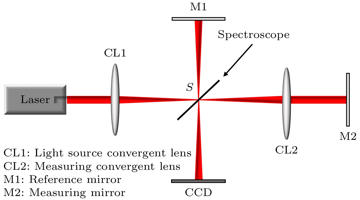
图 1 Tolansky干涉自准直仪模型
Figure 1. Tolansky interference autocollimator model.
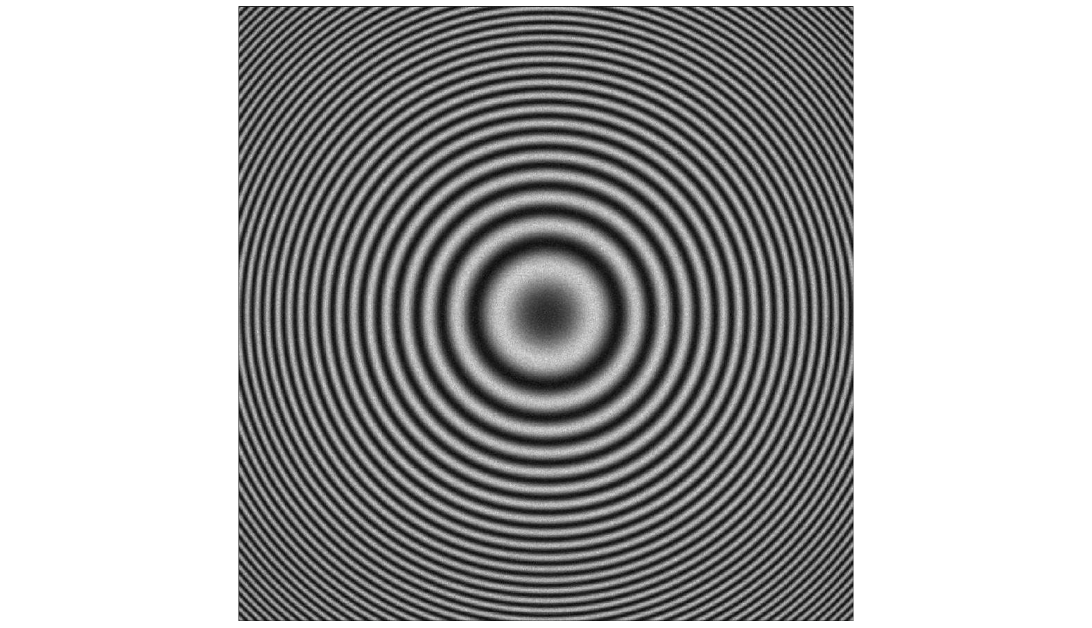
图 2 同心圆环干涉图像
Figure 2. Concentric ring interference image.
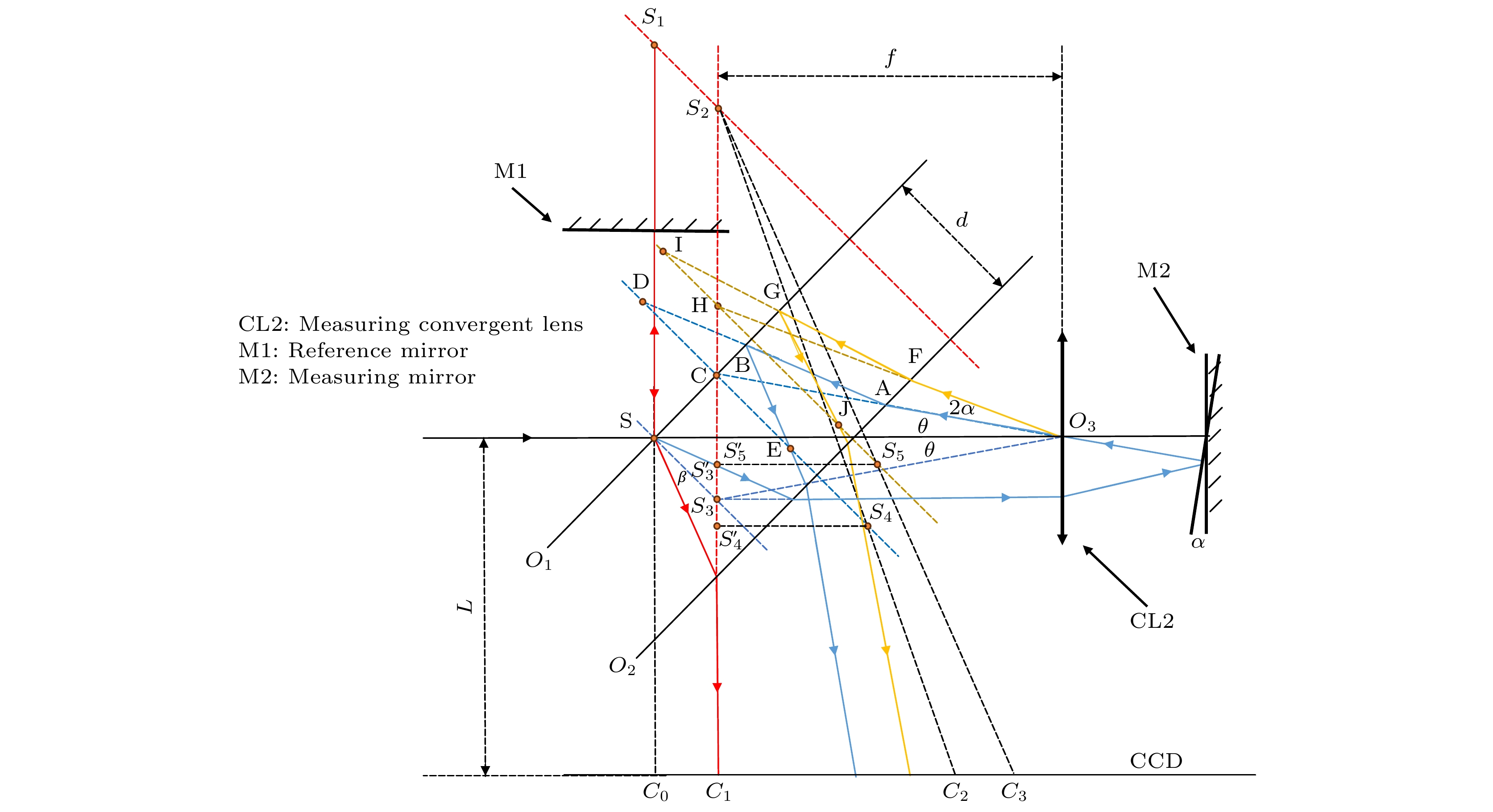
图 3 干涉自准直仪原理图
Figure 3. Schematic diagram of interference autocollimator.
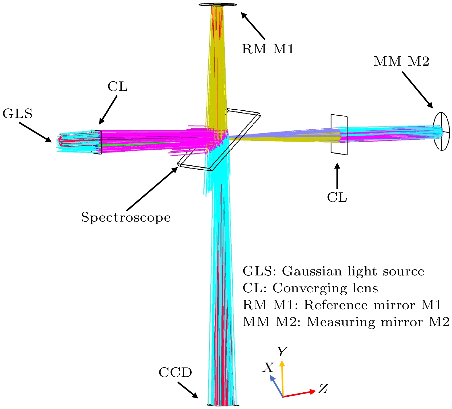
图 4 Tolansky干涉自准直仪仿真模型
Figure 4. Simulation model of Tolansky interferometric autocollimator.
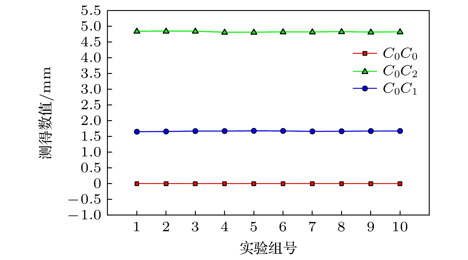
图 5 实验一仿真数据与理论数据
Figure 5. The simulation data and theoretical data of Experiment 1.
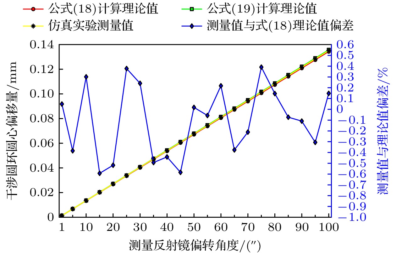
图 6 X轴偏转仿真数据与理论数据误差
Figure 6. Simulation data of X-axis deflection and theoretical data error.
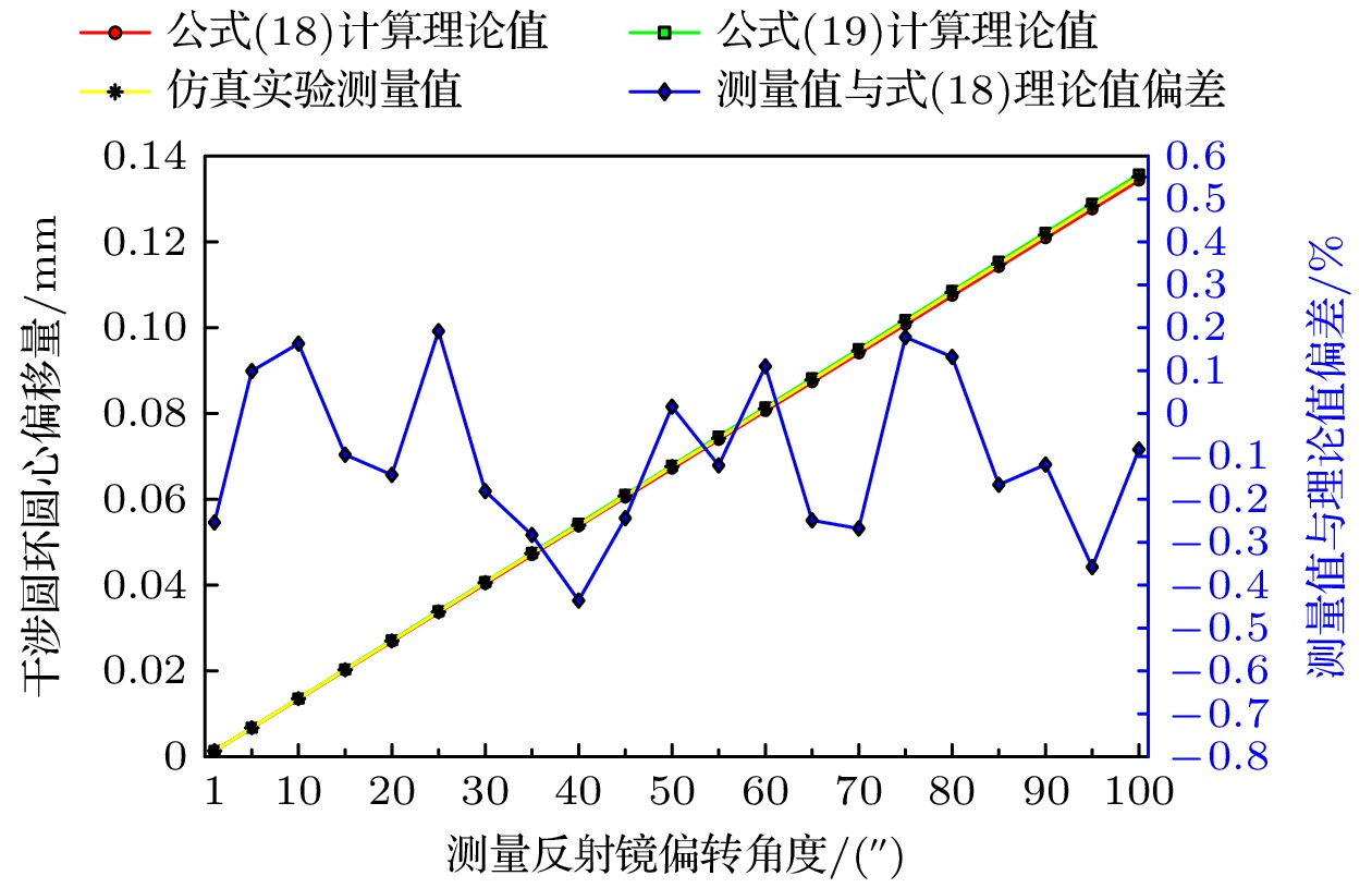
图 7 Y轴偏转仿真数据与理论数据误差
Figure 7. Simulation data of Y-axis deflection and theoretical data error.
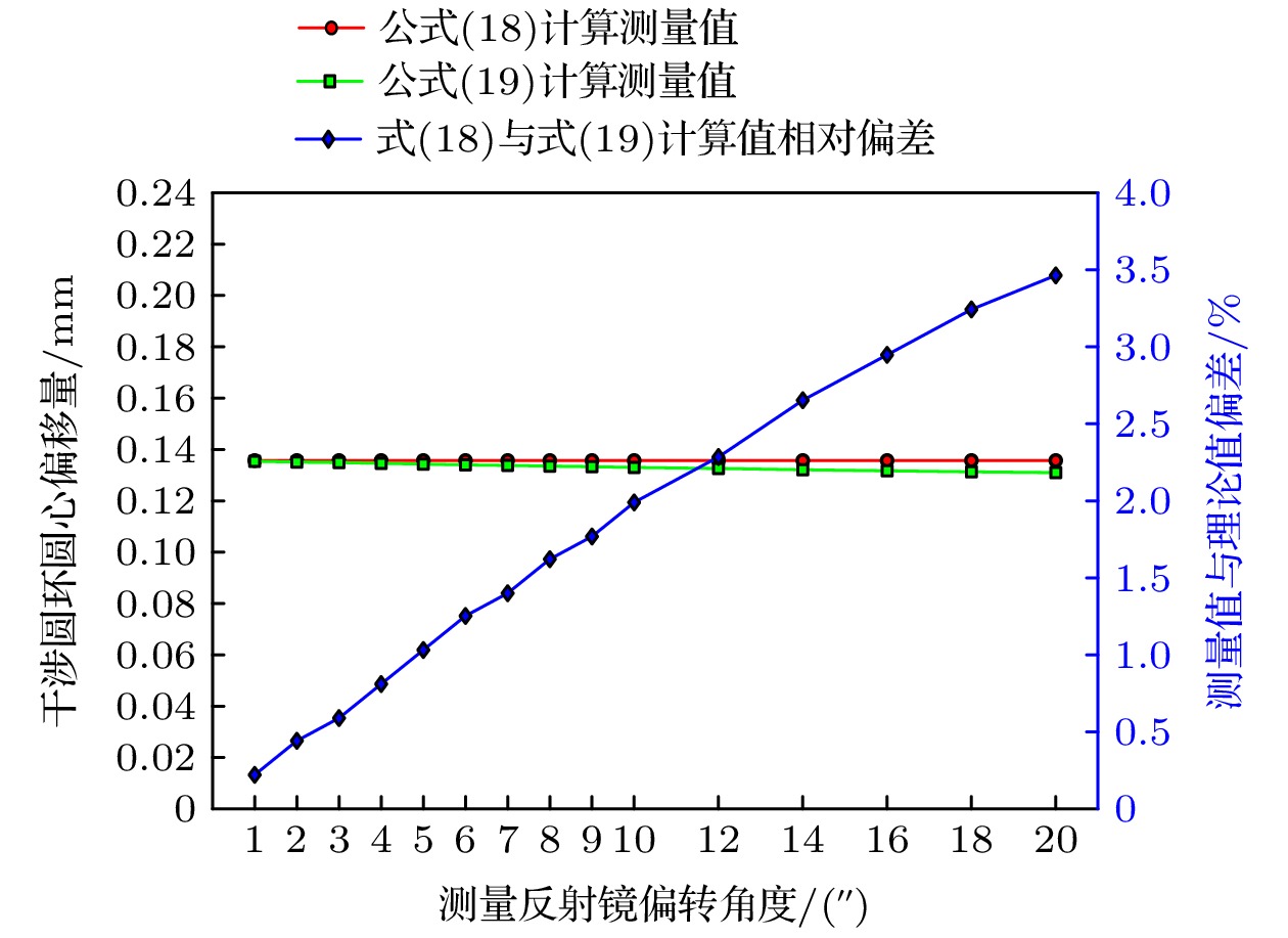
图 8 圆心偏移量随分光镜厚度变化趋势图
Figure 8. The change trend of center offset with the thickness of the beam splitter.
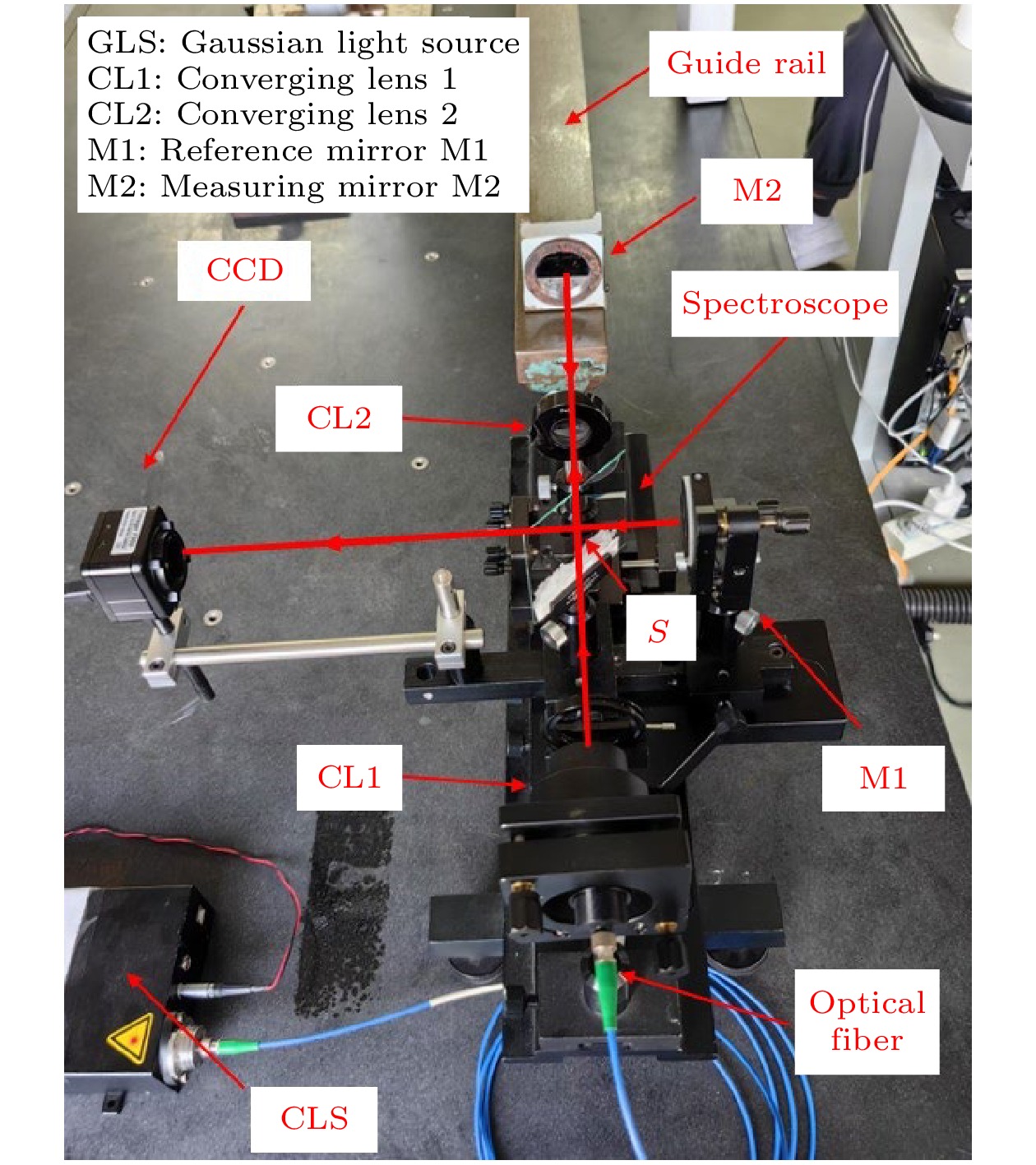
图 9 双臂Tolensky干涉实体仪器
Figure 9. Dual-arm Tolensky interference entity instrument.

表 1 Zemax软件参数设置
Table 1. Zemax software parameter settings.
物体类型 参数 激光源 高斯激光, 波长 632 nm, 光源宽度 5 mm. 会聚透镜 镜片直径 12 mm, 厚度 1 mm 分光镜 尺寸 20 mm × 20 mm, 厚度可调节, x 轴倾斜 45° 参考反射镜 直径 10 mm, 厚度不计, x 轴倾斜 –90° 测量反射镜 直径 10 mm, 厚度不计, 无倾斜 CCD 接收面尺寸 12.8 mm × 12.8 mm, x 轴倾斜 90° 参考臂臂长$ {D}_{1} $ 初始长度 70 mm, 臂长可调节 测量臂臂长$ {D}_{2} $ 初始长度 130 mm, 臂长可调节 相机距离L 初始长度 140 mm, 距离可调节 空气折射率 $ {n}_{0}=1.00029 $ 玻璃折射率 $ n=1.5168 $  DownLoad: CSV
表 2 实验一参数
Table 2. Parameters of Experiment 1.
实验对象 分光镜
厚度/mm会聚透镜
CL2位置理论
数值/mm$ {C}_{0}{C}_{0} $ 0 固定 0 $ {C}_{0}{C}_{2} $ 5 固定 4.822735 $ {C}_{0}{C}_{1} $ 5 下移 1.671882
DownLoad: CSV
表 3 实验二参数设置
Table 3. Parameter setting of Experiment 2.
物体类型 参数 分光镜 尺寸 20 mm × 20 mm, 厚度 5 mm CCD 相机距离 $ L=140 $mm 参考臂臂长 $ {D}_{1}=70 $mm 会聚透镜焦距 $ f=70 $mm
DownLoad: CSV
-
[1] She C, Xu L, Shan X D, Zhu H, Zhou Y, Wang Q L 2021 Appl. Opt. 60 8016
Google Scholar
[2] Shimizu Y, Matsukuma H, Wei G 2019 Sensors 19 5289
Google Scholar
[3] Zhao Y K, Fan X W, Wang C C, Lu L 2020 Opt. Lasers Eng. 126 105866
Google Scholar
[4] Geckeler R D, Krause M, Just A, Kranz O, Bosse H 2015 Measurement 73 231
Google Scholar
[5] Zhang M S 2021 J. Phys. Conf. Ser. 1952 022020
Google Scholar
[6] 付鹏, 张艳春, 赵涛, 赵勇明, 唐松, 李颖, 韩沈丹 2023 中国激光 51 219
Google Scholar
Fu P, Zhang Y C, Zhao T, Zhao Y M, Tang S, Li Y, Han S D 2023 Chin. J. Lasers 51 219
Google Scholar
[7] Wang S X, Kong L B, Wang C J, Cheung C F 2023 Opt. Express 31 2234
Google Scholar
[8] Wu C G, Shen X Y 2023 Journal of China Jiliang University 34 342(in Chinese)[吴晨光, 沈小燕 2023 中国计量大学学报 34 342]
[9] 吴晨光, 沈小燕, 周世男 2023中国测试 (网络首发)
Wu C G, Shen X Y, Zhou S N 2023 China Measurem. Test (In press
[10] 陈秋霞 2006 红外 8 33
Google Scholar
Chen Q X 2006 Infrared 8 33
Google Scholar
[11] 陈颖, 张学典, 逯兴莲, 张振一, 潘丽娜 2011 光机电信息 28 6
Google Scholar
Chen Y, Zhang X D, Lu X L, Zhang Z Y, Pan L N 2011 OME Inf. 28 6
Google Scholar
[12] Xu W, Xu W H, Bouet N, Zhou J, Yan H F, Huang X J, Huang L, Lu M, Maxim Z, Chu Y S, Nazaretski E 2023 Opt. Lasers Eng. 161 107331
Google Scholar
[13] 蓝旭辉 2020 硕士学位论文 (杭州: 中国计量大学)
Lan X H 2020 M. S. Thesis (Hangzhou: China Jiliang University
[14] Guo C Y, Zhou Z J, Wu R, Su Z Y 2024 Opt. Fiber Technol. 86 103841
Google Scholar
[15] Larichev R A, Filatov Y V 2013 J. Opt. Technol. 80 554
Google Scholar
[16] Korolev A N, Gartsuev A I, Polishchuk G S, Tregub V P 2009 J. Opt. Technol. 76 624
Google Scholar
[17] Shen M Z, Liao S T 2005 KEM 295-296 337
Google Scholar
[18] 张宝武, 崔建军, 欧阳烨锋, 陈恺, 方振远 2023 计量学报 44 1202
Google Scholar
Zhang B W, Cui J J, Ouyang Y F, Chen K, Fang Z Y 2023 Acta Metrolog. Sin. 44 1202
Google Scholar
[19] 欧阳烨锋, 许子杰, 张宝武, 朱玲, 方振远, 罗贤欢, 孙怡 2024 光学学报 44 0526001
Google Scholar
Ouyang Y F, Xu Z J, Zhang B W, Zhu L, Fang Z Y, Luo X H, Sun Y 2024 Acta Opt. Sin. 44 0526001
Google Scholar
[20] 许子杰, 张宝武, 施江焕, 欧阳烨锋, 朱玲, 方振远 2024 光学技术 50 459
Google Scholar
Xu Z J, Zhang B W, Shi J H, Ouyang Y F, Zhu L, Fang Z Y 2024 Opt. Techn. 50 459
Google Scholar
[21] 张宝武, 许子杰, 施江焕, 朱玲, 方振远, 孙怡, 罗贤欢 2024 中国计量大学学报 35 1
Google Scholar
Zhang B W, Xu Z J, Shi J H, Zhu L, Fang Z Y, Sun Y, Luo X H 2024 J. China Jiliang Univ. 35 1
Google Scholar
[22] 欧阳烨锋, 张宝武, 李玉彬, 朱玲, 方振远, 薛财文 2023 中国计量大学学报 34 541
Google Scholar
Ouyang Y F, Li Y B, Zhu L, Fang Z Y, Xue C W 2023 J. China Jiliang Univ. 34 541
Google Scholar
[23] 欧阳烨锋, 崔建军, 张宝武, 陈恺, 杨宁, 方振远 2024 激光技术 48 135
Google Scholar
Ouyang Y F, Cui J J, Zhang B W, Chen K, Yang N, Fang Z Y 2024 Laser Techn. 48 135
Google Scholar


 DownLoad:


Catalog
Metrics
- Abstract views: 2630
- PDF Downloads: 51
- Cited By: 0
