


-
偏滤器脱靶是中国环流三号装置(HL-3)偏滤器热负载的主要控制手段. 然而目前的脱靶工作缺少对刮削层-偏滤器区域内复杂多成分粒子问题的研究, 如氢同位素(如氘)、外部注入杂质(如氖杂质)、内部固有杂质(如碳杂质)的碰撞、辐射等过程. 本工作使用新开发的刮削层-偏滤器多成分粒子输运程序SD1D, 研究了碳杂质和中性粒子对中国环流三号上抬升等离子体密度和偏滤器氖气注入两种脱靶方式的影响. 研究发现, 偏滤器产生的碳杂质对于抬升密度的脱靶方式具有促进作用, 但是对注入氖气实现脱靶的过程影响较小. 此外, 本工作还发现中性粒子(氘原子与氘分子)在这两种脱靶过程中的重要性也有很大的差别: 抬升等离子体密度可以促进偏滤器内再循环过程产生大量中性粒子, 等离子体与中性粒子反应导致的能量与动量损失是实现脱靶的关键因素; 向偏滤器内注入氖气直接降低了靶板上饱和电流, 抑制了再循环过程, 中性粒子的重要性也随之降低.
Divertor detachment is a critical technique for managing the thermal load on the divertor of the HL-3 tokamak, an important device in magnetic confinement fusion research. However, existing studies on detachment have largely overlooked the complex multi-species particle dynamics in the scrape-off layer (SOL) and divertor regions, particularly the interactions involving hydrogen isotopes (e.g, deuterium), externally injected impurities (e.g, neon), and intrinsic impurities (e.g, carbon). This study aims to address this problem by employing the newly developed multi-species particle transport code SD1D to investigate the effects of carbon impurities and neutral particles on two detachment scenarios in HL-3: plasma density ramp-up and neon injection into the divertor. The SD1D code models the transport, collision, and radiation processes of various particles, including deuterium ions, atoms, and molecules, as well as carbon and neon impurities, along the magnetic field lines from the SOL upstream to the divertor target. The study focuses on understanding how carbon impurities and neutral particles affect the detachment mechanisms under different conditions. The results reveal that carbon impurities generated in the divertor significantly enhance the detachment in the density ramp-up scenario by increasing the density of deuterium atoms, molecules, and ions near the target plate, thereby increasing the total radiation power. This effect lowers the density threshold required for detachment and reduces the peak current on the target plate. However, carbon impurities have a minimal influence on detachment achieved through neon injection, as they do not significantly change the density of deuterium species or the total radiation power in this scenario. Furthermore, this study highlights the distinct roles of neutral particles in the two detachment mechanisms. In the density ramp-up scenario, the increased plasma density promotes the recycling process in the divertor, generating a substantial population of neutral particles. The energy loss and momentum loss resulting from plasma-neutral interactions are crucial for achieving detachment. In contrast, neon injection directly reduces the saturation current on the target plate, suppressing the recycling process and diminishing the importance of neutral particles. In conclusion, this work demonstrates that carbon impurities play a significant role in facilitating detachment during plasma density ramp-up but have limited influence on detachment via neon injection. The findings underscore the importance of considering multi-species particle dynamics, including neutral particles and impurities, in understanding and optimizing divertor detachment strategies. Future work will involve validating the SD1D model based on experimental data from HL-3 to further refine its predictiveness. -
Keywords:
- divertor detachment /
- HL-3 tokamak /
- neutral particles /
- impurity
[1] Stangeby P C 2000 The Plasma Boundary of Magnetic Fusion Devices (CRC Press
[2] Kallenbach A, Bernert M, Dux R, Reimold F, Wischmeier M, ASDEX Upgrade Team 2016 Plasma Phys. Contr. Fusion 58 045013
 Google Scholar
[3] Stangeby P C 2018 Plasma Phys. Contr. Fusion 60 044022
Google Scholar
[4] Verhaegh K, Lipschultz B, Bowman C, Duval B P, Fantz U, Fil A, Harrison J R, Moulton D, Myatra O, Wünderlich D, Federici F 2021 Plasma Phys. Contr. Fusion 63 035018
Google Scholar
[5] Kunze H J 2009 Springer Science & Business Media 56 34
[6] Bernert M, Wischmeier M, Huber A, Reimold F, Lipschultz B, Lowry C, Brezinsek S, Dux R, Eich T, Kallenbach A, Lebschy A 2017 Nucl. Mater. Energy 12 111
Google Scholar
[7] Wu T, Nie L, Yu Y, Gao J M, Li J Y, Ma H C, Wen J, Ke R, Wu N, Huang Z H, Liu L, Zheng D L, Yi K Y, Gao X Y, Wang W C, Cheng J, Yan L W, Cai L Z, Wang Z H, Xu M 2023 Plasma Sci. Tech. 25 015102
Google Scholar
[8] Zhou Y, Dudson B, Militello F, Verhaegh K, Myatra O 2022 Plasma Phys. Contr. Fusion 64 065006.
Google Scholar
[9] Boedo J, Gray D, Chousal L, Conn R, Hiller B, Finken K. H 1998 Rev. Sci. Instrum. 69 2663
Google Scholar
[10] Boedo J A, Crocker N, Chousal L, Hernandez R, Chalfant J, Kugel H, Roney P, Wertenbaker J, NSTX Team 2009 Rev. Sci. Instrum. 80 123506
Google Scholar
[11] Clark J G, Bowden M D, Scannell R 2021 Rev. Sci. Instrum. 92 043545
Google Scholar
[12] Makarov S O, Coster D P, Kaveeva E G, Rozhansky V A, Senichenkov I Y, Veselova I Y, Voskoboynikov S P, Stepanenko A A, Bonnin X, Pitts R A 2023 Nucl. Fusion 63 026014.
Google Scholar
[13] Mailloux J, Abid N, Abraham K, Abreu P, Adabonyan O, Adrich P, Afanasev V, Afzal M, Ahlgren T, Aho-Mantila L, Aiba N 2022 Nucl. Fusion 62 042026
Google Scholar
[14] Fil A, Lipschultz B, Moulton D, Thornton A, Dudson B D, Myatra O, Verhaegh K, EUROfusion MST1 Team 2022 Nucl. Fusion 62 096026
Google Scholar
[15] Myatra O, Moulton D, Dudson B, Lipschultz B, Newton S, Verhaegh K, Fil A 2023 Nucl. Fusion 63 076030
Google Scholar
[16] Verhaegh K, Lipschultz B, Duval B P, Harrison J R, Reimerdes H, Theiler C, Labit B, Maurizio R, Marini C, Nespoli F, Sheikh U 2017 Nucl. Mater. Energy 12 1112.
Google Scholar
[17] Gao J M, Cai L Z, Cao C Z, Ma H C, Ke R, Wu N, Hu Y, Gao X Y, Cui C H, Huang Z H, Nie L 2023 Nucl. Fusion 63 036006
Google Scholar
[18] 龙婷, 柯锐, 吴婷, 高金明, 才来中, 王占辉, 许敏 2024 . 73 088901
Google Scholar
Long T, Ke R, Wu T, Gao J M, Cai L Z, Wang Z H, Xu M, 2024 Acta Phys. Sin. 73 088901
Google Scholar
[19] Wu N, Cheng J, Yi K Y, Wang R, Han M K, Huang Z H, Wang W C, He Y, Yan L W, Du H L, Gao J M 2024 Nucl. Fusion 64 096007
Google Scholar
[20] Liu J B, Wang L, Guo H Y, Wang H Q, Xu G S, Ding F, Xu J C, Liu X J, Yuan Q P, Wu K, Liu S C 2019 Nucl. Fusion 59 126046
Google Scholar
[21] Dudson B. D, Allen J, Body T, Chapman B, Lau C, Townley L, Moulton D, Harrison J, Lipschultz B 2019 Plasma Phys. Contr. Fusion 61 065008
Google Scholar
[22] Kallenbach A, Bernert M, Dux R, Eich T, Henderson S S, Pütterich T, Reimold F, Rohde V, Sun H J, ASDEX Upgrade Team 2019 Nucl. Mater. Energy 18 166
Google Scholar
[23] Zhou Y, Dudson B, Wu T, Wang Z, Xia T, Zhong C, Gao J, Du H, Fan D 2024 Plasma Phys. Contr. Fusion 66 055005
Google Scholar
-
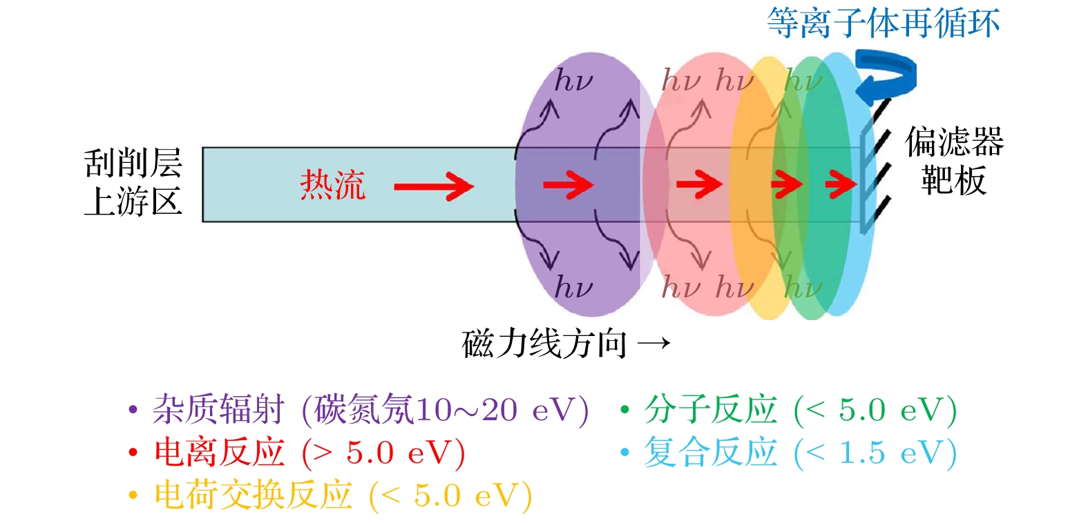
图 2 刮削层-偏滤器区域等离子体热流通道(沿磁力线方向)与主要反应
Fig. 2. Heat flux flowing along the field line and the main reactions in scrape-off layer (SOL) and divertor region.
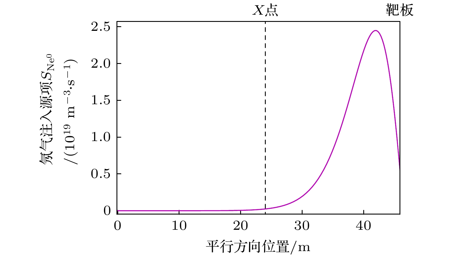
图 3 氖气注入偏滤器在沿磁力线方向形成的源剖面 $ {S}_{{{\mathrm{N}}{\mathrm{e}}}^{0}} $
Fig. 3. The source profile $ {S}_{{{\mathrm{N}}{\mathrm{e}}}^{0}} $ of neon injection into divertor
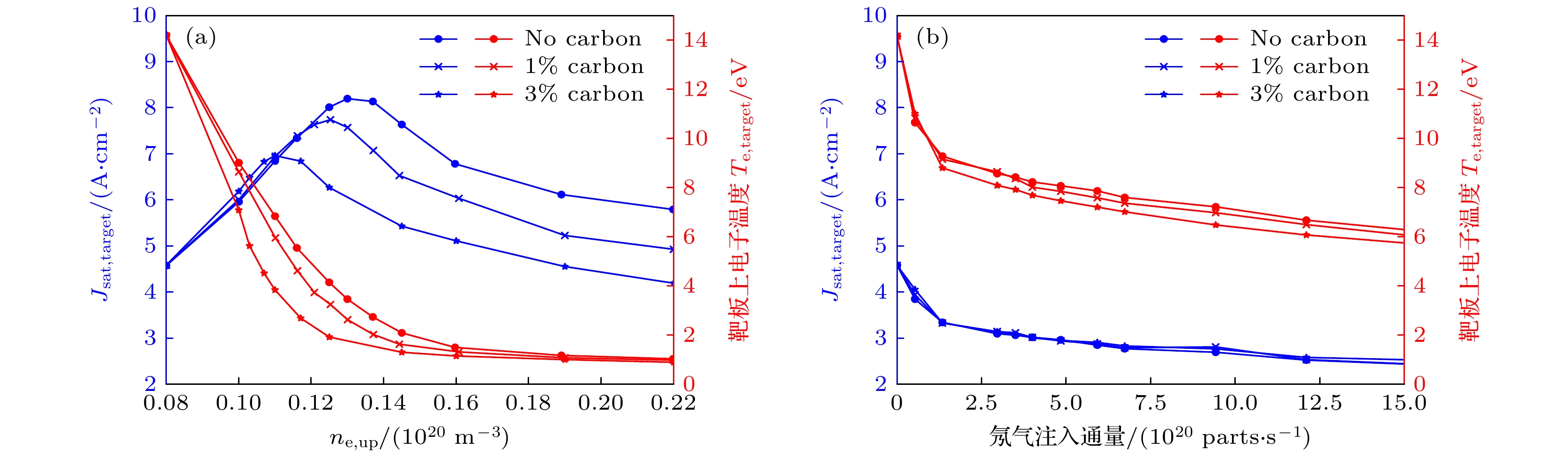
图 4 刮削层-偏滤器碳杂质含量的影响 (a)抬升上游等离子体密度触发偏滤器脱靶; (b)氖杂质注入偏滤器脱靶. 蓝色曲线表示靶板上电流$ {J}_{{\mathrm{s}}{\mathrm{a}}{\mathrm{t}}, {\mathrm{t}}{\mathrm{a}}{\mathrm{r}}{\mathrm{g}}{\mathrm{e}}{\mathrm{t}}} $, 红色曲线表示靶板上电子温度, 碳杂质含量$ {f}_{{\mathrm{C}}} $分别为0, 1%和3%
Fig. 4. The effect of carbon concentration in SOL and divertor region on two different divertor detachment regimes: (a) Density ramp induced detachment; (b) neon injection induced detachment. The blue curves and red curves represent the current and the electron temperature on the divertor target (three carbon concentrations used in simulations are 0, 1%, and 3%).
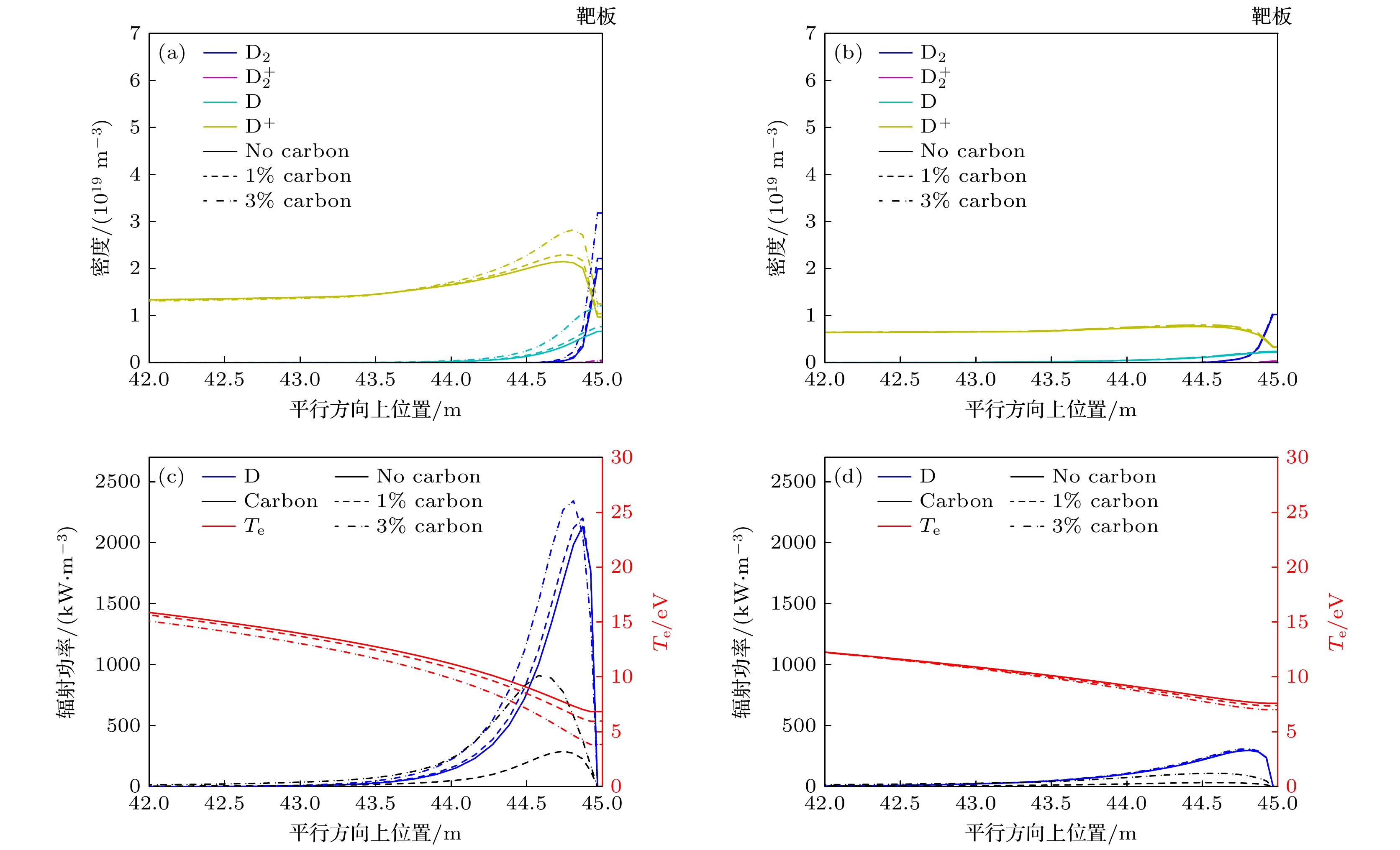
图 5 刮削层-偏滤器碳杂质含量($ {f}_{{\mathrm{C}}}=0, {\mathrm{ }}1{\mathrm{{\text{%}}}}{\mathrm{ }}, 3{\mathrm{{\text{%}}}} $)对平行方向上密度(氘分子、电离态氘分子、氘原子与氘离子)以及对辐射功率的影响 (a), (c)上游等离子体密度抬升至$ {n}_{{\mathrm{e}}, {\mathrm{u}}{\mathrm{p}}}={0.11\times 10}^{20}\;{{\mathrm{m}}}^{-3} $时的剖面; (b), (d) 氖杂质注入通量为$ {6.7\times 10}^{20}\;{\mathrm{p}}{\mathrm{a}}{\mathrm{r}}{\mathrm{t}}{\mathrm{s}}/{\mathrm{s}} $时的剖面, 靶板位于45 m处(由于氘粒子和碳杂质主要分布在靠近靶板的区域, 因此图中只给出了靠近靶板的平行剖面, 即42—45 m)
Fig. 5. The effect of carbon concentration (0, 1%, and 3%) on the parallel density and radiation profiles in two detachment regimes: (a), (c) The density and radiation in density ramp induced detachment ($ {n}_{{\mathrm{e}}, {\mathrm{u}}{\mathrm{p}}}={0.11\times 10}^{20}\;{{\mathrm{m}}}^{-3} $); (b), (d) the density and radiation in neon injection induced detachment (neon injection flux equal to $ {6.7\times 10}^{20}\;{\mathrm{p}}{\mathrm{a}}{\mathrm{r}}{\mathrm{t}}{\mathrm{s}}/{\mathrm{s}} $). The parallel profile is 42–45 m (the target located at 45 m).
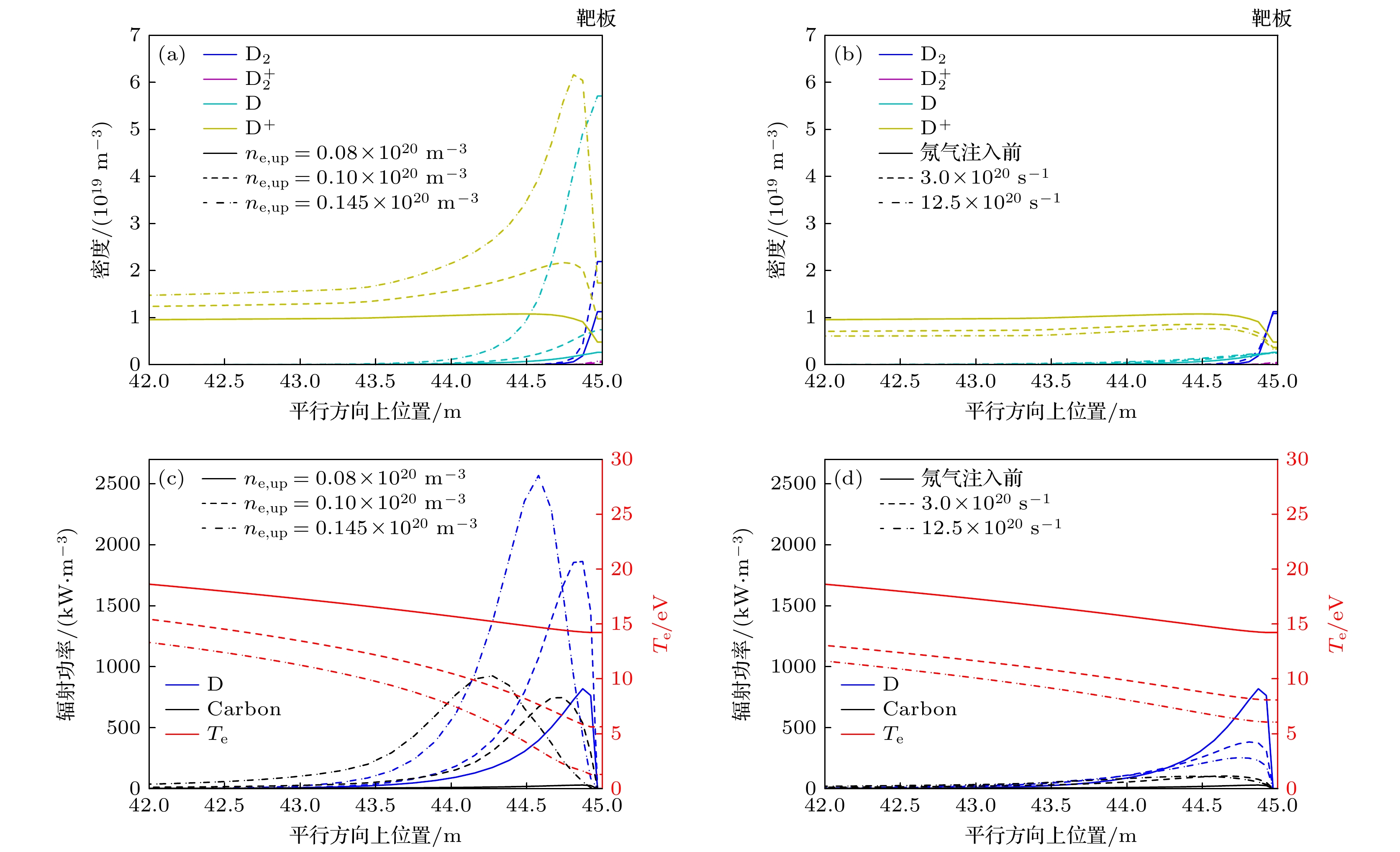
图 6 抬升密度和偏滤器氖杂质注入两种脱靶过程中的平行方向上密度(氘分子、电离态氘分子、氘原子与氘离子)以及辐射功率(氘与碳) (a), (c)刮削层上游电子密度在脱靶前$ {n}_{{\mathrm{e}}, {\mathrm{u}}{\mathrm{p}}}={0.08\times 10}^{20}\;{{\mathrm{m}}}^{-3} $、脱靶开始$ {n}_{{\mathrm{e}}, {\mathrm{u}}{\mathrm{p}}}={0.10\times 10}^{20}\;{{\mathrm{m}}}^{-3} $与脱靶后$ {n}_{{\mathrm{e}}, {\mathrm{u}}{\mathrm{p}}}=0.145\times $$ 10^{20}\;{{\mathrm{m}}}^{-3} $时的剖面; (b), (d)氖杂质注入前, 以及杂质注入通量为$ {3.0\times 10}^{20}\;{\mathrm{p}}{\mathrm{a}}{\mathrm{r}}{\mathrm{t}}{\mathrm{s}}/{\mathrm{s}} $, $ {12.5\times 10}^{20}\;{\mathrm{p}}{\mathrm{a}}{\mathrm{r}}{\mathrm{t}}{\mathrm{s}}/{\mathrm{s}} $时的剖面, 图中碳杂质含量都为3%, 靶板位于45 m处 (由于氘粒子和碳杂质主要分布在靠近靶板的区域, 图中只给出了靠近靶板的剖面, 即42—45 m)
Fig. 6. Comparison of the parallel density and radiation profiles in two detachment regimes: (a), (c) The density and radiation in density ramp induced detachment ($ {n}_{{\mathrm{e}}, {\mathrm{u}}{\mathrm{p}}}={0.08\times 10}^{20}\;{{\mathrm{m}}}^{-3} $, $ {0.10\times 10}^{20}\;{{\mathrm{m}}}^{-3}, $ and $ {0.145\times 10}^{20}\;{{\mathrm{m}}}^{-3} $); (b), (d) the density and radiation in neon injection induced detachment (neon injection flux equal to $ \text{0 parts/s} $, $ {3.0\times 10}^{20}\;{\mathrm{p}}{\mathrm{a}}{\mathrm{r}}{\mathrm{t}}{\mathrm{s}}/{\mathrm{s}}, $ and $ {12.5\times 10}^{20}\;{\mathrm{p}}{\mathrm{a}}{\mathrm{r}}{\mathrm{t}}{\mathrm{s}}/{\mathrm{s}} $), carbon concentration equal to 3%; the parallel profile is 42–45 m (the target located at 45 m).
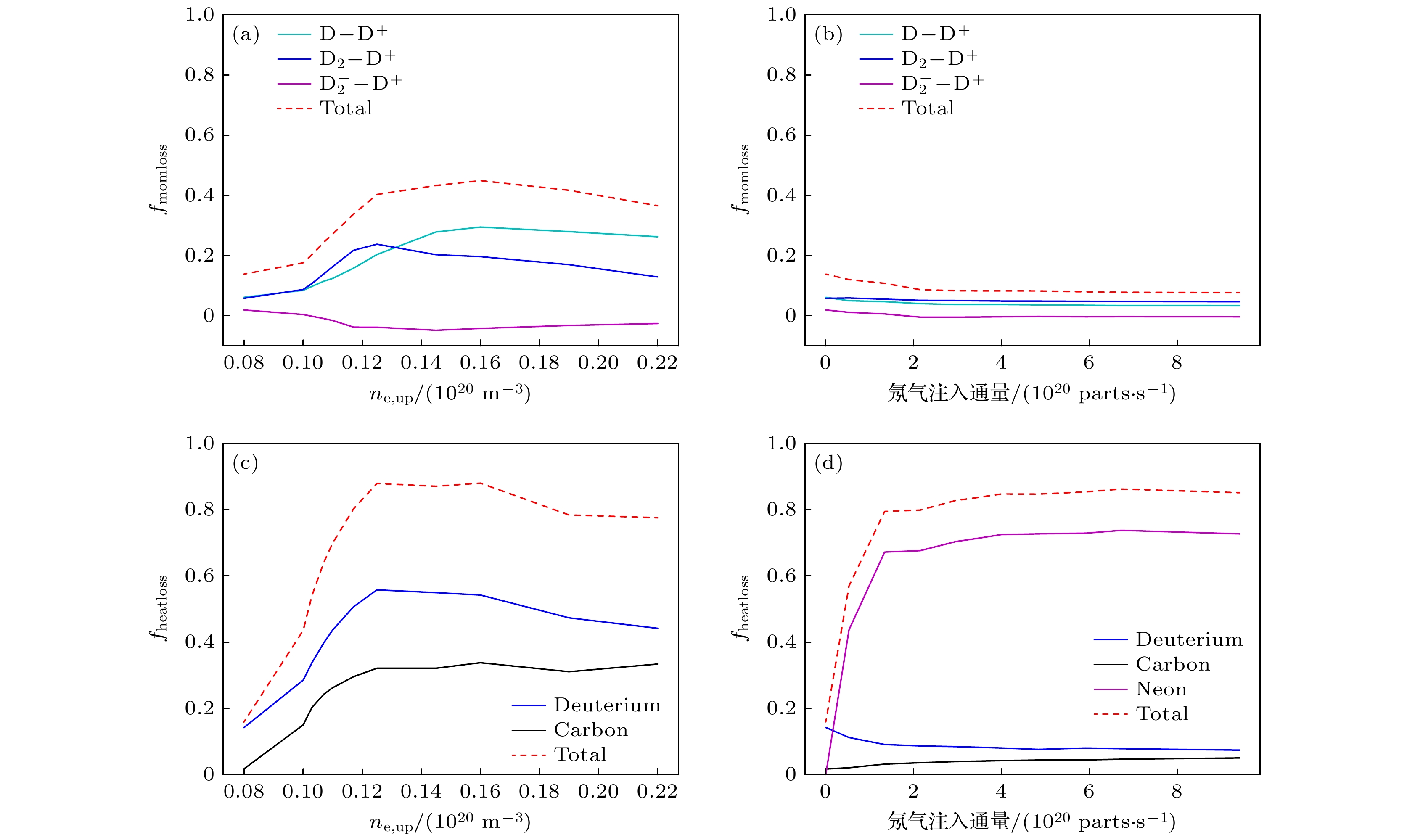
图 8 (a)上游密度抬升与(b)偏滤器注氖气两种脱靶过程中, 氘原子、氘分子、电离态氘分子与等离子体相互作用造成的等离子体动量损失与上游等离子体动量的比值, 即等离子体动量损失因子; (c)上游密度抬升与(d)偏滤器注氖气两种脱靶中, 氘粒子、碳杂质与氖杂质辐射造成的等离子体能量损失与上游等离子体能量的比值, 即等离子体能量损失因子, 碳含量为3%
Fig. 8. Momentum loss factor caused by different types of collisional reactions during (a) density ramp induced detachment and (b) neon injection induced detachment; heat loss factor caused by radiations of different particle species during (c) density ramp induced detachment and (d) neon injection induced detachment (carbon concentration equal to 3%).
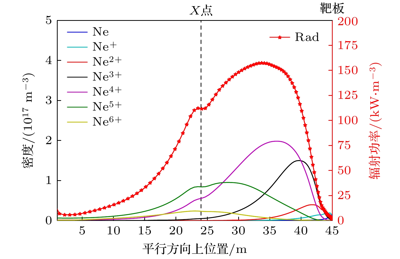
图 7 平行方向上从刮削层(0—24 m), 通过X点(24 m)氘靶板(45 m)的氖杂质密度和辐射功率(氖杂质注入通量为$ {3.0\times 10}^{20}\;{\mathrm{p}}{\mathrm{a}}{\mathrm{r}}{\mathrm{t}}{\mathrm{s}}/{\mathrm{s}} $, 上游电子密度$ {n}_{{\mathrm{e}}, {\mathrm{u}}{\mathrm{p}}}=0.08\times 10^{20}\;{{\mathrm{m}}}^{-3} $, 碳杂质含量为3%)
Fig. 7. Neon density and radiation profile along the parallel direction from SOL to the target (neon injection flux equal to $ {3.0\times 10}^{20}\;{\mathrm{p}}{\mathrm{a}}{\mathrm{r}}{\mathrm{t}}{\mathrm{s}}/{\mathrm{s}} $, $ {n}_{{\mathrm{e}}, {\mathrm{u}}{\mathrm{p}}}={0.08\times 10}^{20}\;{{\mathrm{m}}}^{-3} $, carbon concentration equal to 3%).
表 1 氘原子、氘分子的碰撞反应
Table 1. Collisional reactions of D and D2.
反应 名称 $ {\mathrm{e}}+{\mathrm{D}}\to 2{\mathrm{e}}+{{\mathrm{D}}}^{+} $ 电离 $ {{\mathrm{D}}}^{+}+{\mathrm{D}}\to {\mathrm{D}}+{{\mathrm{D}}}^{+} $ 电荷交换 $ {{\mathrm{D}}}^{+}+{\mathrm{e}}\to {\mathrm{D}} $ 复合 $ {\mathrm{e}}+{{\mathrm{D}}}_{2}\to 2{\mathrm{e}}+{{\mathrm{D}}}_{2}^{+} $ 分子电离 $ {\mathrm{e}}+{{\mathrm{D}}}_{2}\to {\mathrm{e}}+{\mathrm{D}}+{\mathrm{D}} $ 分解 $ {{\mathrm{D}}}^{+}+{{\mathrm{D}}}_{2}\to {{\mathrm{D}}}_{2}^{+}+{\mathrm{D}} $ 分子电荷交换 $ {\mathrm{e}}+{{\mathrm{D}}}_{2}^{+}\to {\mathrm{e}}+{{\mathrm{D}}}^{+} $+ $ {\mathrm{D}} $ 分解激发 $ {\mathrm{e}}+{{\mathrm{D}}}_{2}^{+}\to 2{\mathrm{e}}+{{\mathrm{D}}}^{+} $+ $ {{\mathrm{D}}}^{+} $ 分解电离 $ {\mathrm{e}}+{{\mathrm{D}}}_{2}^{+}\to $ $ {\mathrm{D}}+{\mathrm{D}} $ 分解复合  下载: 导出CSV
表 2 氖杂质的碰撞反应
Table 2. Collisional reaction of neon impurities.
反应 名称 $ {{\mathrm{N}}{\mathrm{e}}}^{{{Z}}+}+{\mathrm{e}}\to {{\mathrm{N}}{\mathrm{e}}}^{Z+1}+2{\mathrm{e}} $ 电离 ($ Z $ = 0—9) $ {{\mathrm{N}}{\mathrm{e}}}^{{{Z}}+}+{\mathrm{e}}\to {{\mathrm{N}}{\mathrm{e}}}^{Z-1} $ 复合 ($ Z $ = 1—10) $ {{\mathrm{N}}{\mathrm{e}}}^{{{Z}}+}+{\mathrm{D}}\to {{\mathrm{N}}{\mathrm{e}}}^{Z-1}+{{\mathrm{D}}}^{+} $ 电荷交换 ($ Z $ = 1—10)
下载: 导出CSV
表 3 SD1D主要输入参数
Table 3. The input parameters of SD1D.
$ {n}_{\rm e,up}/({10}^{20}~{\rm m}^{-3})$ 氖气注入通量/(1020 part·s–1) Qheat,up/(MW·m–2) 总连接长度/m X点到靶板连接长度/m 密度抬升脱靶 0.08—0.22 无 7.2 45 21 氖杂质注入脱靶 0.8 0—15.0 7.2 45 21
下载: 导出CSV
-
[1] Stangeby P C 2000 The Plasma Boundary of Magnetic Fusion Devices (CRC Press
[2] Kallenbach A, Bernert M, Dux R, Reimold F, Wischmeier M, ASDEX Upgrade Team 2016 Plasma Phys. Contr. Fusion 58 045013
Google Scholar
[3] Stangeby P C 2018 Plasma Phys. Contr. Fusion 60 044022
Google Scholar
[4] Verhaegh K, Lipschultz B, Bowman C, Duval B P, Fantz U, Fil A, Harrison J R, Moulton D, Myatra O, Wünderlich D, Federici F 2021 Plasma Phys. Contr. Fusion 63 035018
Google Scholar
[5] Kunze H J 2009 Springer Science & Business Media 56 34
[6] Bernert M, Wischmeier M, Huber A, Reimold F, Lipschultz B, Lowry C, Brezinsek S, Dux R, Eich T, Kallenbach A, Lebschy A 2017 Nucl. Mater. Energy 12 111
Google Scholar
[7] Wu T, Nie L, Yu Y, Gao J M, Li J Y, Ma H C, Wen J, Ke R, Wu N, Huang Z H, Liu L, Zheng D L, Yi K Y, Gao X Y, Wang W C, Cheng J, Yan L W, Cai L Z, Wang Z H, Xu M 2023 Plasma Sci. Tech. 25 015102
Google Scholar
[8] Zhou Y, Dudson B, Militello F, Verhaegh K, Myatra O 2022 Plasma Phys. Contr. Fusion 64 065006.
Google Scholar
[9] Boedo J, Gray D, Chousal L, Conn R, Hiller B, Finken K. H 1998 Rev. Sci. Instrum. 69 2663
Google Scholar
[10] Boedo J A, Crocker N, Chousal L, Hernandez R, Chalfant J, Kugel H, Roney P, Wertenbaker J, NSTX Team 2009 Rev. Sci. Instrum. 80 123506
Google Scholar
[11] Clark J G, Bowden M D, Scannell R 2021 Rev. Sci. Instrum. 92 043545
Google Scholar
[12] Makarov S O, Coster D P, Kaveeva E G, Rozhansky V A, Senichenkov I Y, Veselova I Y, Voskoboynikov S P, Stepanenko A A, Bonnin X, Pitts R A 2023 Nucl. Fusion 63 026014.
Google Scholar
[13] Mailloux J, Abid N, Abraham K, Abreu P, Adabonyan O, Adrich P, Afanasev V, Afzal M, Ahlgren T, Aho-Mantila L, Aiba N 2022 Nucl. Fusion 62 042026
Google Scholar
[14] Fil A, Lipschultz B, Moulton D, Thornton A, Dudson B D, Myatra O, Verhaegh K, EUROfusion MST1 Team 2022 Nucl. Fusion 62 096026
Google Scholar
[15] Myatra O, Moulton D, Dudson B, Lipschultz B, Newton S, Verhaegh K, Fil A 2023 Nucl. Fusion 63 076030
Google Scholar
[16] Verhaegh K, Lipschultz B, Duval B P, Harrison J R, Reimerdes H, Theiler C, Labit B, Maurizio R, Marini C, Nespoli F, Sheikh U 2017 Nucl. Mater. Energy 12 1112.
Google Scholar
[17] Gao J M, Cai L Z, Cao C Z, Ma H C, Ke R, Wu N, Hu Y, Gao X Y, Cui C H, Huang Z H, Nie L 2023 Nucl. Fusion 63 036006
Google Scholar
[18] 龙婷, 柯锐, 吴婷, 高金明, 才来中, 王占辉, 许敏 2024 . 73 088901
Google Scholar
Long T, Ke R, Wu T, Gao J M, Cai L Z, Wang Z H, Xu M, 2024 Acta Phys. Sin. 73 088901
Google Scholar
[19] Wu N, Cheng J, Yi K Y, Wang R, Han M K, Huang Z H, Wang W C, He Y, Yan L W, Du H L, Gao J M 2024 Nucl. Fusion 64 096007
Google Scholar
[20] Liu J B, Wang L, Guo H Y, Wang H Q, Xu G S, Ding F, Xu J C, Liu X J, Yuan Q P, Wu K, Liu S C 2019 Nucl. Fusion 59 126046
Google Scholar
[21] Dudson B. D, Allen J, Body T, Chapman B, Lau C, Townley L, Moulton D, Harrison J, Lipschultz B 2019 Plasma Phys. Contr. Fusion 61 065008
Google Scholar
[22] Kallenbach A, Bernert M, Dux R, Eich T, Henderson S S, Pütterich T, Reimold F, Rohde V, Sun H J, ASDEX Upgrade Team 2019 Nucl. Mater. Energy 18 166
Google Scholar
[23] Zhou Y, Dudson B, Wu T, Wang Z, Xia T, Zhong C, Gao J, Du H, Fan D 2024 Plasma Phys. Contr. Fusion 66 055005
Google Scholar

 下载:
下载:


计量
- 文章访问数: 796
- PDF下载量: 25
- 被引次数: 0
