-
Dielectrophoresis affects the surface wettability by applying a non-uniform electric field to dipoles inside dielectric liquid, achieving adjustable droplet contact angle and overcoming the saturation limitation of contact angle caused by the electrowettability effect. However, it is difficult to realize useful three-dimensional tunable optical devices because most of the driving electrodes need to be patterned. In this work, a model of double flexible electrodes simulating planar interdigitated pattern electrodes is proposed based on the dielectrophoresis. Double flexible electrodes, which are wrapped with an insulating dielectric layer and are not conductive to each other are arranged at close intervals and wound along the plane substrate to form a two-dimensional planar line wall. A hydrophobic layer is used to fill the gap and increase the initial contact angle. Ultimately, the “droplet-interdigitated planar line wall” dielectrophoresis driven-droplet model is formed after the dielectric droplets have been deposited on the line wall surface. Firstly, considering the influence of penetration depth and electrode gap area, Young’s equation is theoretically modified to adapt to this model. Then, the finite element algorithm simulation is used to used to comparatively analyze the potential distribution of this model and the planar interdigitated pattern electrode model. The field strength distributions of the electrodes with different wire diameters and insulating layer thickness values are analyzed. It can be found that with the increase of the diameter of the electrode wire and the thickness of the insulating layer, the morphology of the model changes from the tip electrode into the planar electrode, the surface field strength attenuates exponentially and the peak value decreases. This shows that the structure of this electrode in this model is superior to that of the planar electrode. After that, the contact angle of the model is measured experimentally in a range of 58°-90° under 0–250 Vrms voltage, which is in line with the theoretical expectation. At the same time, neither obvious contact angle lag nor saturation is observed in the experiment. Finally, the new electrophoretic driving droplet model constructed in this paper transforms the dielectric electrophoretic driving mode from a two-dimensional planar electrode to a one-dimensional flexible linear electrode. Because of its flexibility and plasticity, it is convenient to form a three-dimensional cavity and can be applied to more complex device structures.
-
Keywords:
- dielectrophoresis /
- simulated interdigitated patterned electrodes /
- flexible electrodes /
- contact angle
[1] McHale G, Brown, C V, Newton M I, Wells G G, Sampara N 2011 Phys. Rev. Lett. 107 186101
 Google Scholar
[2] Huhtamäki T, Tian X, Korhonen J T, Ras R H 2018 Nat. Protoc. 13 1521
 Google Scholar
[3] Armstrong S, McHale G, Ledesma-Aguilar R, Wells G G 2020 Langmuir 36 11332
 Google Scholar
[4] Kedzierski J, Holihan E 2018 Sci. Robot 3 eaat5643
 Google Scholar
[5] Renaudot R, Daunay B, Kumemura M, Agache V, Jalabert L, Collard D, Fujita H 2013 Sens. Actuat. B Chem. 177 620
 Google Scholar
[6] Quinn A, Sedev R, Ralston J 2005 J. Phys. Chem. B 109 6268
 Google Scholar
[7] Frozanpoor I, Cooke M D, Ambukan V, Gallant A J, Balocco C 2021 Langmuir 37 6414
 Google Scholar
[8] Mahani M A, Karimvand A N, Naserifar N 2023 J. Sep. Sci. 46 2300257
 Google Scholar
[9] Jiang L X, Liang F, Huo M X, Ju M Q, Xu J, Ju S, Xu J J, Ju S W, Jin L H, Shen B J 2023 Microelectron. Eng. 282 112100
 Google Scholar
[10] Huang K, Lu B, Lai J, Chu H K H 2019 IEEE Trans. Biomed. Circuits Syst. 13 1063
 Google Scholar
[11] Xu S, Ren H, Wu S T 2013 J. Phys. D Appl. Phys. 46 483001
 Google Scholar
[12] Xu S, Lin Y J, Wu S T 2009 Opt. Express 17 10499
 Google Scholar
[13] Zhang Z, Li L, Liu X, Li L, Li Y 2023 Opt. Lasers Eng. 163 107450
 Google Scholar
[14] Frozanpoor I, Cooke M, Racz Z, Bossons I, Ambukan V, Wood D, Gallant A, Balocco C 2021 J. Micromech. Microeng. 31 055014
 Google Scholar
[15] Li X, Duan J, Qu Z, Wang J, Ji M, Zhang B 2022 Micromachines 13 117.
 Google Scholar
[16] Chen Q, Li T, Zhu Y, Yu W, Zhang X 2018 Opt. Express 26 6532.
 Google Scholar
[17] Lu Y S, Tu H, Xu Y, Jiang H 2013 Appl. Phys. Lett. 103 261113
 Google Scholar
[18] Shahini A, Xia J, Zhou Z, Zhao Y, Cheng M M C 2016 Langmuir 32 1658
 Google Scholar
[19] Almoallem Y D, Jiang H 2017 J. Microelectromech. Syst 26 1122
 Google Scholar
[20] Nakano M, Inaba M, Murakami T, Sakurai M, Suehiro J 2023 IEEE Sens. Lett. 7 1
 Google Scholar
[21] Edwards A M, Brown C V, Newton M I, McHale G 2018 Curr. Opin. Colloid Interface Sci. 36 28
 Google Scholar
[22] Yi U C, Kim C J 2006 J. Micromech. Microeng. 16 2053
 Google Scholar
-
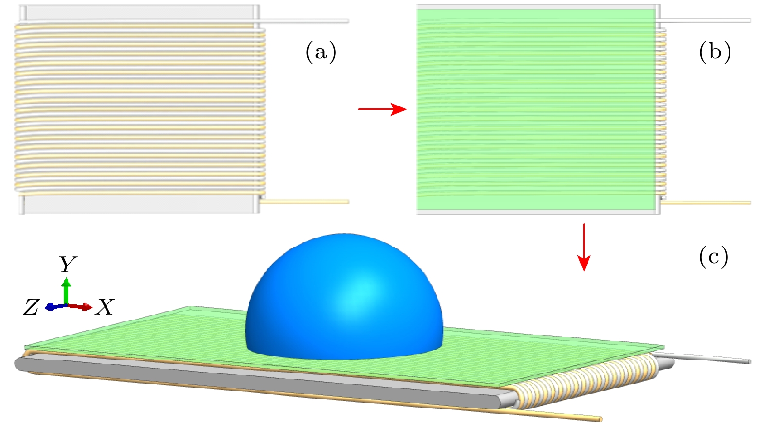
图 1 基于双柔性线性电极构造的“液滴-叉指平面线墙”模型 (a)双柔性电极线墙排布; (b)疏水层涂覆; (c) “液滴-叉指平面线墙”模型
Fig. 1. The “droplet-interdigitated planar line wall” model based on double flexible linear electrodes: (a) Double flexible electrode wire wall arrangement; (b) coating hydrophobic layer; (c) the “droplet-interdigitated planar line wall” model.
图 5 液滴接触角及余弦差值关系图 (a)液滴前进及后退接触角与理论接触角对比; (b)接触角余弦差值拟合
Fig. 5. Schematic diagram of droplet contact angle and cosine difference diagram: (a) The comparison between the forward and backward contact angle of the droplet and the theoretical contact angle; (b) the fitting of the contact angle cosine difference.
-
[1] McHale G, Brown, C V, Newton M I, Wells G G, Sampara N 2011 Phys. Rev. Lett. 107 186101
 Google Scholar
[2] Huhtamäki T, Tian X, Korhonen J T, Ras R H 2018 Nat. Protoc. 13 1521
 Google Scholar
[3] Armstrong S, McHale G, Ledesma-Aguilar R, Wells G G 2020 Langmuir 36 11332
 Google Scholar
[4] Kedzierski J, Holihan E 2018 Sci. Robot 3 eaat5643
 Google Scholar
[5] Renaudot R, Daunay B, Kumemura M, Agache V, Jalabert L, Collard D, Fujita H 2013 Sens. Actuat. B Chem. 177 620
 Google Scholar
[6] Quinn A, Sedev R, Ralston J 2005 J. Phys. Chem. B 109 6268
 Google Scholar
[7] Frozanpoor I, Cooke M D, Ambukan V, Gallant A J, Balocco C 2021 Langmuir 37 6414
 Google Scholar
[8] Mahani M A, Karimvand A N, Naserifar N 2023 J. Sep. Sci. 46 2300257
 Google Scholar
[9] Jiang L X, Liang F, Huo M X, Ju M Q, Xu J, Ju S, Xu J J, Ju S W, Jin L H, Shen B J 2023 Microelectron. Eng. 282 112100
 Google Scholar
[10] Huang K, Lu B, Lai J, Chu H K H 2019 IEEE Trans. Biomed. Circuits Syst. 13 1063
 Google Scholar
[11] Xu S, Ren H, Wu S T 2013 J. Phys. D Appl. Phys. 46 483001
 Google Scholar
[12] Xu S, Lin Y J, Wu S T 2009 Opt. Express 17 10499
 Google Scholar
[13] Zhang Z, Li L, Liu X, Li L, Li Y 2023 Opt. Lasers Eng. 163 107450
 Google Scholar
[14] Frozanpoor I, Cooke M, Racz Z, Bossons I, Ambukan V, Wood D, Gallant A, Balocco C 2021 J. Micromech. Microeng. 31 055014
 Google Scholar
[15] Li X, Duan J, Qu Z, Wang J, Ji M, Zhang B 2022 Micromachines 13 117.
 Google Scholar
[16] Chen Q, Li T, Zhu Y, Yu W, Zhang X 2018 Opt. Express 26 6532.
 Google Scholar
[17] Lu Y S, Tu H, Xu Y, Jiang H 2013 Appl. Phys. Lett. 103 261113
 Google Scholar
[18] Shahini A, Xia J, Zhou Z, Zhao Y, Cheng M M C 2016 Langmuir 32 1658
 Google Scholar
[19] Almoallem Y D, Jiang H 2017 J. Microelectromech. Syst 26 1122
 Google Scholar
[20] Nakano M, Inaba M, Murakami T, Sakurai M, Suehiro J 2023 IEEE Sens. Lett. 7 1
 Google Scholar
[21] Edwards A M, Brown C V, Newton M I, McHale G 2018 Curr. Opin. Colloid Interface Sci. 36 28
 Google Scholar
[22] Yi U C, Kim C J 2006 J. Micromech. Microeng. 16 2053
 Google Scholar
计量
- 文章访问数: 5324
- PDF下载量: 213
- 被引次数: 0


 下载:
下载:


