


-
偶极磁场约束等离子体特性及其与带电粒子束的相互作用研究是近地空间磁层等离子体研究领域关心的一类重要问题. 本研究采用粒子模拟(particle in cell, PIC)方法, 通过开源的Smilei程序, 研究了电子束注入偶极磁场约束等离子体的三维动力学演化行为. 模拟了不同注入角度电子束对等离子体的影响, 给出了电子束及等离子体的时空演化过程和行为解释. 结果显示, 偶极磁场中的等离子体沿磁场线形成“新月形”壳结构分布, 壳中形成内外相反方向的环形电流. 当电子束的注入角度与磁场方向的夹角过大(超过20°), 且漂移速度方向未对准偶极场中心时, 大多数电子束粒子将在偶极磁场中漂移, 散射并弹出模拟区域, 无法与偶极磁场约束的等离子体发生相互作用. 未来我国的偶极磁场约束等离子体研究装置在开展电子束与等离子体相互作用的实验时, 有必要选择适当的电子束入射方向, 以确保电子束能够进入偶极磁场的核心区域并与原来约束的等离子体进行相互作用. 同时模拟结果显示电子束注入会使得等离子体环形电流在环向上变得不均匀. 本研究有助于深入了解偶极磁场中的等离子体动力学行为特性, 对于保障我国空间等离子体研究装置完成预期科学目标具有实际价值.
Research into the characteristics of dipole magnetic field-confined plasmas and their interaction with charged particle beams is critical for understanding near-Earth magnetospheric plasma. In this paper, a fully relativistic electromagnetic particle-in-cell (PIC) method, implemented with the open-source code Smilei, is used to perform three-dimensional kinetic simulations of the evolution of electron beams injected into the dipole magnetic field confined plasmas. The simulation adopts a uniform grid with 256 cells in each spatial direction, neglects collisional effects, and considers a plasma consisting only of electrons and ions. The initial plasma with a number density of 1×10¹² m–3 is configured as a rectangular toroidal structure with a square cross-section. An externally prescribed dipole magnetic field is applied to the simulation domain. This field is generated by an ideal current loop centered in the grid’s x-y plane, with a loop radius of 1/8 the grid length a current magnitude of 4000 A, and a maximum magnetic field strength of 6000 G. Under these conditions, the ratio of electron plasma frequency to gyrofrequency ranges from 5.3×10⁻⁴ to 3.2, and the plasma beta varies from 2.24×10⁻¹⁰ to 8×10⁻³. The grid cell size is set to 0.05 times the electron Debye length, and the time step is 0.95 times the CFL time step. The simulation runs for a total of 20000 steps to achieve a quasi-steady state. The electron beams with a temperature of 10 eV and a drift velocity of 1×10⁷ m/s are injected from the x-min boundary of the grid at angles of 0°, 30°, and 60° relative to the positive x-axis, to explore the influence of electron beams with varying injection angles on the dipole magnetic field confined plasma. The simulation results demonstrate the spatiotemporal evolution and behavior of the electron beam and plasma. Specifically, the plasma confined by a dipole magnetic field forms a crescent-shaped shell structure that aligns with magnetic field lines, with toroidal currents of opposite directions generated inside and outside the shell. When the electron beam is injected at incident angles of 0° and 30°, drift effects cause most of beam particles to concentrate along a specific magnetic field line on the $ x+y=250\Delta x $ plane. Additionally, the drift current induced by electron beam injection changes the distribution of the central toroidal current in the main plasma, resulting in localized enhancement and attenuation of the toroidal current. In contrast, at an injection angle of 60°, the vast majority of beam particles are scattered by the dipole magnetic field, and fail to reach the central region to interact with the main plasma. Simulation findings further indicate that when the electron beam’s injection angle relative to the magnetic field direction exceeds 20° and its drift velocity is misaligned with the dipole field center, most of beam particles scatter and are ejected from the simulation domain, precluding interaction with the dipole-confined plasma. For future experimental devices studying the interactions between electron beam and plasma in dipole magnetic field confinement systems, choosing an appropriate beam injection direction is critical to ensure that the electrons can reach the core region of the dipole field and interact with the confined plasma. This study offers valuable insights into the dynamic behavior of plasma in dipole magnetic fields, aiding space plasma research facilities in achieving their designed scientific objectives. 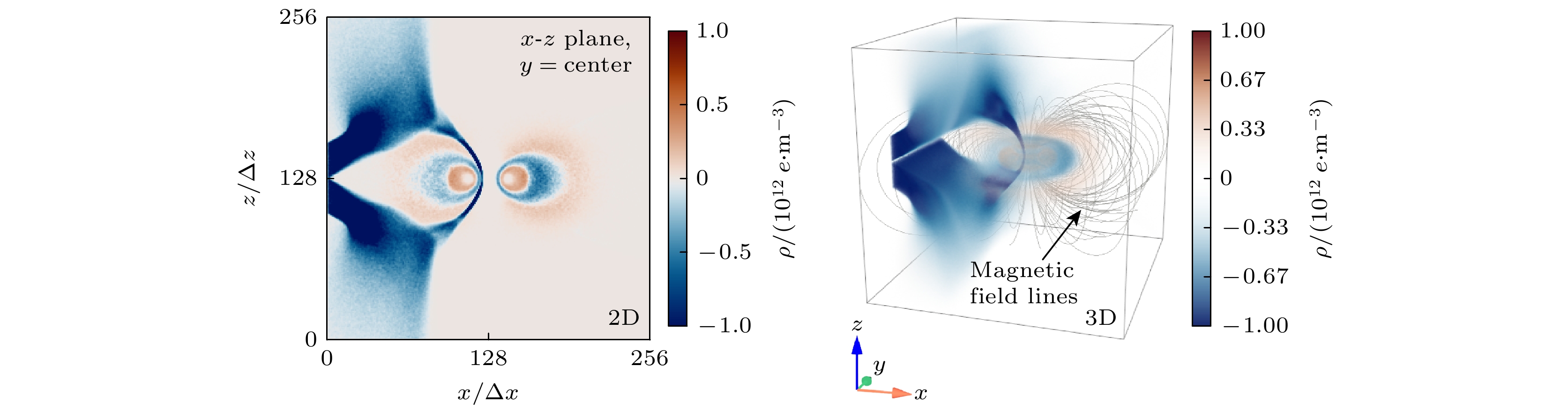
-
Keywords:
- plasma /
- electron beam /
- dipole magnetic field /
- particle-in-cell
[1] Levitt B, Maslovsky D, Mauel M E 2005 Phys. Rev. Lett. 94 175002
 Google Scholar
[2] Baitha A R, Kumar A, Bhattacharjee S 2018 Rev. Sci. Instrum. 89 23503
Google Scholar
[3] Saitoh H, Yoshida Z, Morikawa J, Yano Y, Hayashi H, Mizushima T, Kawai Y, Kobayashi M, Mikami H 2010 Phys. Plasmas 17 112111
Google Scholar
[4] 王敬之, 马新, 项正, 顾旭东, 焦鹿怀, 雷良建, 倪彬彬 2022 71 229401
Google Scholar
Wang Z J, Ma X, Xiang Z, Gu X D, Jiao L H, Lei L J, Ni B B 2022 Acta Phys. Sin. 71 229401
Google Scholar
[5] 朱琪, 马新, 曹兴, 倪彬彬, 项正, 付松, 顾旭东, 张援农 2022 71 051101
Google Scholar
Zhu Q, Ma X, Cao X, Ni B B, Xiang Z, Fu S, Gu X D, Zhang Y N 2022 Acta Phys. Sin. 71 051101
Google Scholar
[6] 常珊珊, 倪彬彬, 赵正予, 汪枫, 李金星, 赵晶晶, 顾旭东, 周晨 2014 63 069401
Google Scholar
Chang S S, Ni B B, Zhao Z Y, Wang F, Li J X, Zhao J J, Gu X D, Zhou C 2014 Acta Phys. Sin. 63 069401
Google Scholar
[7] 倪彬彬, 赵正予, 顾旭东, 汪枫 2008 57 7937
Google Scholar
Ni B B, Zhao Z Y, Gu X D, Wang F 2008 Acta Phys. Sin. 57 7937
Google Scholar
[8] 顾旭东, 赵正予, 倪彬彬, 王翔, 邓峰 2008 57 6673
Google Scholar
Gu X D, Zhao Z Y, Ni B B, Wang X, Deng F 2008 Acta Phys. Sin. 57 6673
Google Scholar
[9] Korotova G I, Sibeck D G, Tahakashi K, Dai L, Spence H E, Kletzing C A, Wygant J R, Manweiler J W, Moya P S, Hwang K J, Redmon R J 2015 Ann. Geophys. 33 955
Google Scholar
[10] Zong Q G, Hao Y Q, Wang Y F 2009 Sci. China Ser. E-Technol. Sci. 52 3698
Google Scholar
[11] Zong Q G, Wang Y F, Yang B, Fu S Y, Pu Z Y, Xie L, Fritz T A 2008 Sci. China Ser. E-Technol. Sci. 51 1620
Google Scholar
[12] Van Compernolle B, An X, Bortnik J, Thorne R M, Pribyl P, Gekelman W 2015 Phys. Rev. Lett. 114 245002
Google Scholar
[13] Chen J, Powis A T, Kaganovich I D, Wang Z B, Yu Y 2025 Phys. Rev. Lett. 135 45301
Google Scholar
[14] Nishio K, Mori K, Alpert H S 2025 AIAA Scitech Forum AIAA 2025
[15] Huang H, Wang Z B, Wang X G, Tao X 2018 Chin. Phys. B 27 015201
Google Scholar
[16] Huang H, Wang Z B, Wang X G, Tao X. 2019 Phys. Plasmas 26 022106
Google Scholar
[17] Xiao Q M, Wang Z B, Wang X G, Xiao C J, Yang X Y, Zheng J X 2017 Plasma Sci. Technol. 19 35301
Google Scholar
[18] 刘腾, 张国书, 杜俊杰, 杨庆喜, 黄淑龙, 刘云辉 2022 核聚变与等离子体物理 42 271
Liu T, Zhang G S, Du J J, Yang Q X, Huang S L, Liu Y H 2022 Nucl. Fusion Plasma Phys. 42 271
[19] 孙玄, 刘明, 谢锦林, 余羿, 林木楠, 张情 2014 中国科学技术大学学报 44 374
Sun X, Liu M, Xie J L, Yu Y, Lin M N, Zhang Q 2014 J. Univ. Sci. Technol. China 44 374
[20] Xiao C J, Chen Y H, Yang X Y, Xu T C, Wang L, Xu M, Guo D, Yu Y, Lin C 2016 Rev. Sci. Instrum. 87 11D610
Google Scholar
[21] Sun C J, Sang C F, Ye H, Wang Q, Liu H, Wang Z H, Wang H J, Ke R, Wang Y, Zhang Y J, Wang D Z 2021 Fusion Eng. Des. 162 112074
Google Scholar
[22] 王志斌, 沈炀, 余羿, 陈坚 2024 南方能源建设 11 1
Wang Z B, Shen Y, Yu Y, Chen J 2024 Southern Energy Construction 11 1
[23] Zhukovsky A, Michael P C, Schultz J H, Smith B A, Minervini J V, Kesner J, Radovinsky A, Garnier D, Mauel M 2005 Fusion Eng. Des. 75–79 29
[24] Saitoh H, Yoshida Z, Morikawa J, Furukawa M, Yano Y, Kawai Y, Kobayashi M, Vogel G, Mikami H 2011 Phys. Plasmas 18 056102
Google Scholar
[25] Barnes C W, Jarboe T R, Henins I, Sherwood A R, Knox S O, Gribble R, Hoida H W, Klingner P L, Lilliequist C G, Linford R K, Platts D A, Spencer R L, Tuszewski M 1984 Nucl. Fusion 24 267
Google Scholar
[26] Yoshida Z, Ogawa Y, Morikawa J, Watanabe S, Yano Y, Mizumaki S, Tosaka T, Ohtani Y, Hayakawa A, Shibui M 2006 Plasma Fusion Res. 1 8
Google Scholar
[27] von der Linden J, Nissl S, Deller A, Singer M, Belmore N, Hugenschmidt C P, Pedersen T S, Saitoh H, Stenson E V 2024 Eur. Phys. J. D 78 146
Google Scholar
[28] Deller A, von der Linden J, Ni Ss L S, Michishio K, Oshima N, Higaki H, Stenson E V 2024 Phys. Rev. E 110 L23201
[29] Derouillat J, Beck A, Pérez F, Vinci T, Chiaramello M, Grassi A, Flé M, Bouchard G, Plotnikov I, Aunai N, Dargent J, Riconda C, Grech M 2018 Comput. Phys. Commun. 222 351
Google Scholar
[30] Sun J, Gao X, Chen L, Lu Q, Tao X, Wang S 2016 Phys. Plasmas 23 22901
Google Scholar
[31] Ortner M, Bandeira L G C 2020 SoftwareX 11 100466
Google Scholar
-
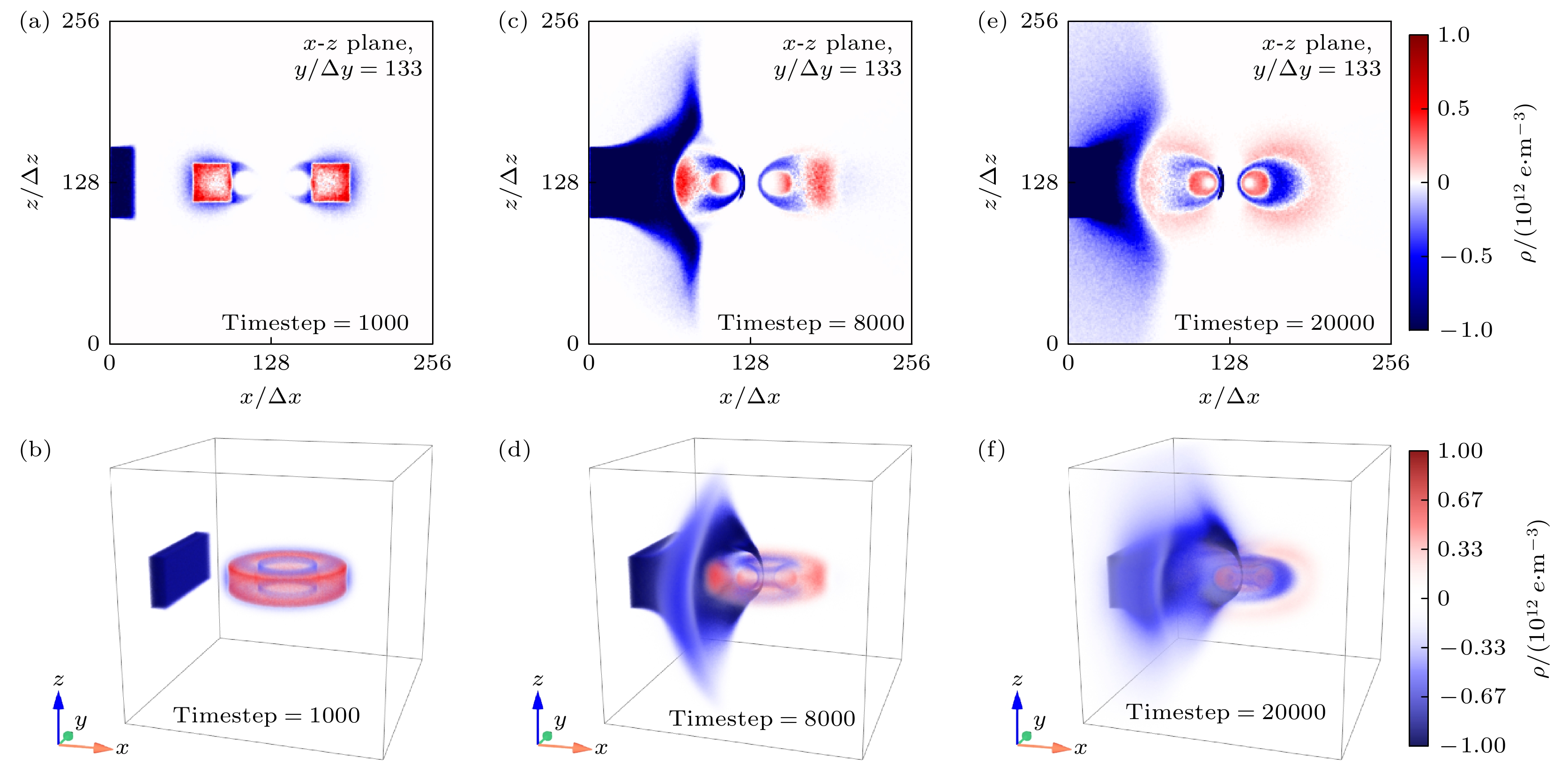
图 2 注入角度为0°的电子束作用下等离子体的电荷密度分布 (a), (c), (e)分别为1000步、8000步和20000步时刻的二维分布; (b), (d), (f)分别为1000步、8000步和20000步时刻的三维分布
Fig. 2. Charge number density distribution of the plasma under beam injection with an injection angle of 0°: (a), (c), (e) Two-dimensional distributions at 1000 steps, 8000 steps, and 20000 steps, respectively; (b), (d), (f) three-dimensional distributions at 1000 steps, 8000 steps, and 20000 steps, respectively.
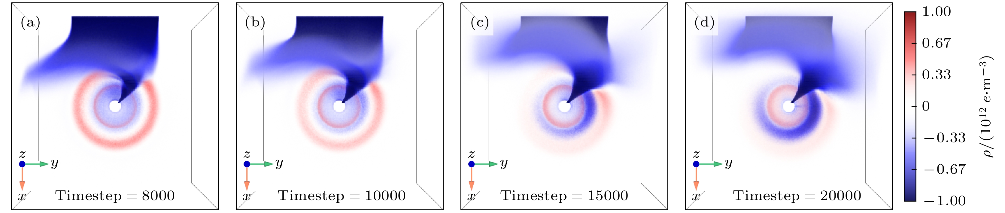
图 3 注入角度为0°的电子束作用下不同时刻的三维电荷密度分布俯视图 (a) t = 8000Δt; (b) t = 10000Δt; (c) t = 15000Δt; (d) t = 20000Δt
Fig. 3. Top view of the three-dimensional charge number density distribution at different moments under beam injection with an injection angle of 0°: (a)t = 8000Δt; (b) t = 10000Δt; (c) t = 15000Δt; (d) t = 20000Δt.
图 4 注入角度为0°的电子束作用下不同时间步长网格对角线平面($ x+y=256\Delta x $平面)处扰动磁场的流线和分布 (a) t = 1000Δt; (b) t = 5000Δt; (c) t = 8000Δt; (d) t = 20000Δt
Fig. 4. Streamlines and distributions of the disturbed magnetic field on the grid diagonal plane ($ x+y=256\Delta x $ plane) with 0° injection angle at different time steps: (a) t = 1000Δt; (b) t = 5000Δt; (c) t = 8000Δt; (d) t = 20000Δt.
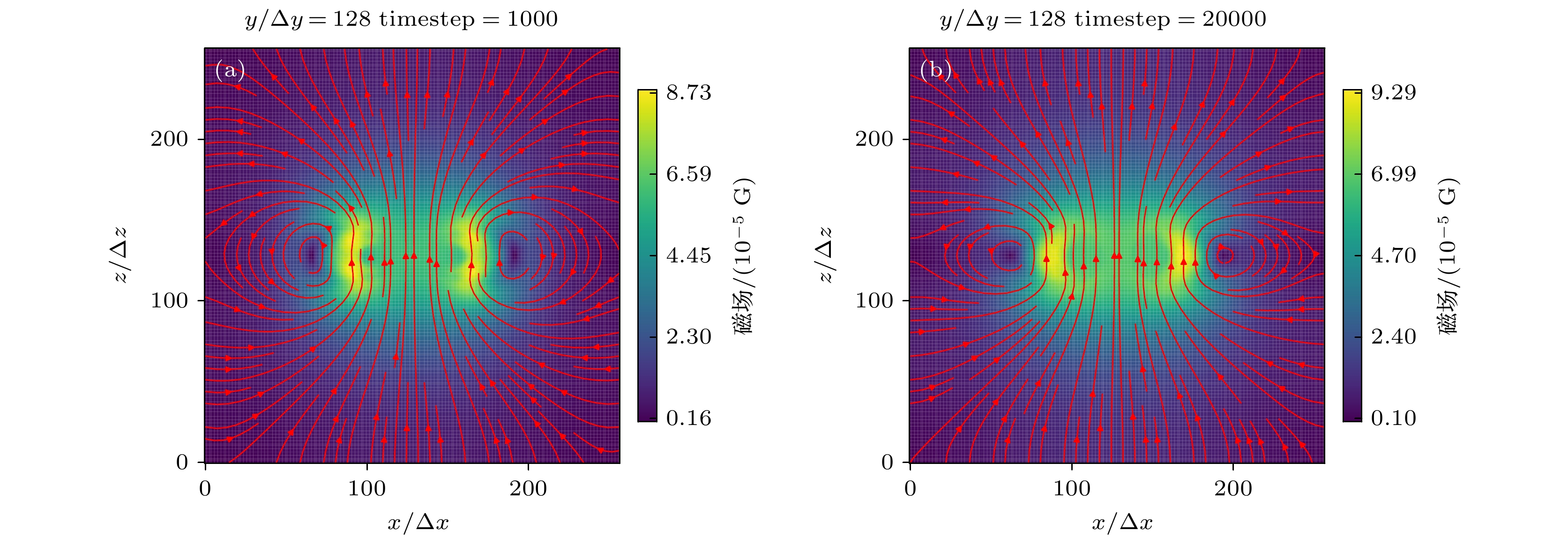
图 5 无电子束注入时网格x-z平面处扰动磁场的流线和分布 (a) t = 1000Δt; (b) t = 20000Δt
Fig. 5. Streamline and distribution of the disturbed magnetic field in the x-z plane of the grid when injected without electron beam: (a) t = 1000Δt; (b) t = 20000Δt.
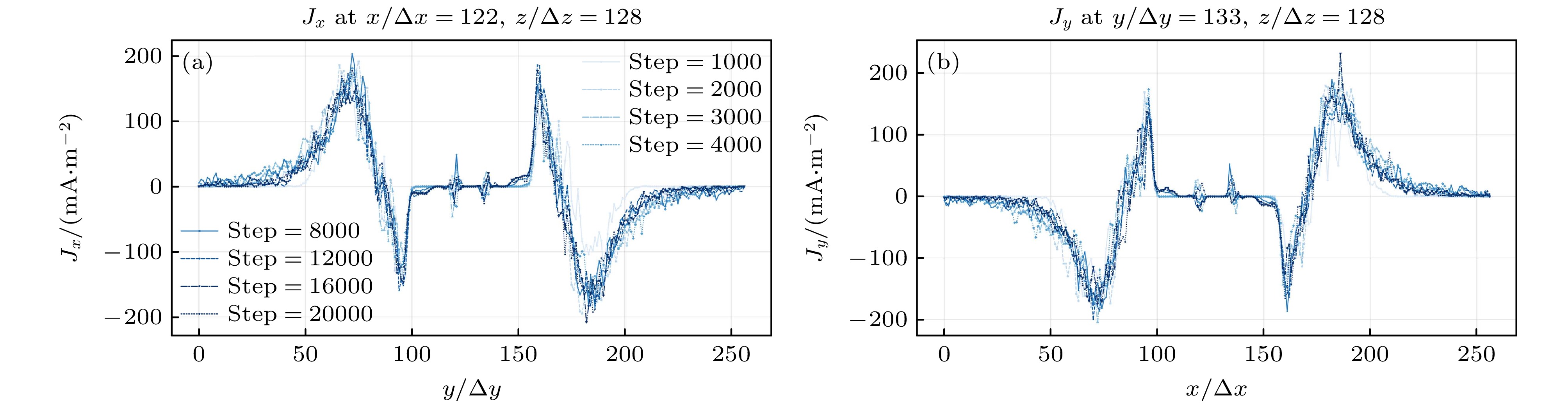
图 6 无电子束注入时不同时刻的电流密度分量剖面图 (a) Jx沿穿过赤道平面中心的y方向线; (b) Jy沿着穿过赤道平面中心的x方向线
Fig. 6. Profiles of the current density components at different time steps in the case without beam injection: (a) Jx along the y-direction line through the center of the equatorial plane; (b) Jy follows the line of x through the center of the equatorial plane.
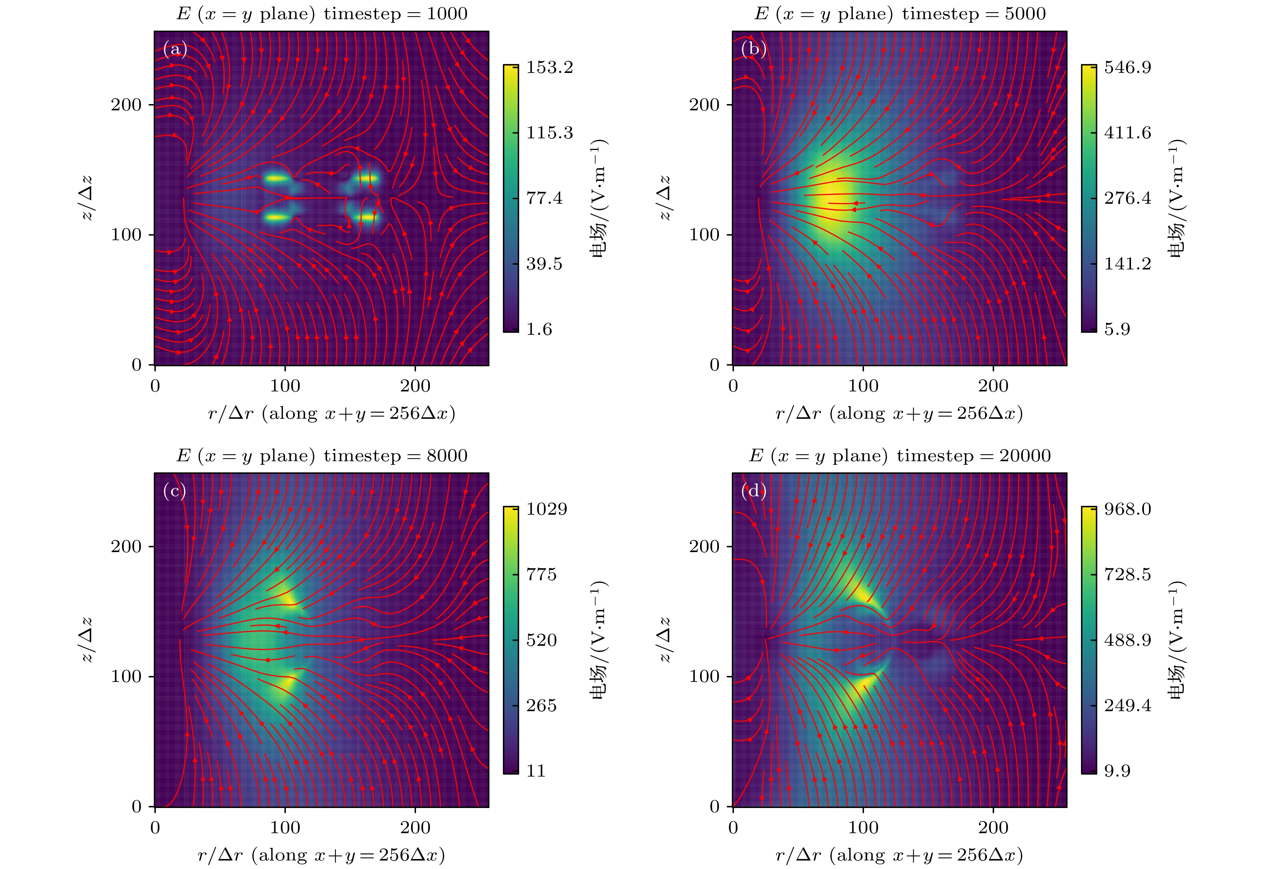
图 7 注入角度为0°的电子束作用下不同时间步长网格对角线平面($ x+y=256\Delta x $平面)电场的流线和分布 (a) t = 1000Δt; (b) t = 5000Δt; (c) t = 8000Δt; (d) t = 20000Δt
Fig. 7. Streamlines and distributions of the electric field on the grid diagonal plane ($ x+y=256\Delta x $ plane) with 0° injection angle at different time steps: (a) t = 1000Δt; (b) t = 5000Δt; (c) t = 8000Δt; (d) t = 20000Δt.
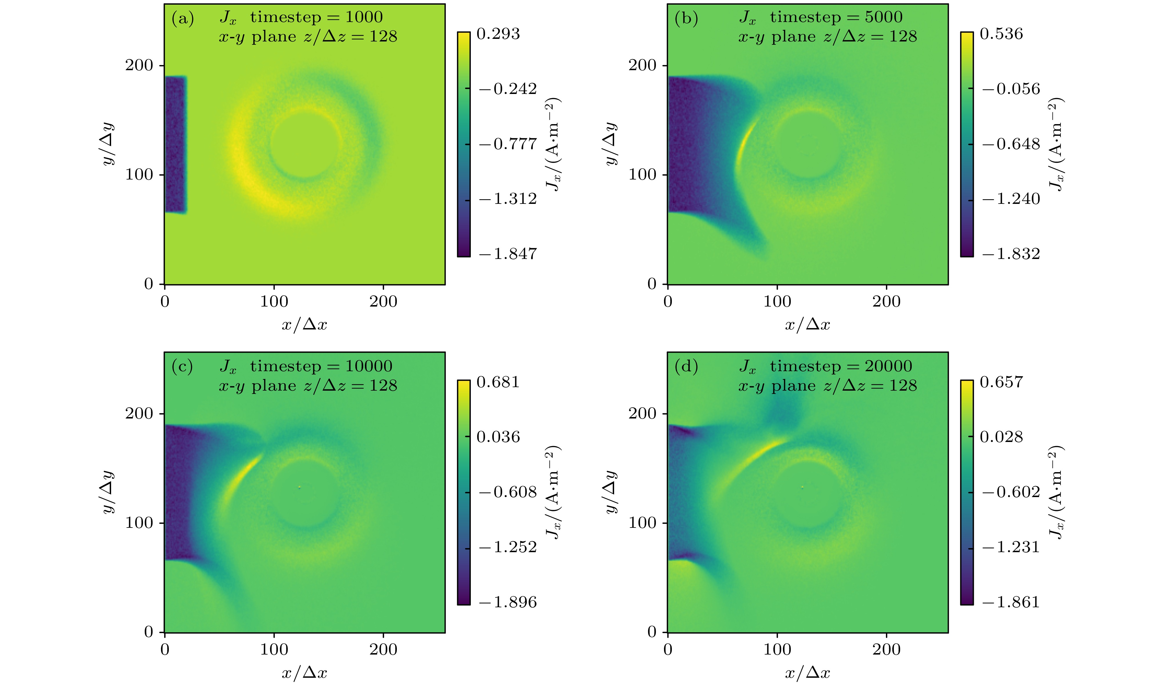
图 8 注入角度为0°的电子束作用下, 穿过网格中心的x-y平面上的Jx分布 (a) t = 1000Δt; (b) t = 5000Δt; (c) t = 10000Δt; (d) t = 20000Δt
Fig. 8. Jx distribution on the x-y plane through the center of the grid with 0° injection angle at different time steps: (a) t = 1000Δt; (b) t = 5000Δt; (c) t = 10000Δt; (d) t = 20000Δt.
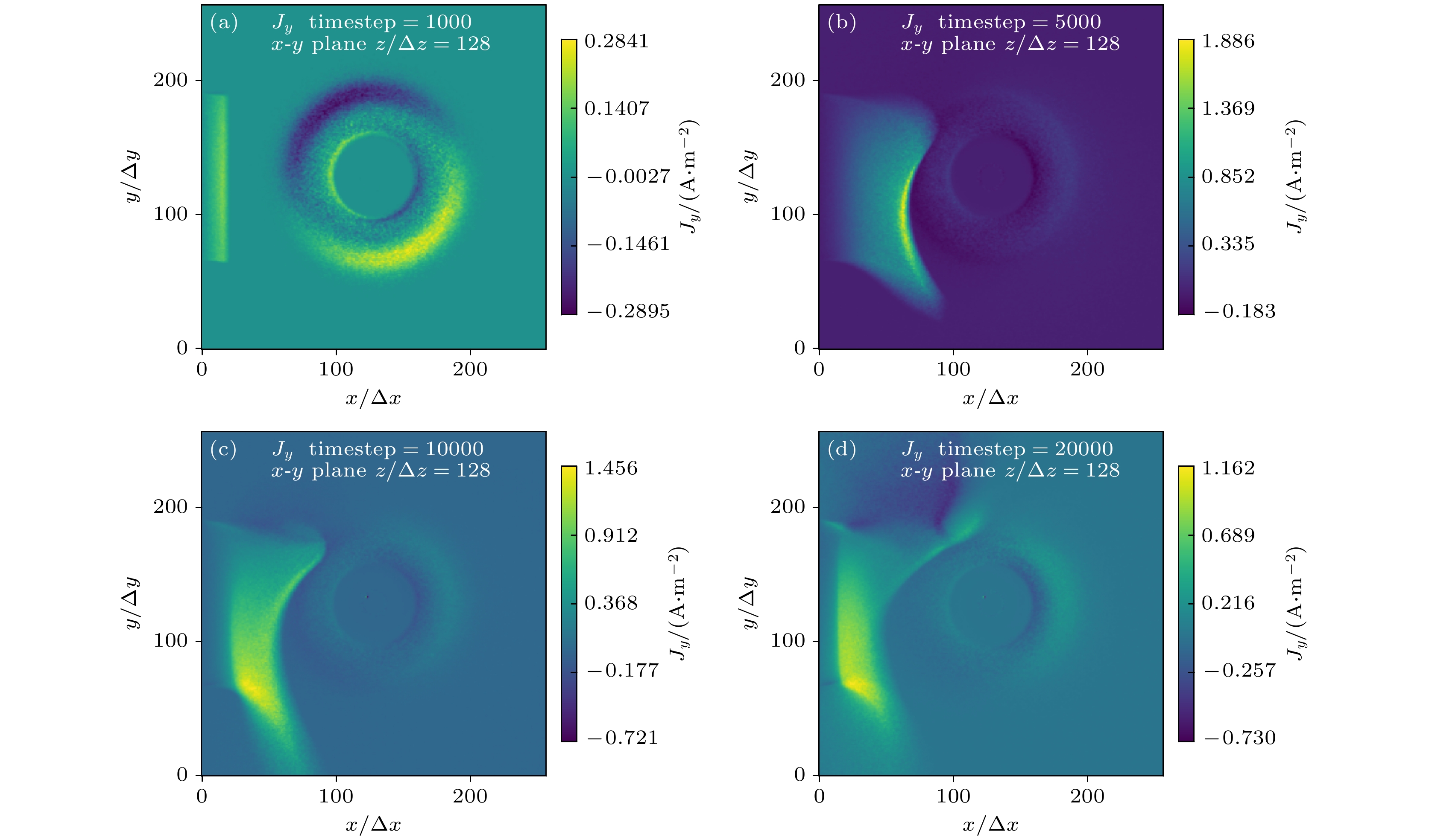
图 9 注入角度为0°的电子束作用下通过网格中心的x-y平面上的Jy分布 (a) t = 1000Δt; (b) t = 5000Δt; (c) t = 10000Δt; (d) t = 20000Δt
Fig. 9. Jy distribution on the x-y plane through the center of the grid with 0° injection angle at different time steps: (a) t = 1000Δt; (b) t = 5000Δt; (c) t = 10000Δt; (d) t = 20000Δt.
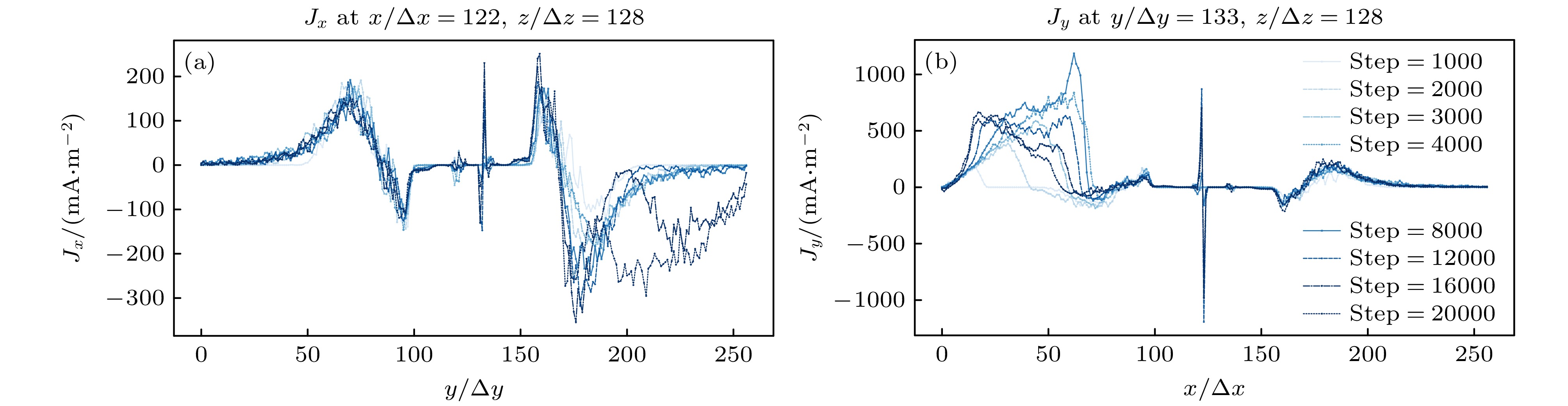
图 10 注入角度为0°的电子束作用下不同时刻的电流密度分量剖面图 (a) Jx沿穿过赤道平面中心的y方向线; (b) Jy沿着穿过赤道平面中心的x方向线
Fig. 10. Profiles of current density components at different time steps under beam injection with an injection angle of 0°: (a) Jx along the y-direction line through the center of the equatorial plane; (b) Jy along the x-direction line through the center of the equatorial plane
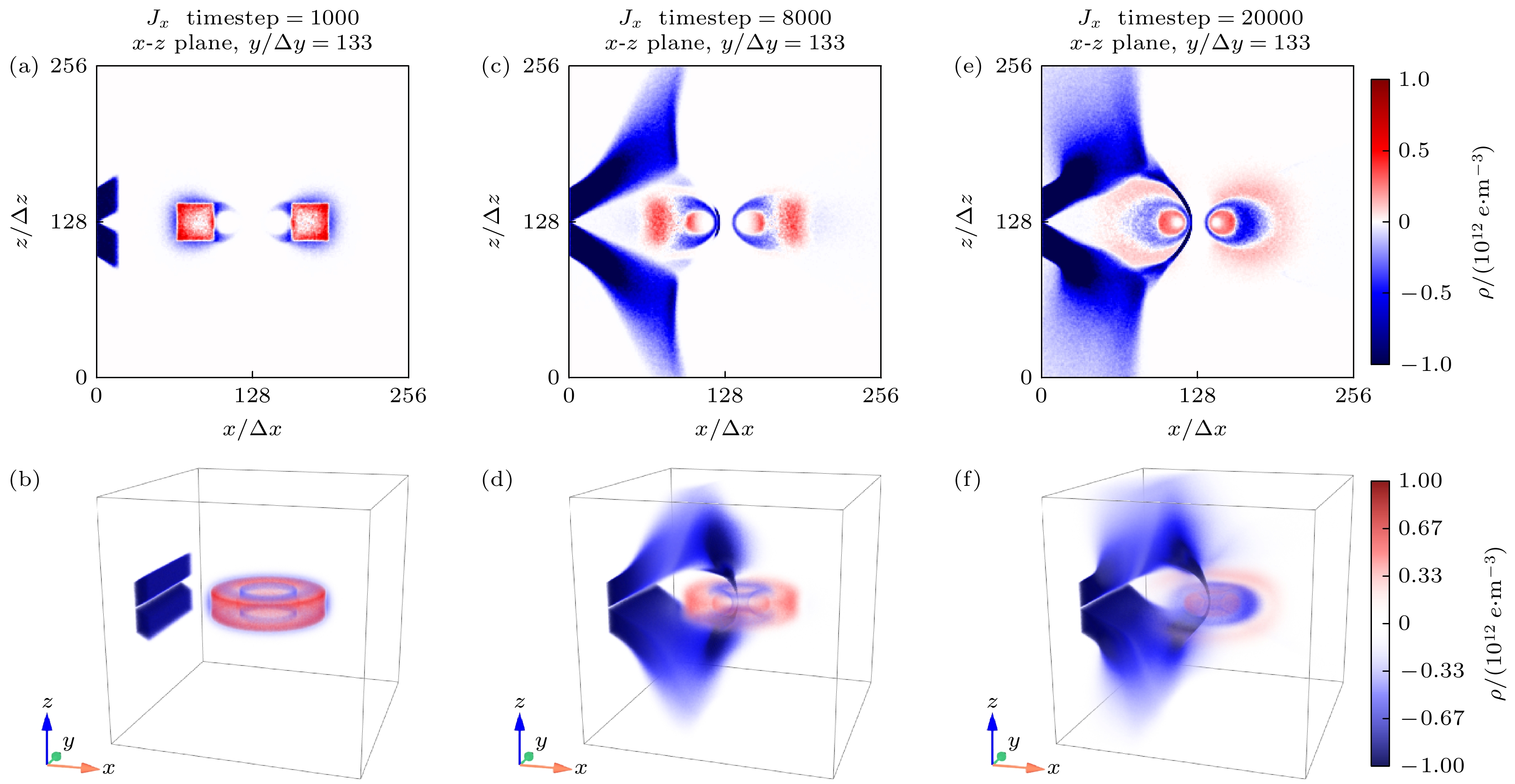
图 11 注入角度为30°的电子束作用下等离子体的电荷密度分布 (a), (c), (e)分别为t = 1000Δt, t = 8000Δt和t = 20000Δt时的二维空间分布; (b), (d), (f)分别为t = 1000Δt, t = 8000Δt和t = 20000Δt时的三维空间分布
Fig. 11. The charge number density distribution of plasma under electron beam injection with an injection angle of 30°: (a), (c), (e) The two-dimensional spatial distribution of t = 1000Δt; t = 8000Δt and t = 20000Δt; respectively; (b), (d), (f) the three-dimensional spatial distributions at t = 1000Δt, t = 8000Δt and t = 20000Δt, respectively.
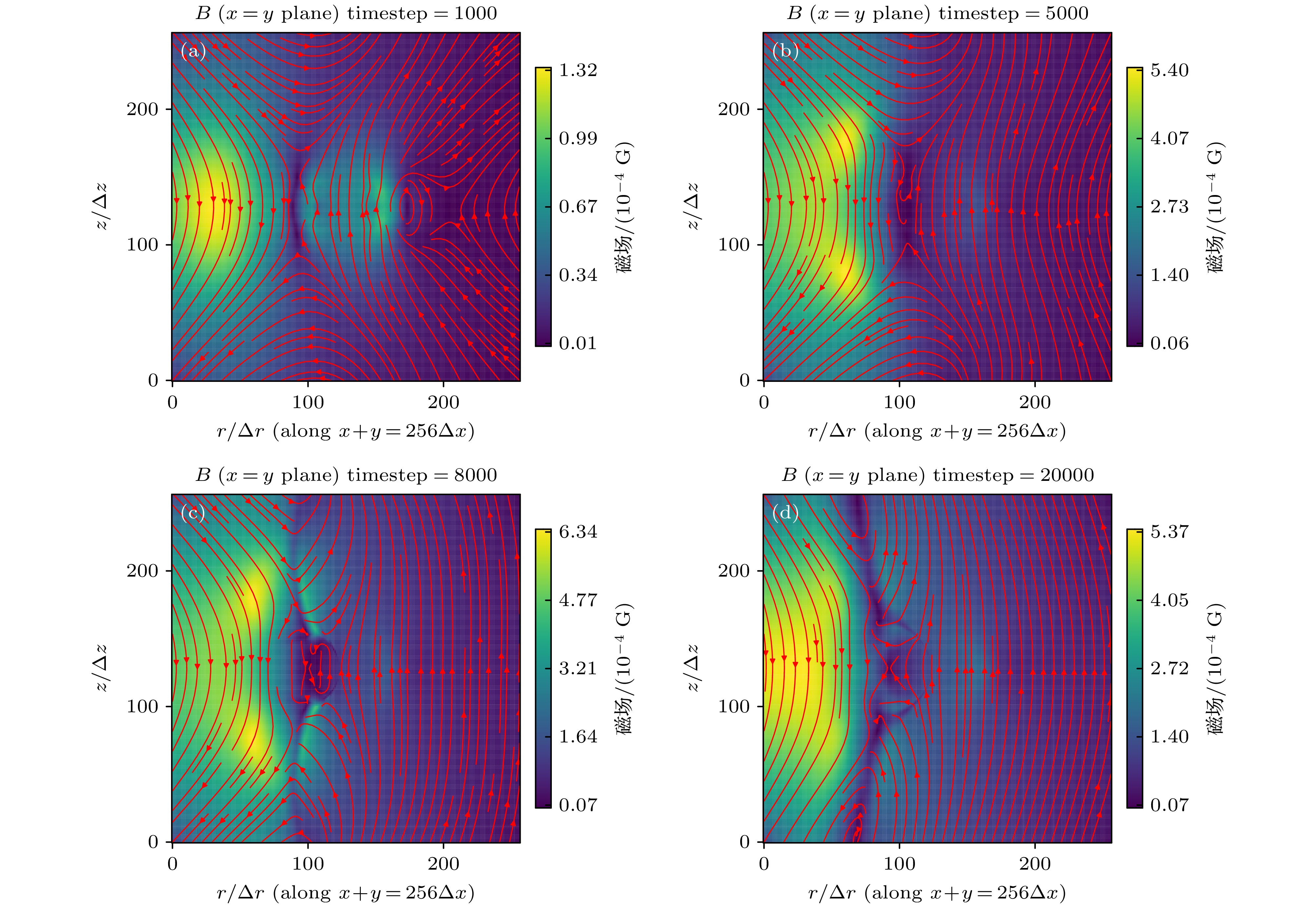
图 12 注入角度为30°的电子束作用下不同时刻网格对角线平面($ x+y=256\Delta x $平面)处扰动磁场的流线和分布 (a) t = 1000Δt; (b) t = 5000Δt; (c) t = 8000Δt; (d) t = 20000Δt
Fig. 12. Streamlines and distributions of the disturbed magnetic field on the diagonal plane ($ x+y=256\Delta x $ plane) with 30° injection angle at different time steps: (a) t = 1000Δt; (b) t = 5000Δt; (c) t = 8000Δt; (d) t = 20000Δt.
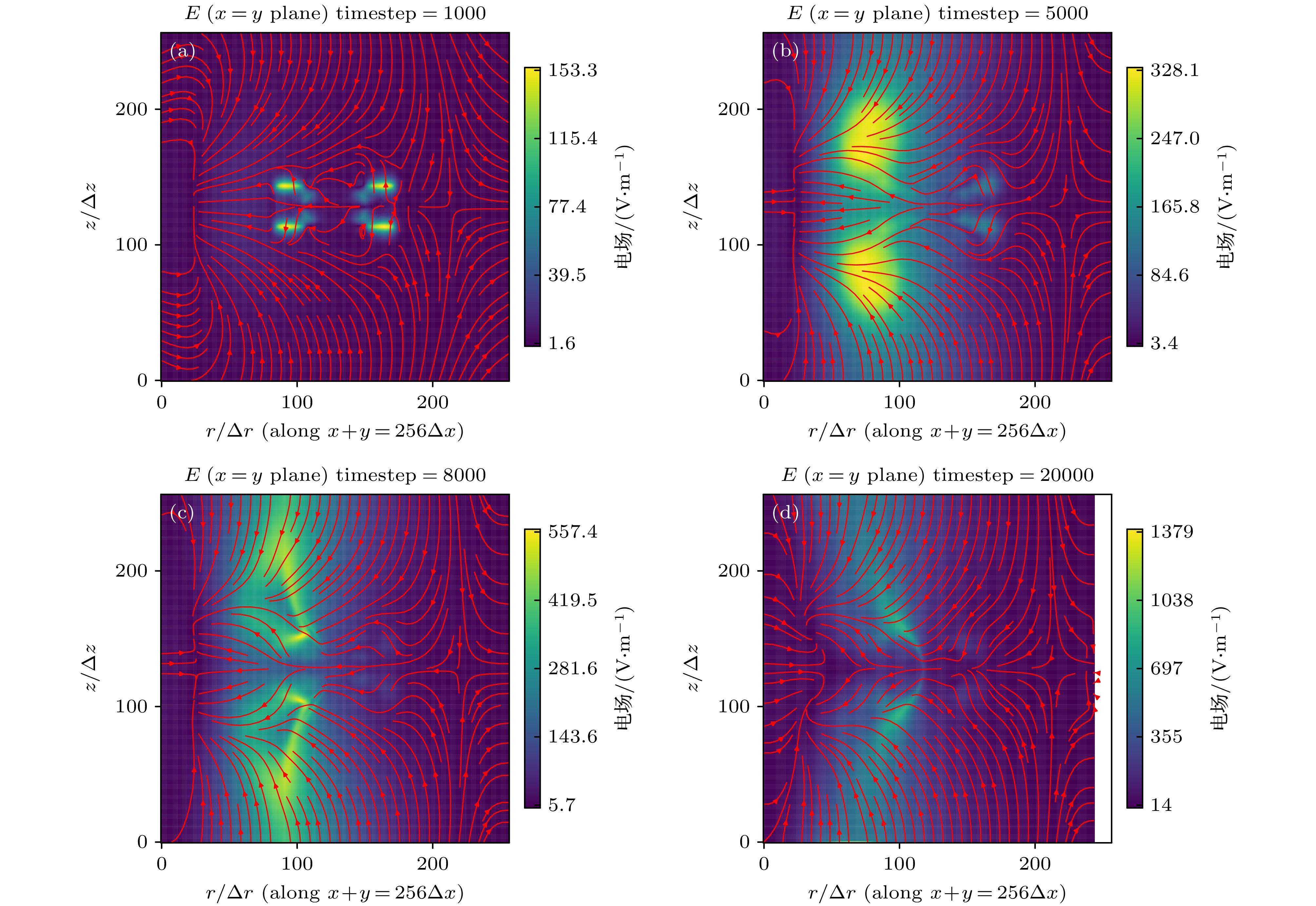
图 13 注入角度为30°的电子束作用下不同时刻网格对角线平面($ x+y=256\Delta x $平面)上的电场流线和分布 (a) t = 1000Δt; (b) t = 5000Δt; (c) t = 8000Δt; (d) t = 20000Δt
Fig. 13. Streamlines and distributions of the electric field on the diagonal plane ($ x+y=256\Delta x $ plane) with 30° injection angle at different time steps: (a) t = 1000Δt; (b) t = 5000Δt; (c) t = 8000Δt; (d) t = 20000Δt.
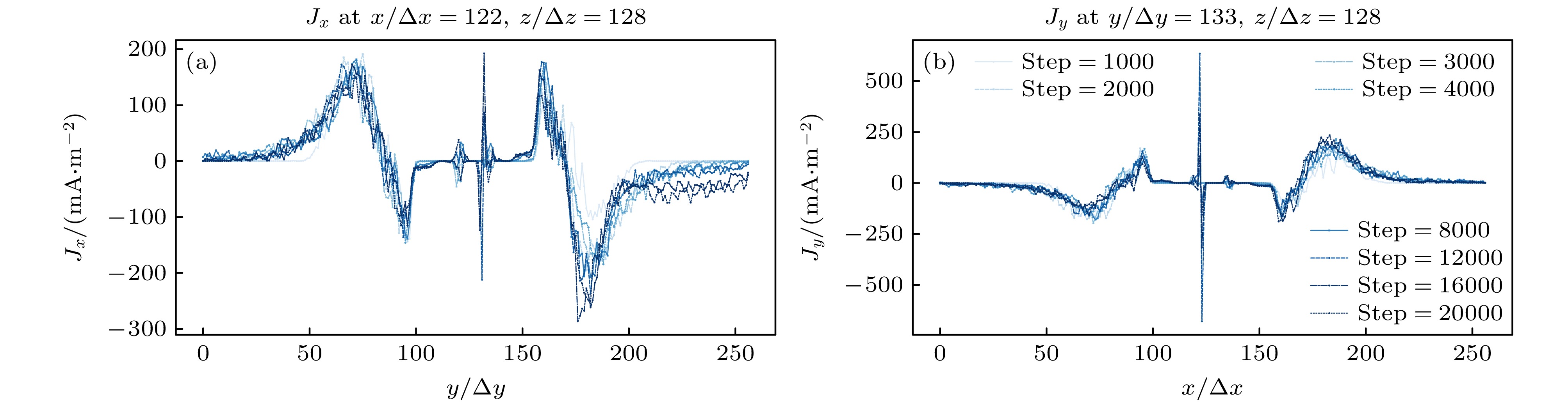
图 14 注入角度为30°的电子束作用下不同时刻电流密度分量剖面图 (a) Jx沿穿过赤道平面中心的y方向线; (b) Jy沿着穿过赤道平面中心的x方向线
Fig. 14. Profiles of current density components at different time steps under beam injection with an injection angle of 30°: (a) Jx along the y-direction line through the center of the equatorial plane; (b) Jy along the x-direction line through the center of the equatorial plane.
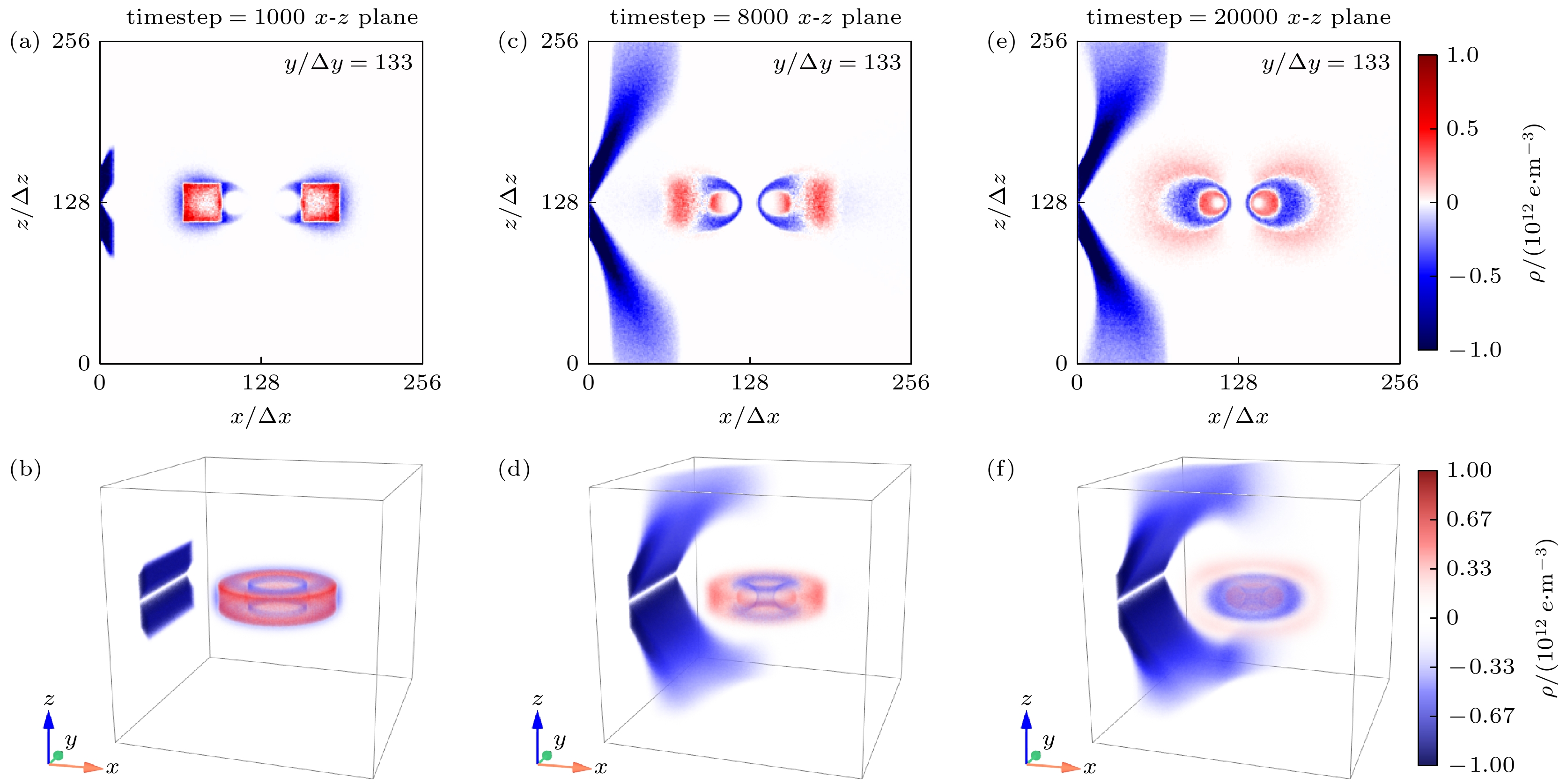
图 15 注入角度为60°的电子束作用下等离子体的电荷密度分布 (a), (c), (e)分别为t = 1000Δt, t = 8000Δt和t = 20000Δt时的二维空间分布; (b), (d), (f)分别为t = 1000Δt, t = 8000Δt和t = 20000Δt时的三维空间分布
Fig. 15. The charge number density distribution of plasma under electron beam injection with an injection angle of 60°: (a), (c), (e) The two-dimensional spatial distribution of t = 1000Δt, t = 8000Δt and t = 20000Δt, respectively; (b), (d), (f) the three-dimensional spatial distributions at t = 1000Δt, t = 8000Δt and t = 20000Δt, respectively.
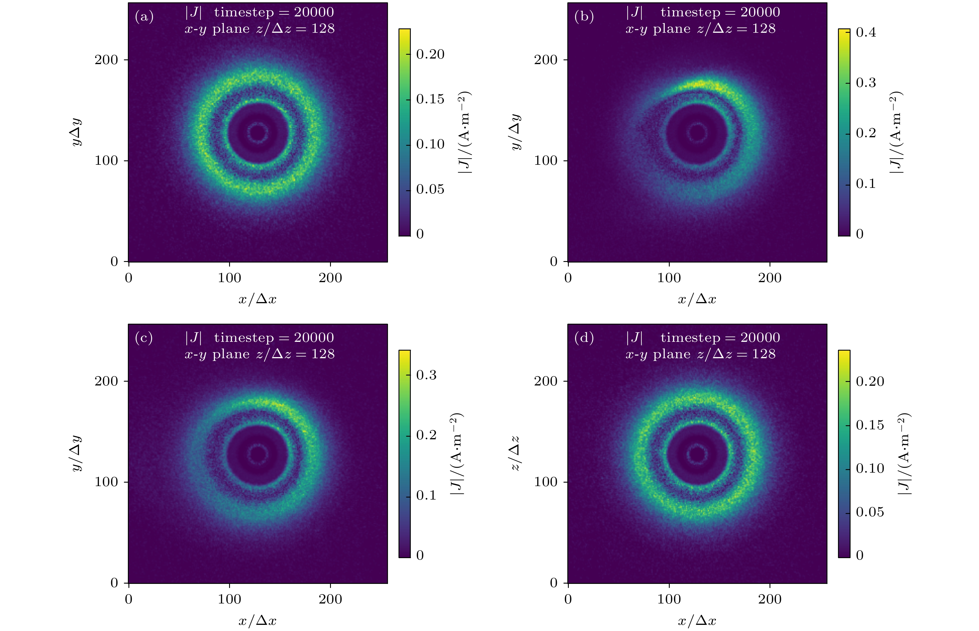
图 16 不同电子束注入情形下, 赤道面处主等离子体形成的环形电流分布 (a) 无电子束注入; (b) 以0°入射角入射; (c) 以30°入射角入射; (d) 以60°入射角入射
Fig. 16. The annular current distribution formed by the main plasma at the equatorial plane under different electron beam injection conditions: (a) Without electron beam injection; (b) incident at an angle of 0°; (c) incident at an angle of 30°; (d) incident at an angle of 60°.
-
[1] Levitt B, Maslovsky D, Mauel M E 2005 Phys. Rev. Lett. 94 175002
Google Scholar
[2] Baitha A R, Kumar A, Bhattacharjee S 2018 Rev. Sci. Instrum. 89 23503
Google Scholar
[3] Saitoh H, Yoshida Z, Morikawa J, Yano Y, Hayashi H, Mizushima T, Kawai Y, Kobayashi M, Mikami H 2010 Phys. Plasmas 17 112111
Google Scholar
[4] 王敬之, 马新, 项正, 顾旭东, 焦鹿怀, 雷良建, 倪彬彬 2022 71 229401
Google Scholar
Wang Z J, Ma X, Xiang Z, Gu X D, Jiao L H, Lei L J, Ni B B 2022 Acta Phys. Sin. 71 229401
Google Scholar
[5] 朱琪, 马新, 曹兴, 倪彬彬, 项正, 付松, 顾旭东, 张援农 2022 71 051101
Google Scholar
Zhu Q, Ma X, Cao X, Ni B B, Xiang Z, Fu S, Gu X D, Zhang Y N 2022 Acta Phys. Sin. 71 051101
Google Scholar
[6] 常珊珊, 倪彬彬, 赵正予, 汪枫, 李金星, 赵晶晶, 顾旭东, 周晨 2014 63 069401
Google Scholar
Chang S S, Ni B B, Zhao Z Y, Wang F, Li J X, Zhao J J, Gu X D, Zhou C 2014 Acta Phys. Sin. 63 069401
Google Scholar
[7] 倪彬彬, 赵正予, 顾旭东, 汪枫 2008 57 7937
Google Scholar
Ni B B, Zhao Z Y, Gu X D, Wang F 2008 Acta Phys. Sin. 57 7937
Google Scholar
[8] 顾旭东, 赵正予, 倪彬彬, 王翔, 邓峰 2008 57 6673
Google Scholar
Gu X D, Zhao Z Y, Ni B B, Wang X, Deng F 2008 Acta Phys. Sin. 57 6673
Google Scholar
[9] Korotova G I, Sibeck D G, Tahakashi K, Dai L, Spence H E, Kletzing C A, Wygant J R, Manweiler J W, Moya P S, Hwang K J, Redmon R J 2015 Ann. Geophys. 33 955
Google Scholar
[10] Zong Q G, Hao Y Q, Wang Y F 2009 Sci. China Ser. E-Technol. Sci. 52 3698
Google Scholar
[11] Zong Q G, Wang Y F, Yang B, Fu S Y, Pu Z Y, Xie L, Fritz T A 2008 Sci. China Ser. E-Technol. Sci. 51 1620
Google Scholar
[12] Van Compernolle B, An X, Bortnik J, Thorne R M, Pribyl P, Gekelman W 2015 Phys. Rev. Lett. 114 245002
Google Scholar
[13] Chen J, Powis A T, Kaganovich I D, Wang Z B, Yu Y 2025 Phys. Rev. Lett. 135 45301
Google Scholar
[14] Nishio K, Mori K, Alpert H S 2025 AIAA Scitech Forum AIAA 2025
[15] Huang H, Wang Z B, Wang X G, Tao X 2018 Chin. Phys. B 27 015201
Google Scholar
[16] Huang H, Wang Z B, Wang X G, Tao X. 2019 Phys. Plasmas 26 022106
Google Scholar
[17] Xiao Q M, Wang Z B, Wang X G, Xiao C J, Yang X Y, Zheng J X 2017 Plasma Sci. Technol. 19 35301
Google Scholar
[18] 刘腾, 张国书, 杜俊杰, 杨庆喜, 黄淑龙, 刘云辉 2022 核聚变与等离子体物理 42 271
Liu T, Zhang G S, Du J J, Yang Q X, Huang S L, Liu Y H 2022 Nucl. Fusion Plasma Phys. 42 271
[19] 孙玄, 刘明, 谢锦林, 余羿, 林木楠, 张情 2014 中国科学技术大学学报 44 374
Sun X, Liu M, Xie J L, Yu Y, Lin M N, Zhang Q 2014 J. Univ. Sci. Technol. China 44 374
[20] Xiao C J, Chen Y H, Yang X Y, Xu T C, Wang L, Xu M, Guo D, Yu Y, Lin C 2016 Rev. Sci. Instrum. 87 11D610
Google Scholar
[21] Sun C J, Sang C F, Ye H, Wang Q, Liu H, Wang Z H, Wang H J, Ke R, Wang Y, Zhang Y J, Wang D Z 2021 Fusion Eng. Des. 162 112074
Google Scholar
[22] 王志斌, 沈炀, 余羿, 陈坚 2024 南方能源建设 11 1
Wang Z B, Shen Y, Yu Y, Chen J 2024 Southern Energy Construction 11 1
[23] Zhukovsky A, Michael P C, Schultz J H, Smith B A, Minervini J V, Kesner J, Radovinsky A, Garnier D, Mauel M 2005 Fusion Eng. Des. 75–79 29
[24] Saitoh H, Yoshida Z, Morikawa J, Furukawa M, Yano Y, Kawai Y, Kobayashi M, Vogel G, Mikami H 2011 Phys. Plasmas 18 056102
Google Scholar
[25] Barnes C W, Jarboe T R, Henins I, Sherwood A R, Knox S O, Gribble R, Hoida H W, Klingner P L, Lilliequist C G, Linford R K, Platts D A, Spencer R L, Tuszewski M 1984 Nucl. Fusion 24 267
Google Scholar
[26] Yoshida Z, Ogawa Y, Morikawa J, Watanabe S, Yano Y, Mizumaki S, Tosaka T, Ohtani Y, Hayakawa A, Shibui M 2006 Plasma Fusion Res. 1 8
Google Scholar
[27] von der Linden J, Nissl S, Deller A, Singer M, Belmore N, Hugenschmidt C P, Pedersen T S, Saitoh H, Stenson E V 2024 Eur. Phys. J. D 78 146
Google Scholar
[28] Deller A, von der Linden J, Ni Ss L S, Michishio K, Oshima N, Higaki H, Stenson E V 2024 Phys. Rev. E 110 L23201
[29] Derouillat J, Beck A, Pérez F, Vinci T, Chiaramello M, Grassi A, Flé M, Bouchard G, Plotnikov I, Aunai N, Dargent J, Riconda C, Grech M 2018 Comput. Phys. Commun. 222 351
Google Scholar
[30] Sun J, Gao X, Chen L, Lu Q, Tao X, Wang S 2016 Phys. Plasmas 23 22901
Google Scholar
[31] Ortner M, Bandeira L G C 2020 SoftwareX 11 100466
Google Scholar


 下载:
下载:


计量
- 文章访问数: 646
- PDF下载量: 28
- 被引次数: 0
