


-
针对现有毫米波频率可重构天线频率调谐比小的问题, 本文设计了一款宽频带双频毫米波频率可重构滤波天线. 天线以PIN二极管为重构开关, 选择阶梯阻抗谐振器作为可重构带通滤波器, 并加载U型枝节引入陷波; 通过微带线-带状线过渡馈电结构将滤波器与Vivaldi天线级联, 并设计了金属腔隔离辐射和滤波两部分, 有效降低了电磁干扰和交叉极化. 测试结果显示: PIN二极管处于导通状态时, 天线工作在25.9—28.6 GHz, 最大增益为8.83 dBi; PIN二极管处于断开状态时, 天线工作在32.6—35.9 GHz, 最大增益为9.97 dBi; 可重构中心频率比达到了1∶1.26, 两个频带的交叉极化电平均低于–20 dB.To solve the problem of small frequency turning ratio of the frequency-reconfigurable antenna operating in the millimeter-wave band, a millimeter-wave dual-band frequency-reconfigurable filtering antenna is proposed in this work. The proposed filtering antenna consists of a reconfigurable bandpass filter and an ultra-wideband double layer Vivaldi antenna. The reconfigurable bandpass filter is comprised of several components, including parallel coupled lines, stepped impedance resonator (SIR), PIN diodes, U-shaped branches, and bias network. The reconfigurable filter is integrated in the feedline of the Vivaldi antenna, which provides a simple structure and possesses flexibility for further expansion. The reconfigurable characteristic is realized by controlling the electrical length of the open circuit stepped impedance resonator through two PIN diodes, which not only acts as a switch but also affects the impedance matching within the millimeter wave band. Firstly, the equivalent circuit model of the SIR loaded with PIN diode and bias network is analyzed and simulated to achieve dual-band reconfigurability in the Ka-band. The bias network consists of fan-shaped branches and high-impedance microstrip lines, which suppresses the flow of RF signals. Two notches are introduced by the two U-shaped branches, which are arranged beside the parallel coupling line without affecting the performance of the reconfigurable filter. The realized two notches are located in the non-operating frequency band between the two reconfigurable bands, which enhances the out-of band performances of the reconfigurable filter. Then, to suppress the unnecessary coupling effect and concentrate the energy on the feedline of the Vivaldi antenna, some metallized vias are loaded on the two sides of the feedline. Finally, a metal cavity is introduced to isolate the radiation from filtering components, and some metal columns are loaded inside the cavity for improving the self-resonance of the metal cavity, which effectively improves the cross-polarization level of the filtering antenna. The measured results show that the proposed antenna operates in a range from 25.9 to 28.6 GHz with a maximum gain of 8.83 dBi when the PIN diodes are in the on state, and in a range from 32.6 to 35.9 GHz with a maximum gain of 9.97 dBi when the PIN diodes are in the off state. The center frequency ratio between two reconfigurable frequency bands reaches 1∶1.26, and the cross-polarization levels are all less than –20 dB in both operating bands.
-
Keywords:
- millimeter-wave antenna /
- filtering antenna /
- frequency reconfigurable /
- PIN diode
[1] Yang X J, Ge L, Ji Y, Zeng X R, Luk K M 2019 IEEE Trans. Antennas Propag. 67 6639
 Google Scholar
[2] 袁子东, 高军, 曹祥玉, 杨欢欢, 杨群, 李文强, 商楷 2014 63 014102
Google Scholar
Yuan Z D, Gao J, Cao X Y, Yang H H, Yang Q, Li W Q, Shang K 2014 Acta Phys. Sin. 63 014102
Google Scholar
[3] Feng L Y, Leung K W 2016 IEEE Trans. Antennas Propag. 64 340
Google Scholar
[4] Xiang B J, Zheng S Y, Wong H, Pan Y M, Wang K X, Xia M H 2018 IEEE Trans. Antennas Propag. 66 657
Google Scholar
[5] Deng Q J, Pan Y M, Liu X Y, Leung K W 2023 IEEE Trans. Antennas Propag. 71 1971
Google Scholar
[6] Zou J J, Zhao Y, Yang X J, Ge L, Sun Y X 2023 IEEE Antennas Wirel. Propag. Lett. 22 1513
Google Scholar
[7] Chen Q G, Ala-Laurinaho J, Khripkov A, Ilvonen J, Moreno R M, Viikari V 2023 IEEE Trans. Antennas Propag. 71 6628
Google Scholar
[8] Patriotis M, Ayoub F N, Tawk Y, Costantine J, Christodoulou C G 2021 IEEE Antennas Wirel. Propag. Lett. 20 2095
Google Scholar
[9] Kumar Naik K, Sailaja B V S 2024 IEEE Open J. Antennas Propag. 5 673
Google Scholar
[10] Yang W C, Zhou C Y, Xue Q, Wen Q Y, Che W Q 2021 IEEE Trans. Antennas Propag. 69 4359
Google Scholar
[11] 李靖豪, 杨琬琛, 周晨昱, 薛泉, 文岐业, 车文荃 2022 无线电工程 52 317
Google Scholar
Li J H, Yang W C, Zhou C Y, Xue Q, Wen Q Y, Che W Q 2022 Radio Engineering 52 317
Google Scholar
[12] Kim J, Oh J 2020 IEEE Antennas Wirel. Propag. Lett. 19 1958
Google Scholar
[13] Jilani S F, Rahimian A, Alfadhl Y, Alomainy A 2018 Flexible and Printed Electronics 3 1
Google Scholar
[14] Karthika K, Kavitha K, Darsani S, Preethi B, Pavithra P S 2022 8th International Conference on Advanced Computing and Communication Systems (ICACCS) Coimbatore, India, March 25–26, 2022pp907
Google Scholar
[15] Choi J, Park J, Youn Y, Hwang W, Seong H, Whang Y N, Hong W 2020 Trans. Microw. Theory Tech. 68 1872
Google Scholar
[16] Sun W, Liu S X, Zhu X, Zhang X L, Chi P L, Yang T 2022 IEEE Trans. Antennas Propag. 70 156
Google Scholar
[17] Shi Y R, Ni X Y, Qian Z Y, He S J, Feng W J 2023 IEEE Antennas Wirel. Propag. Lett. 22 3097
Google Scholar
[18] Liu Q D, Dong Q, Wen J X, Ye L H, Wu D L, Zhang X Y 2023 IEEE Antennas Wirel. Propag. Lett. 22 2310
Google Scholar
[19] Kuosmanen M, Holopainen J, Ala-Laurinaho J, Kiuru T, Viikari V 2023 IEEE Trans. Antennas Propag. 71 6546
Google Scholar
[20] Guo C G, Zhang Z, Fu X N, Wang J H 2023 IEEE Antennas Wirel. Propag. Lett. 22 1793
Google Scholar
[21] Ma T C, Dang Q H, Fumeaux C, Nguyen-Trong N 2024 IEEE Trans. Antennas Propag. 72 2998
Google Scholar
[22] Tewari N, Dadel M, Srivastava S 2023 IEEE Microwaves, Antennas, and Propagation Conference (MAPCON). Ahmedabad, India, December 11–14, 2023 p1
Google Scholar
[23] Patriotis M, Ayoub F N, Tawk Y, Costantine J, Christodoulou C G 2021 IEEE Open J. Antennas Propag. 2 759
Google Scholar
[24] 邹晓鋆, 许旭光, 康国钦, 朱航, 谭铭, 宋伟 2023 电子与信息学报 45 3973
Google Scholar
Zou X J, Xu X G, Kang G Q, Zhu H, Tan M, Song W 2023 J Electron. Inf. Techn. 45 3973
Google Scholar
[25] Mandal M K, Sanyal S 2006 IEEE Microw. Wirel. Compon. Lett. 16 597
Google Scholar
[26] Lu J C, Liao C K, Chang C Y 2008 Trans. Microw. Theory Tech. 56 2101
Google Scholar
[27] Tu W H 2010 IEEE Microw. Wirel. Compon. Lett. 20 208
Google Scholar
[28] 冯丽君 2022 硕士学位论文 (四川: 电子科技大学)
Feng L J 2022 M. S. Thesis (Chengdu: University of Electronic Science and Technology of China
[29] March S L 1985 Trans. Microw. Theory Tech. 3 269
Google Scholar
[30] Xu J, Wu W, Kang W, Miao C 2012 IEEE Microw. Wirel. Compon. Lett. 22 351
Google Scholar
[31] Wan F Y, Wu L L, Ravelo B, Ge J X 2020 IEEE Trans. Electromagn Compat. 62 1813
Google Scholar
[32] Jiang W, Che W Q 2012 IEEE Antennas Wirel. Propag. Lett. 11 293
Google Scholar
-
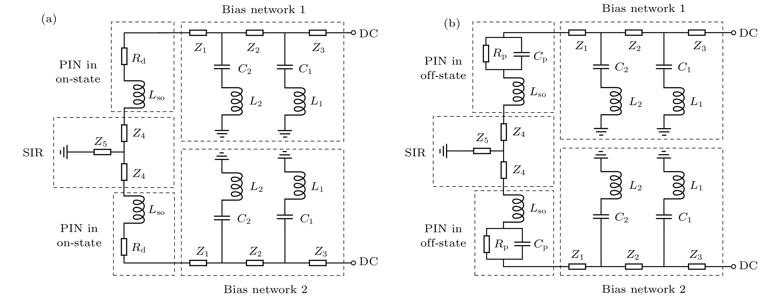
图 2 SIR结构加载直流偏置网络的等效电路模型 (a) PIN二极管导通; (b) PIN二极管断开
Fig. 2. Equivalent circuit model of SIR structure loaded DC bias networks: (a) PIN diodes are on state; (b) PIN diodes are off state.
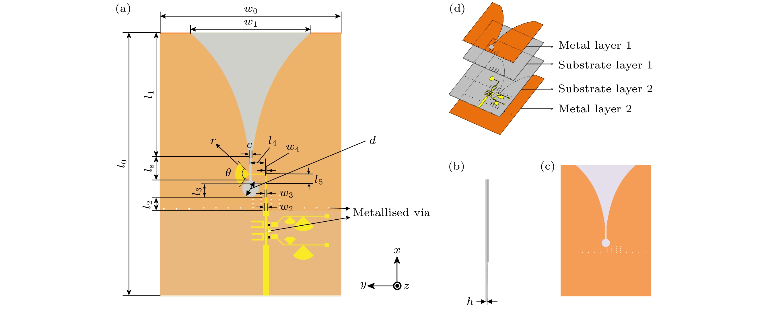
图 4 毫米波频率可重构天线三维视图 (a)顶面; (b)侧面; (c)底面; (d)三维爆炸图
Fig. 4. Millimetre wave frequency reconfigurable antenna three dimensional (3D) view: (a) Top view; (b) side view; (c) bottom view; (d) 3D exploded view
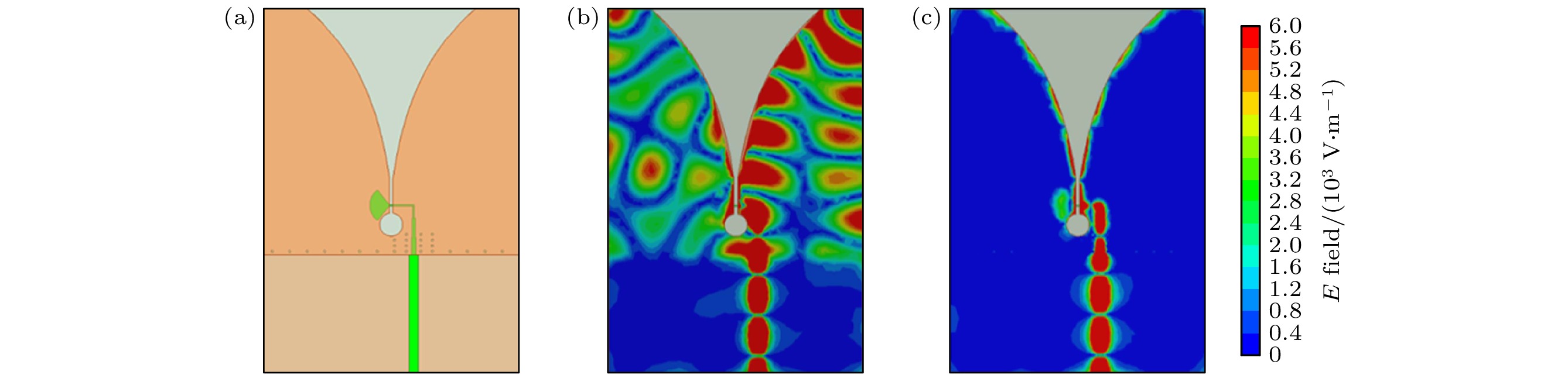
图 5 Vivaldi双面天线及其加载金属化过孔前后电场分布 (a)天线结构; (b)未加载金属化过孔; (c)加载金属化过孔
Fig. 5. Double-layer Vivaldi antenna and its electric field distribution before and after loaded the metallised via: (a) Antenna structure; (b) unloaded metallised via; (c) loaded metallised via.
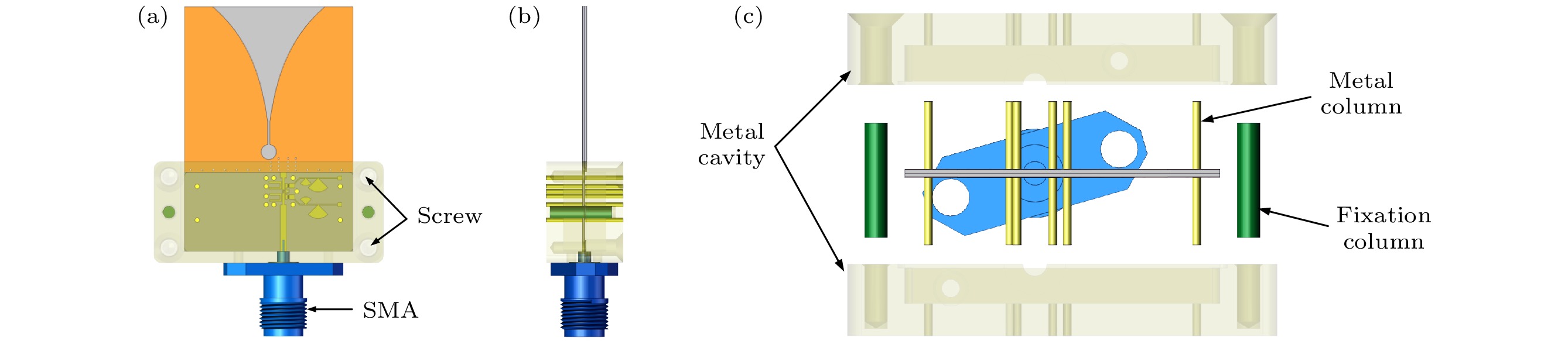
图 6 加载金属腔后天线的三维视图 (a)顶面; (b)侧面; (c)三维爆炸图
Fig. 6. 3D view of antenna loaded metal cavity: (a) Top view; (b) side view; (c) 3D exploded view.
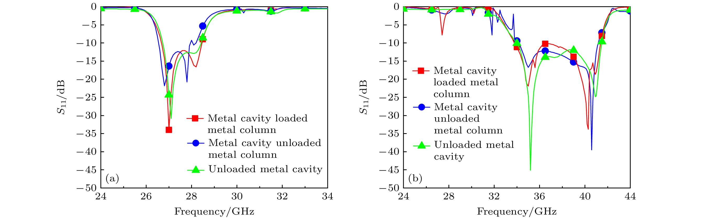
图 7 加载金属腔和金属柱对天线反射系数的影响 (a) PIN二极管导通; (b) PIN二极管断开
Fig. 7. Effect of loaded metal cavity and metal column on antenna reflection coefficient: (a) PIN diodes are on state; (b) PIN diodes are off state.
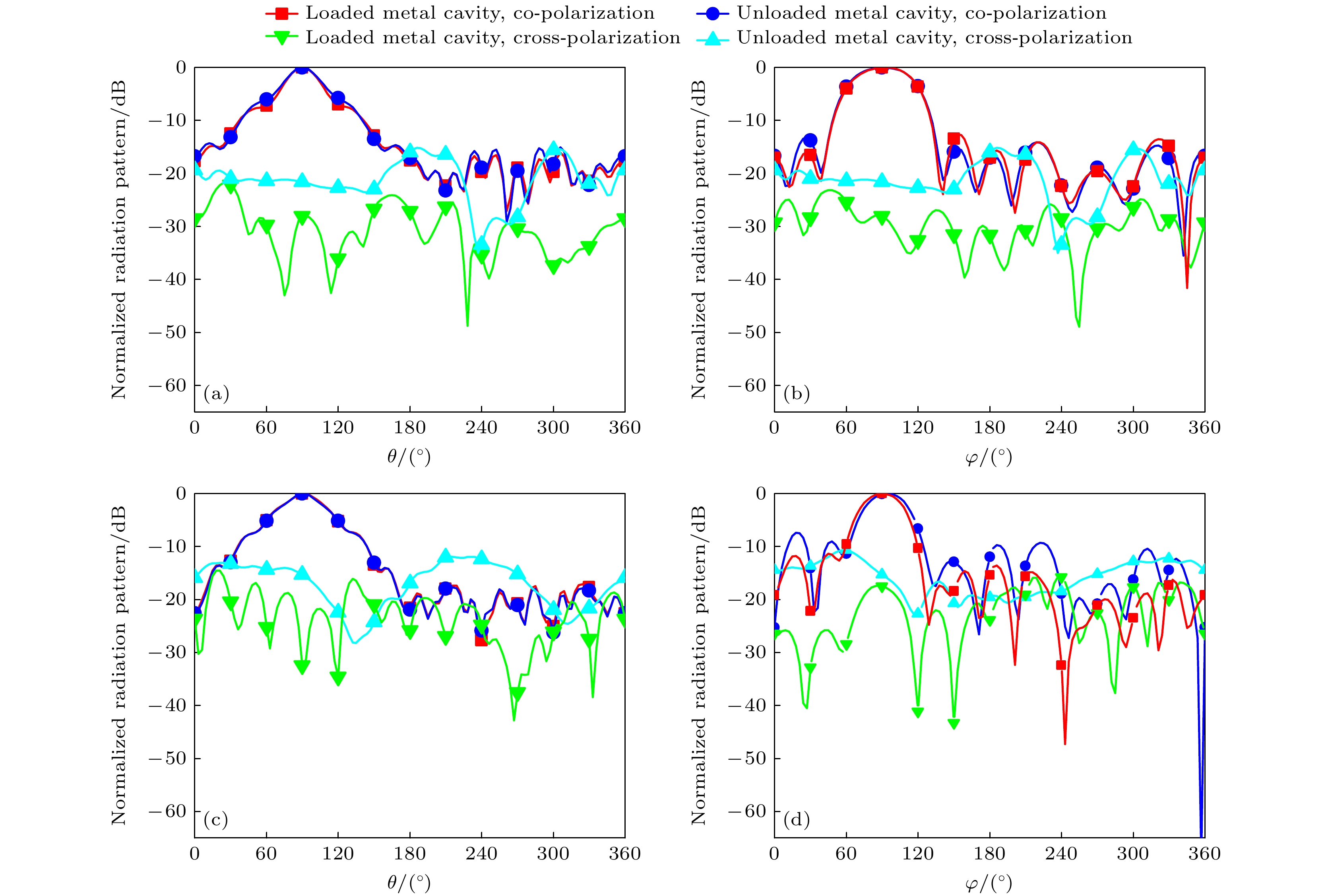
图 8 加载金属腔对天线辐射方向图的影响. PIN二极管导通, 27 GHz时(a) E面辐射方向图, (b) H面辐射方向图; PIN二极管断开, 35 GHz时(c) E面方向图, (d) H面方向图
Fig. 8. Effect of loaded metal cavity on antenna radiation pattern: (a) PIN diodes are on state, E-plane pattern at 27 GHz; (b) PIN diodes are on state, H-plane pattern at 27 GHz; (c) PIN diodes are off state, E-plane pattern at 35 GHz; (d) PIN diodes are off state, H-plane pattern at 35 GHz.
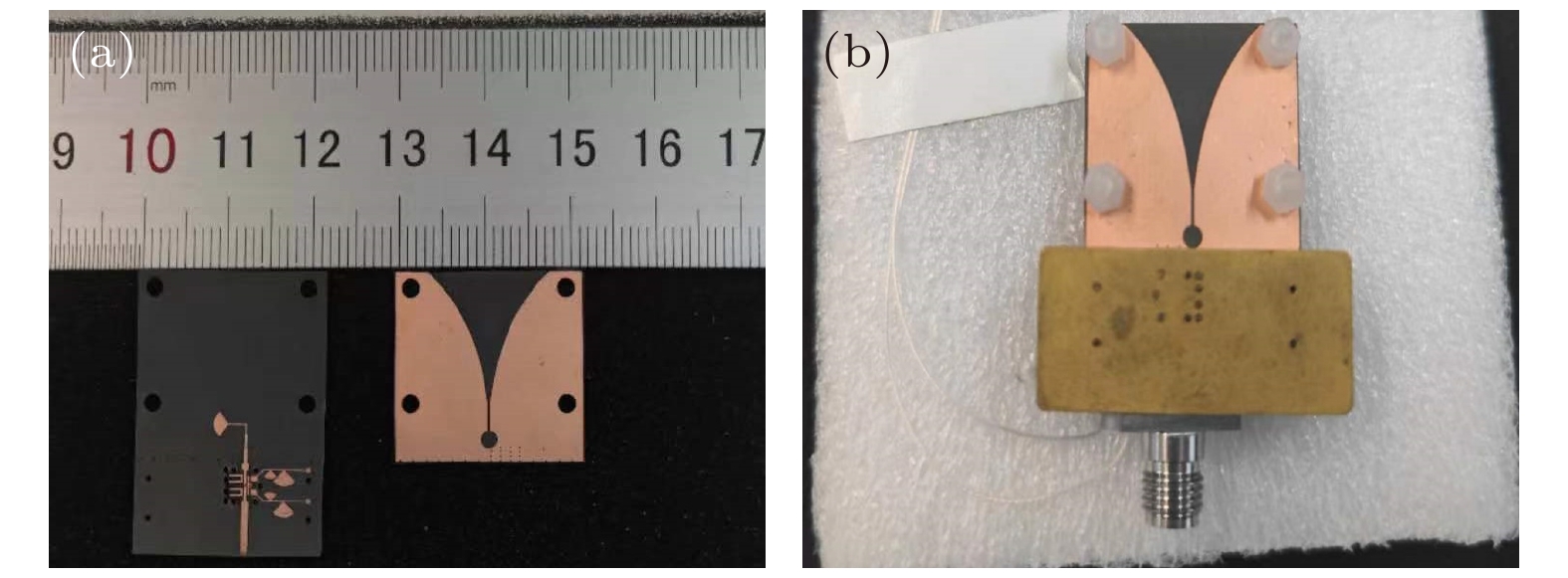
图 9 制作的天线实物图 (a) Vivaldi天线和可重构滤波器; (b)加载金属腔的天线
Fig. 9. Photographs of the fabricated antenna: (a) Vivaldi antenna and the reconfigurable filter; (b) the antenna loaded metal cavity.
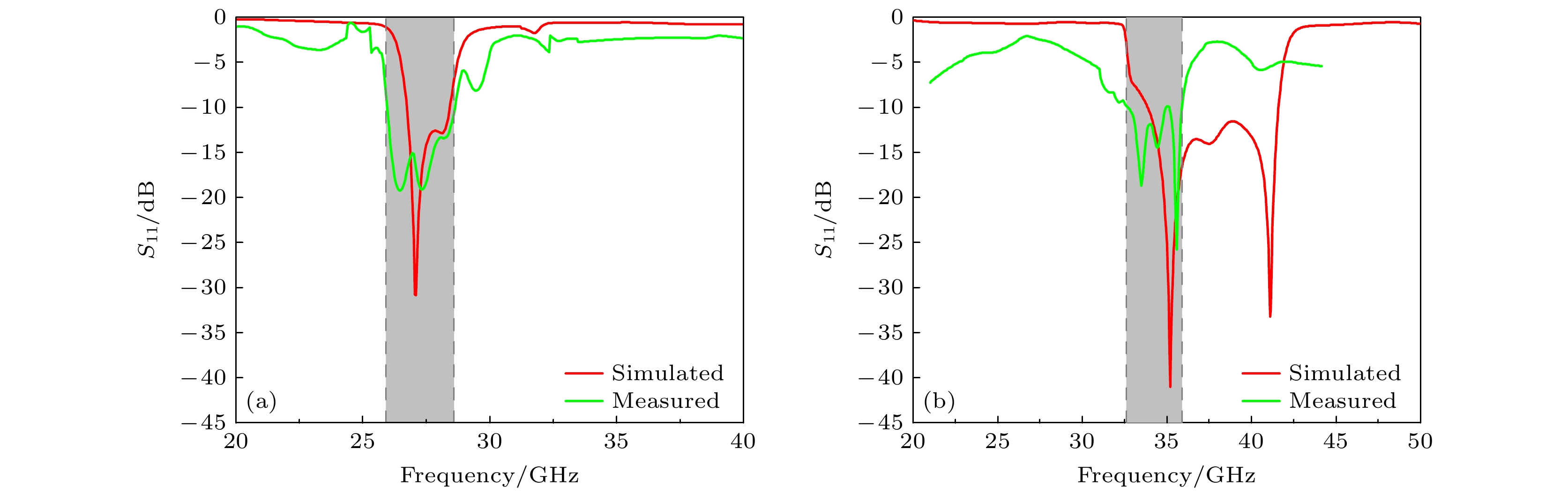
图 10 频率可重构天线仿真与实测反射系数$ S_{11} $曲线 (a) PIN二极管导通; (b) PIN二极管断开
Fig. 10. Frequency reconfigurable antenna simulated and measured reflection coefficient $ S_{11} $ curves: (a) PIN diodes are on state; (b) PIN diodes are off state.
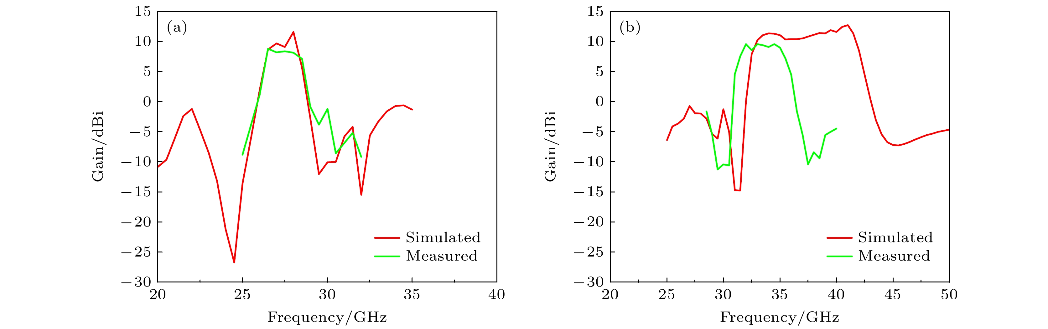
图 11 频率可重构天线仿真与实测增益曲线 (a) PIN二极管导通; (b) PIN二极管断开
Fig. 11. Frequency reconfigurable antenna simulated and measured Gain curves: (a) PIN diodes are on state; (b) PIN diodes are off state.
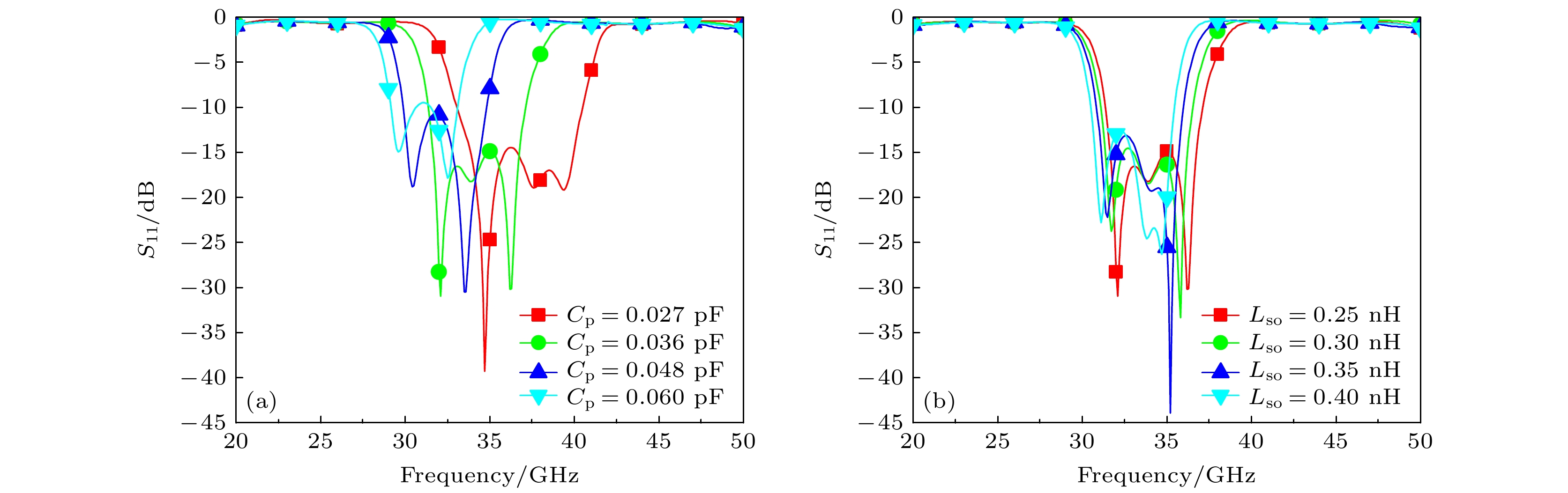
图 12 PIN二极管的寄生参数对天线反射系数$ S_{11} $的影响 (a)$ C_{\rm {p}} $的频率响应; (b)$ L_{\rm {so}} $的频率响应
Fig. 12. Effect of parasitic parameters of the PIN diode on the antenna reflection coefficient $ S_{11} $: (a) Frequency response of $ C_{\rm {p}} $; (b) frequency response of $ L_{\rm {so}} $
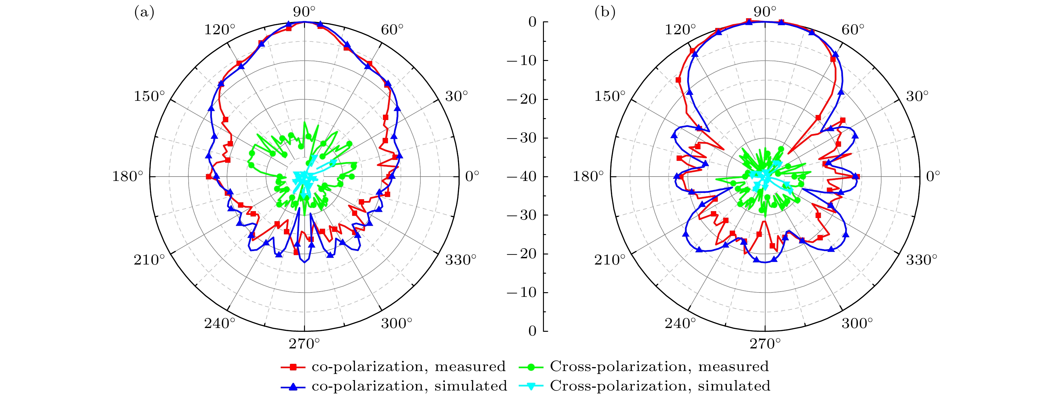
图 13 频率可重构天线27 GHz仿真与实测辐射方向图 (a) E面方向图; (b) H面方向图
Fig. 13. Frequency reconfigurable antenna at 27 GHz simulated and measured radiation pattern: (a) E-plane pattern; (b) H-plane pattern.
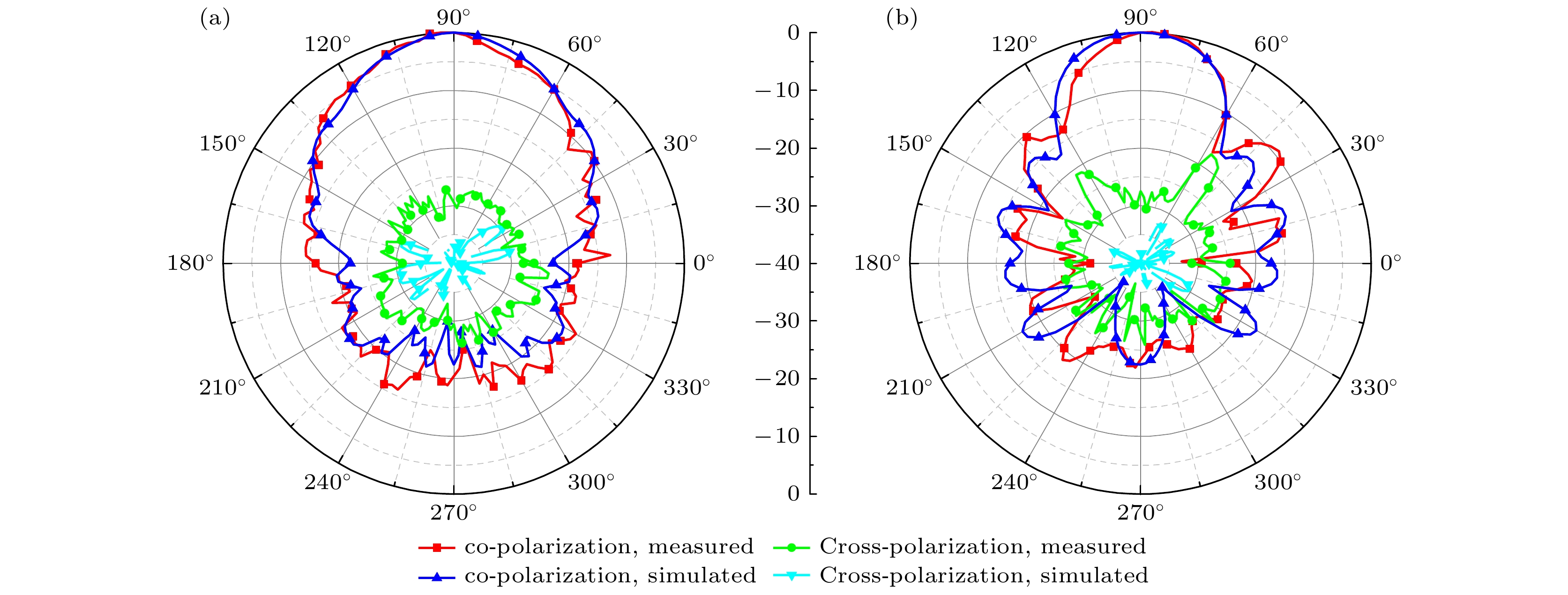
图 14 频率可重构天线35 GHz仿真与实测辐射方向图 (a) E面方向图; (b) H面方向图
Fig. 14. Frequency reconfigurable antenna at 35 GHz simulated and measured radiation pattern: (a) E-plane pattern; (b) H-plane pattern.
表 1 可重构滤波器的结构参数(单位: mm)
Table 1. Structural parameters of the reconfigurable filter (unit: mm).
$ w_0 $ $ w_1 $ $ w_2 $ $ w_3 $ $ w_4 $ $ w_5 $ $ l_1 $ $ l_2 $ $ l_3 $ $ l_4 $ $ l_5 $ $ l_6 $ 0.78 0.30 0.50 0.60 0.60 0.85 0.07 0.07 0.80 0.80 0.40 0.20 $ n_1 $ $ n_2 $ $ n_3 $ $ n_4 $ $ s_0 $ $ s_1 $ $ w_{\rm i} $ $ g_{\rm i} $ $ g_{\rm p} $ $ l_{\rm g} $ $ r $ 1.60 0.20 1.50 0.50 0.10 0.05 0.10 0.10 0.10 0.35 0.10  下载: 导出CSV
表 2 Vivaldi天线结构参数(单位: mm)
Table 2. Structural parameters of the Vivaldi antenna (unit: mm).
$ w_0 $ $ w_1 $ $ w_2 $ $ w_3 $ $ w_4 $ $ l_0 $ $ l_1 $ $ l_2 $ $ l_3 $ $ l_4 $ $ l_5 $ $ l_{\rm S} $ $ d $ $ r $ $ c $ $ h $ 22.00 14.60 0.34 0.24 0.12 33.00 15.00 1.50 1.70 2.15 1.20 3.00 2.00 1.70 0.30 0.254
下载: 导出CSV
表 3 与其他Ka波段频率可重构天线的比较
Table 3. Comparison with other frequency reconfigurable antennas in the Ka-band range.
下载: 导出CSV
-
[1] Yang X J, Ge L, Ji Y, Zeng X R, Luk K M 2019 IEEE Trans. Antennas Propag. 67 6639
Google Scholar
[2] 袁子东, 高军, 曹祥玉, 杨欢欢, 杨群, 李文强, 商楷 2014 63 014102
Google Scholar
Yuan Z D, Gao J, Cao X Y, Yang H H, Yang Q, Li W Q, Shang K 2014 Acta Phys. Sin. 63 014102
Google Scholar
[3] Feng L Y, Leung K W 2016 IEEE Trans. Antennas Propag. 64 340
Google Scholar
[4] Xiang B J, Zheng S Y, Wong H, Pan Y M, Wang K X, Xia M H 2018 IEEE Trans. Antennas Propag. 66 657
Google Scholar
[5] Deng Q J, Pan Y M, Liu X Y, Leung K W 2023 IEEE Trans. Antennas Propag. 71 1971
Google Scholar
[6] Zou J J, Zhao Y, Yang X J, Ge L, Sun Y X 2023 IEEE Antennas Wirel. Propag. Lett. 22 1513
Google Scholar
[7] Chen Q G, Ala-Laurinaho J, Khripkov A, Ilvonen J, Moreno R M, Viikari V 2023 IEEE Trans. Antennas Propag. 71 6628
Google Scholar
[8] Patriotis M, Ayoub F N, Tawk Y, Costantine J, Christodoulou C G 2021 IEEE Antennas Wirel. Propag. Lett. 20 2095
Google Scholar
[9] Kumar Naik K, Sailaja B V S 2024 IEEE Open J. Antennas Propag. 5 673
Google Scholar
[10] Yang W C, Zhou C Y, Xue Q, Wen Q Y, Che W Q 2021 IEEE Trans. Antennas Propag. 69 4359
Google Scholar
[11] 李靖豪, 杨琬琛, 周晨昱, 薛泉, 文岐业, 车文荃 2022 无线电工程 52 317
Google Scholar
Li J H, Yang W C, Zhou C Y, Xue Q, Wen Q Y, Che W Q 2022 Radio Engineering 52 317
Google Scholar
[12] Kim J, Oh J 2020 IEEE Antennas Wirel. Propag. Lett. 19 1958
Google Scholar
[13] Jilani S F, Rahimian A, Alfadhl Y, Alomainy A 2018 Flexible and Printed Electronics 3 1
Google Scholar
[14] Karthika K, Kavitha K, Darsani S, Preethi B, Pavithra P S 2022 8th International Conference on Advanced Computing and Communication Systems (ICACCS) Coimbatore, India, March 25–26, 2022pp907
Google Scholar
[15] Choi J, Park J, Youn Y, Hwang W, Seong H, Whang Y N, Hong W 2020 Trans. Microw. Theory Tech. 68 1872
Google Scholar
[16] Sun W, Liu S X, Zhu X, Zhang X L, Chi P L, Yang T 2022 IEEE Trans. Antennas Propag. 70 156
Google Scholar
[17] Shi Y R, Ni X Y, Qian Z Y, He S J, Feng W J 2023 IEEE Antennas Wirel. Propag. Lett. 22 3097
Google Scholar
[18] Liu Q D, Dong Q, Wen J X, Ye L H, Wu D L, Zhang X Y 2023 IEEE Antennas Wirel. Propag. Lett. 22 2310
Google Scholar
[19] Kuosmanen M, Holopainen J, Ala-Laurinaho J, Kiuru T, Viikari V 2023 IEEE Trans. Antennas Propag. 71 6546
Google Scholar
[20] Guo C G, Zhang Z, Fu X N, Wang J H 2023 IEEE Antennas Wirel. Propag. Lett. 22 1793
Google Scholar
[21] Ma T C, Dang Q H, Fumeaux C, Nguyen-Trong N 2024 IEEE Trans. Antennas Propag. 72 2998
Google Scholar
[22] Tewari N, Dadel M, Srivastava S 2023 IEEE Microwaves, Antennas, and Propagation Conference (MAPCON). Ahmedabad, India, December 11–14, 2023 p1
Google Scholar
[23] Patriotis M, Ayoub F N, Tawk Y, Costantine J, Christodoulou C G 2021 IEEE Open J. Antennas Propag. 2 759
Google Scholar
[24] 邹晓鋆, 许旭光, 康国钦, 朱航, 谭铭, 宋伟 2023 电子与信息学报 45 3973
Google Scholar
Zou X J, Xu X G, Kang G Q, Zhu H, Tan M, Song W 2023 J Electron. Inf. Techn. 45 3973
Google Scholar
[25] Mandal M K, Sanyal S 2006 IEEE Microw. Wirel. Compon. Lett. 16 597
Google Scholar
[26] Lu J C, Liao C K, Chang C Y 2008 Trans. Microw. Theory Tech. 56 2101
Google Scholar
[27] Tu W H 2010 IEEE Microw. Wirel. Compon. Lett. 20 208
Google Scholar
[28] 冯丽君 2022 硕士学位论文 (四川: 电子科技大学)
Feng L J 2022 M. S. Thesis (Chengdu: University of Electronic Science and Technology of China
[29] March S L 1985 Trans. Microw. Theory Tech. 3 269
Google Scholar
[30] Xu J, Wu W, Kang W, Miao C 2012 IEEE Microw. Wirel. Compon. Lett. 22 351
Google Scholar
[31] Wan F Y, Wu L L, Ravelo B, Ge J X 2020 IEEE Trans. Electromagn Compat. 62 1813
Google Scholar
[32] Jiang W, Che W Q 2012 IEEE Antennas Wirel. Propag. Lett. 11 293
Google Scholar

 下载:
下载:


计量
- 文章访问数: 2246
- PDF下载量: 57
- 被引次数: 0
