-
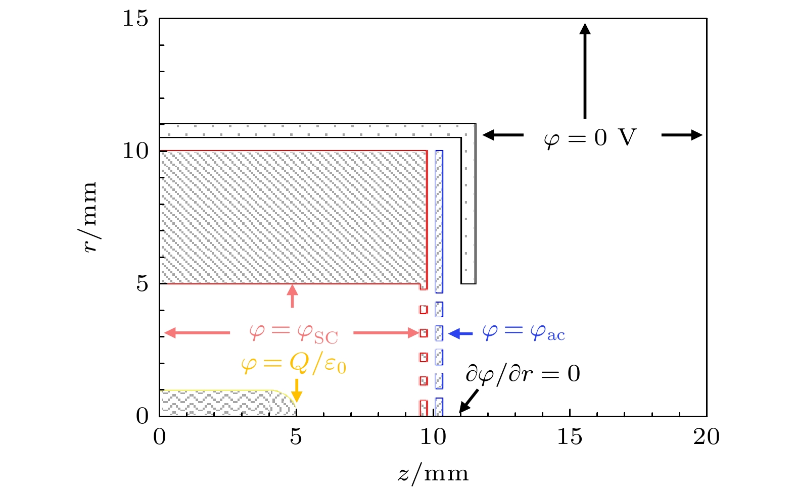
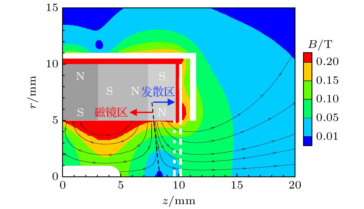
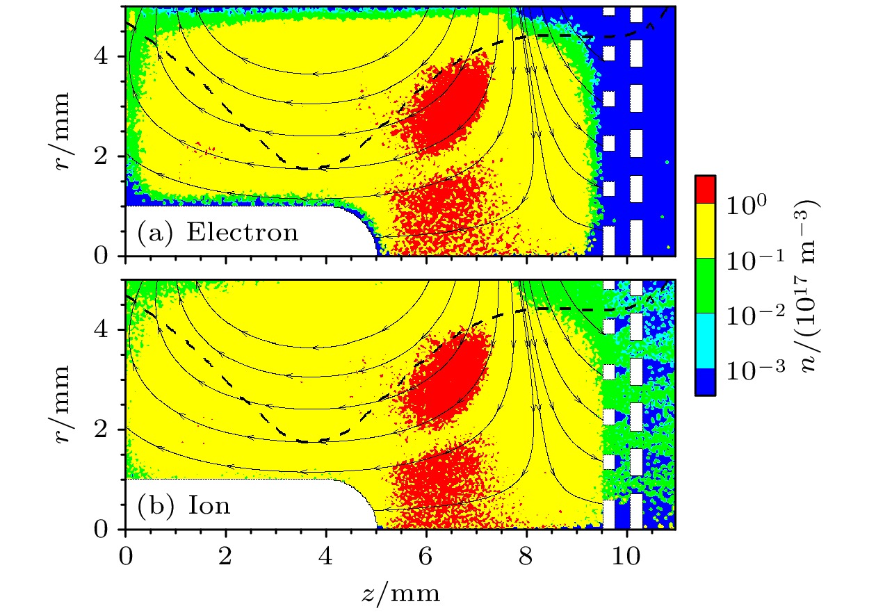
在微波离子推力器的磁场结构设计中, 一般认为增大磁镜区的面积能够约束更多电子, 有利于提高能量利用率; 减小发散区面积能够减少电子在壁面的损失, 有利于降低放电损耗. 随着一体化仿真研究深入, 发现利用Child-Langmuir鞘层的特性可约束电子, 使其在鞘层与磁镜间往复运动获能. 对此, 本文设计了适用于1 cm磁阵列微波离子推力器的磁场结构, 并对其初始放电和束流引出过程进行了一体化仿真, 对比阐明了电子在磁场发散区受Child-Langmuir鞘层、天线表面鞘层和磁镜共同约束下的获能模式. 该获能模式可提升磁场发散区的电子温度, 促进电离, 提升栅极前等离子体密度, 进而提升束流密度. 仿真结果表明, 在氙气流量0.3 sccm (1 sccm= 1 mL/min), 微波功率为1 W, 栅极电压
$ {\varphi }_{{\mathrm{s}}{\mathrm{c}}}/{\varphi }_{{\mathrm{a}}{\mathrm{c}}} $ = 300 V/–50 V条件下, 磁阵列微波离子推力器的电流密度较2 cm微波离子推力器提升57.9%. 本文从理论上对磁场发散区电子加热模式进行了验证, 研究结果将为微波离子推力器优化设计提供理论依据, 促进微波离子推力器性能提升.In magnetic field design principle of microwave discharge ion thruster, it is universally received that enlarging the magnetic mirror region can confine more electrons to acquire better energy utilization rate, while reducing the magnetic field diffusion region can prevent electrons from losing at wall to reduce the discharge loss. However, recently the integrated simulation proposes a hypothesis that electrons can also be heated in the magnetic field diffusion region when the Child-Langmuir sheath is considered as a constraint condition for electrons. Therefore, herein a magnetic field structure for the magnet array microwave discharge ion thruster is designed to verify the hypothesis, in which the magnetic field diffusion region is located near the screen grid. Then, an integrated simulation is conducted for studying the initial discharge and ion beam extraction stages of the thruster. The simulation results show that in the magnetic field diffusion region, the electron temperature is 4–8 eV when the grid system voltage is not applied, while the electron temperature is 4–12 eV when the the grid system voltage is applied. And the plasma density in the latter case has one order of magnitude higher than that in the former case. It means that electrons are obviously heated in the magnetic field diffusion region when they are confined among the Child-Langmuir sheath, the plasma sheath at antenna surface, and magnetic mirror. This electron heating mode produces more high-energy electrons outside the magnetic mirror region to generate plasma in front of the grid system, which can significantly increase the plasma density and ion beam current density. The result shows that under the conditions of 0.3 sccm (1 sccm = 1 mL/min) xenon gas flow, 1 W input microwave power, 300 V screen grid voltage and –50 V acceleration grid voltage, the ion beam current and its density are 0.47 mA and 0.60 mA/cm2 for the magnet array microwave discharge ion thruster, while the ion beam current and its density are 1.2 mA and 0.38 mA/cm2 for the 2-cm microwave discharge ion thruster. The ion beam current density increases by 57.9%. Through the integrated simulation, a new electron heating mode in the magnetic field diffusion region is proved theoretically, which provides a theoretical basis for the magnetic field structure optimization of microwave discharge ion thruster.-
Keywords:
- electron cyclotron resonance /
- ion thruster /
- electron confining /
- electron heating
[1] 杨涓, 牟浩, 耿海, 吴先明 2023 推进技术 44 78
 Google Scholar
Yang J, Mou H, Geng H, Wu X M 2023 J. Propuls. Tech. 44 78
 Google Scholar
[2] Watanabe S, Tsuda Y, Yoshikawa M, Tanaka S, Saiki T, Nakazawa S 2017 Space Sci. Rev. 208 3
 Google Scholar
[3] Koizumi H, Kawahara H, Yaginuma K, et al. 2016 Trans. JSASS Aerospace Tech. Jpn. 14 30
 Google Scholar
[4] 韩罗峰, 朱康武, 黄文斌, 于学文, 张辰乙, 鲁超, 刘通, 李航, 黄静 2022 真空与低温 28 98
 Google Scholar
Han L F, Zhu K W, Huang W B, Yu X W, Zhang C Y, Lu C, Liu T, Li H, Huang J 2022 Vacuum Cry. 28 98
 Google Scholar
[5] 于达仁, 乔磊, 蒋文嘉, 刘辉 2020 推进技术 41 1
 Google Scholar
Yu D R, Qiao L, Jiang W J, Liu H 2020 J. Propuls. Tech. 41 1
 Google Scholar
[6] Tsukizaki R, Ise T, Koizumi H, Togo H, Nishiyama K, Kuninaka H 2014 J. Propul. Power 30 5
 Google Scholar
[7] 夏旭, 杨涓, 金逸舟, 杭观荣, 付瑜亮, 胡展 2019 68 235202
 Google Scholar
Xia X, Yang J, Jin Y Z, Hang G R, Fu Y L, Hu Z 2019 Acta Phys. Sin. 68 235202
 Google Scholar
[8] Fu S H, Ding Z F, Ke Y J, Tian L C 2020 IEEE Trans. Plasma Sci. 48 3
 Google Scholar
[9] Ke Y J, Sun X F, Zhao Y, Chen X K 2018 Prog. Electromagn. Res. Lett. 75 91
 Google Scholar
[10] Dey I, Toyoda Y, Yamamoto N, Nakashima H 2015 Rev. Sci. Instrum. 86 1868
 Google Scholar
[11] Takao Y, Koizumi H, Komurasaki K, Eriguchi K, Ono K 2014 Plasma Sources Sci. Technol. 23 064004
 Google Scholar
[12] Tani Y, Yamashita Y, Tsukizaki R, Nishiyama K, Kuninaka H 2020 Acta Astronau. 176 77
 Google Scholar
[13] Ataka Y, Nakagawa Y, Koizumi H, Komurasaki K 2021 Acta Astronau. 187 133
 Google Scholar
[14] Xia X, Yang J, Jin Y Z, Hang G R, Fu Y L, Hu Z 2020 Vacuum 179 109517
 Google Scholar
[15] Mou H, Jin Y Z, Yang J, Xia X, Fu Y L 2022 Chin. Phys. B 31 075202
 Google Scholar
[16] Coral G, Tsukizaki, Nishiyama K, Kuninaka H 2018 Plasma Sources Sci. Technol. 27 095015
 Google Scholar
[17] Koizumi H, Komurasaki K, Aoyama J, Yamaguchi K 2018 J. Propul. Power 34 4
 Google Scholar
[18] Motoki T, Takasaki D, Koizumi H, Ataka Y, Komurasaki K, Takao Y 2022 Acta Astronau. 196 231
 Google Scholar
[19] 夏旭 2022 博士学位论文(西安: 西北工业大学)
Xia X 2022 Ph. D. Dissertation (Xi’an: Northwestern Polytechnical University
[20] 付瑜亮, 杨涓, 夏旭, 孙安邦 2023 72 175204
 Google Scholar
Fu Y L, Yang J, Xia X, Sun A B 2023 Acta Phys. Sin. 72 175204
 Google Scholar
[21] 付瑜亮 2022 博士学位论文(西安: 西北工业大学)
Fu Y L 2022 Ph. D. Dissertation (Xi’an: Northwestern Polytechnical University
[22] Fu Y L, Yang J, Mou H, Tan R W, Xia X, Gao Z Y 2022 Comput. Phys. Commun. 278 8395
 Google Scholar
-
-
[1] 杨涓, 牟浩, 耿海, 吴先明 2023 推进技术 44 78
 Google Scholar
Yang J, Mou H, Geng H, Wu X M 2023 J. Propuls. Tech. 44 78
 Google Scholar
[2] Watanabe S, Tsuda Y, Yoshikawa M, Tanaka S, Saiki T, Nakazawa S 2017 Space Sci. Rev. 208 3
 Google Scholar
[3] Koizumi H, Kawahara H, Yaginuma K, et al. 2016 Trans. JSASS Aerospace Tech. Jpn. 14 30
 Google Scholar
[4] 韩罗峰, 朱康武, 黄文斌, 于学文, 张辰乙, 鲁超, 刘通, 李航, 黄静 2022 真空与低温 28 98
 Google Scholar
Han L F, Zhu K W, Huang W B, Yu X W, Zhang C Y, Lu C, Liu T, Li H, Huang J 2022 Vacuum Cry. 28 98
 Google Scholar
[5] 于达仁, 乔磊, 蒋文嘉, 刘辉 2020 推进技术 41 1
 Google Scholar
Yu D R, Qiao L, Jiang W J, Liu H 2020 J. Propuls. Tech. 41 1
 Google Scholar
[6] Tsukizaki R, Ise T, Koizumi H, Togo H, Nishiyama K, Kuninaka H 2014 J. Propul. Power 30 5
 Google Scholar
[7] 夏旭, 杨涓, 金逸舟, 杭观荣, 付瑜亮, 胡展 2019 68 235202
 Google Scholar
Xia X, Yang J, Jin Y Z, Hang G R, Fu Y L, Hu Z 2019 Acta Phys. Sin. 68 235202
 Google Scholar
[8] Fu S H, Ding Z F, Ke Y J, Tian L C 2020 IEEE Trans. Plasma Sci. 48 3
 Google Scholar
[9] Ke Y J, Sun X F, Zhao Y, Chen X K 2018 Prog. Electromagn. Res. Lett. 75 91
 Google Scholar
[10] Dey I, Toyoda Y, Yamamoto N, Nakashima H 2015 Rev. Sci. Instrum. 86 1868
 Google Scholar
[11] Takao Y, Koizumi H, Komurasaki K, Eriguchi K, Ono K 2014 Plasma Sources Sci. Technol. 23 064004
 Google Scholar
[12] Tani Y, Yamashita Y, Tsukizaki R, Nishiyama K, Kuninaka H 2020 Acta Astronau. 176 77
 Google Scholar
[13] Ataka Y, Nakagawa Y, Koizumi H, Komurasaki K 2021 Acta Astronau. 187 133
 Google Scholar
[14] Xia X, Yang J, Jin Y Z, Hang G R, Fu Y L, Hu Z 2020 Vacuum 179 109517
 Google Scholar
[15] Mou H, Jin Y Z, Yang J, Xia X, Fu Y L 2022 Chin. Phys. B 31 075202
 Google Scholar
[16] Coral G, Tsukizaki, Nishiyama K, Kuninaka H 2018 Plasma Sources Sci. Technol. 27 095015
 Google Scholar
[17] Koizumi H, Komurasaki K, Aoyama J, Yamaguchi K 2018 J. Propul. Power 34 4
 Google Scholar
[18] Motoki T, Takasaki D, Koizumi H, Ataka Y, Komurasaki K, Takao Y 2022 Acta Astronau. 196 231
 Google Scholar
[19] 夏旭 2022 博士学位论文(西安: 西北工业大学)
Xia X 2022 Ph. D. Dissertation (Xi’an: Northwestern Polytechnical University
[20] 付瑜亮, 杨涓, 夏旭, 孙安邦 2023 72 175204
 Google Scholar
Fu Y L, Yang J, Xia X, Sun A B 2023 Acta Phys. Sin. 72 175204
 Google Scholar
[21] 付瑜亮 2022 博士学位论文(西安: 西北工业大学)
Fu Y L 2022 Ph. D. Dissertation (Xi’an: Northwestern Polytechnical University
[22] Fu Y L, Yang J, Mou H, Tan R W, Xia X, Gao Z Y 2022 Comput. Phys. Commun. 278 8395
 Google Scholar
计量
- 文章访问数: 3628
- PDF下载量: 92
- 被引次数: 0


 下载:
下载:


