-
在磁约束聚变等离子体中, 离子回旋共振加热(ICRF)与中性束注入(NBI)是两种主要的加热方法. 它们的协同加热一直都是聚变领域研究的重点. 本文首先阐明了ICRF高次谐波加热以及ICRF与NBI协同加热的基本原理. 通过EAST托卡马克上实验和相应的TRANSP模拟, 发现了ICRF与NBI的协同加热不仅可以显著提高等离子体参数(极向比压、等离子体储能、离子温度、中子产额等), 而且能产生大量高能粒子, 形成高能粒子尾巴. 例如, 1 MW的ICRF三次谐波可将初始能量为60 keV的NBI高能氘离子加速至600 keV. 通过改变氢少子含量、提高ICRF和NBI加热功率、使用ICRF在轴加热、优化NBI注入角度等, 可以有效地提高协同加热效率以及高能粒子的能量. 进一步地, 将协同加热产生的高能粒子分布代入粒子轨道程序中, 计算了高能粒子的输运以及其在第一壁上的损失. 结果表明, 损失的高能粒子的初始位置位于低场侧, 且损失轨道大部分为捕获粒子轨道. 高能粒子损失位置主要位于主限制器以及ICRF和低杂波限制器的中上平面. 这些损失的高能粒子被认为是造成限制器上热斑的主要原因之一.In magnetic confinement fusion plasmas, radio-frequency wave heating in the ion cyclotron range of frequencies (ICRF) and neutral beam injection (NBI) are two main heating methods. Their synergetic heating has long been a key topic in fusion research. In this work, we clarify the basic principles of ICRF high harmonic heating and the synergetic heating between ICRF and NBI. Then, we perform a series of experiments on EAST tokamak and carry out the corresponding TRANSP simulations. The results indicate that the ICRF-NBI synergetic heating not only significantly increases the plasma parameters (including poloidal beta, plasma stored energy, ion temperature and neutron yield), but also generates a large number of energetic particles and develops an energetic particle tail in its distribution function. For instance, the ICRF third harmonic heating with 1 MW of power can increase the energy of NBI fast ions from 60 to 600 keV. By changing the hydrogen minority concentration, improving the ICRF and NBI heating power, using the on-axis ICRF heating or optimizing the NBI injection angle, the ICRF-NBI synergetic heating effect can be further enhanced, accompanied with an increase of fast ion energy. Moreover, by using the fast ion distribution as input in the orbit tracing code, the transport and loss of energetic particles are calculated. The results show that the initial positions of the lost energetic particles are on the low field side, and their orbits are mainly trapped orbits. The loss of energetic particles is mainly located in the middle and upper plane of the main limiter, ICRF and LH antenna limiters. The lost of these energetic particles are considered as one of the main reasons why hot spots occur on the limiters.
-
Keywords:
- ion cyclotron resonance heating /
- neutral beam injection /
- synergetic heating /
- fast ion distribution
[1] Ongena J, Kazakov Y O, Baranov, et al. 2017 EPJ Web of Conferences 157 02006
 Google Scholar
[2] Gallart D, Mantsinen M J, Challis C, et al. 2018 Nucl. Fusion 58 106037
 Google Scholar
[3] Bilato R, Brambilla M, Maj O, et al. 2011 Nucl. Fusion 51 103034
 Google Scholar
[4] Tardini G, Bilato R, Fischer R, et al. 2019 Nucl. Fusion 59 046002
 Google Scholar
[5] Choi M, Chan V S, Chiu S C, et al. 2003 AIP Conference Proceedings 694 86
 Google Scholar
[6] Koch R, Van Wassenhove G, Van Eester D, et al. 1995 Plasma Phys. Control. Fusion 37 A291
 Google Scholar
[7] Kimura H, Fujii T, Tobita K, et al. 1991 Nucl. Fusion 31 83
 Google Scholar
[8] Hamamatsu K, Azumi M, Kishimoto Y, et al. 1989 Nucl. Fusion 29 147
 Google Scholar
[9] Yamagiwa M, Kishimoto Y, Fujii T, et al. 1993 Nucl. Fusion 33 493
 Google Scholar
[10] Hellesen C, Mantsinen M, Conroy S, et al. 2018 Nucl. Fusion 58 056021
 Google Scholar
[11] Eriksson J, Nocente M, Binda F, et al. 2015 Nucl. Fusion 55 123026
 Google Scholar
[12] Salewski M, Nocente M, Jacobsen A S, et al. 2017 Nucl. Fusion 57 056001
 Google Scholar
[13] Mantsinen M J, Mayoral M L, Van Eester D, et al. 2004 Nucl. Fusion 44 33
 Google Scholar
[14] Van Eester D, Lerche E, Andrew Y, et al. 2009 Plasma Phys. Control. Fusion 51 044007
 Google Scholar
[15] Kazakov Y O, Nocente M, Mantsinen M J, et al. 2020 Nucl. Fusion 60 112013
 Google Scholar
[16] Weiland M, Bilato R, Geiger B, et al. 2017 Nucl. Fusion 57 116058
 Google Scholar
[17] Start D, Adams J M, Ageladarakis P, et al. 1998 Plasma Phys. Control. Fusion 40 A87
 Google Scholar
[18] Zhang W, Zhu G H, Zhang X J, et al. 2023 Nucl. Fusion 63 056015
 Google Scholar
[19] Jacquinot J, the JET team 1999 Plasma Phys. Control. Fusion 41 A13
 Google Scholar
[20] Gibney E 2022 Nature 602 371
 Google Scholar
[21] Stix T H 1975 Nucl. Fusion 15 737
 Google Scholar
[22] He K, Sun Y, Wan B N, et al. 2021 Nucl. Fusion 61 016009
 Google Scholar
[23] Zheng Y F, Xiao J Y, Wang Y P, et al. 2021 Chin. Phys. B 30 095201
 Google Scholar
[24] White R B 1990 Phys. Fluids B 2 845
 Google Scholar
[25] Mynick H E 1993 Phys. Fluids B 5 1471
 Google Scholar
-
图 2 (a) 高次谐波对应的环向磁场. 其中n来自方程(2), 代表第n次谐波加热, 虚线为EAST磁轴R0 = 1.92 m处; (b) 当环向磁场Bt = 1.63 T时n = 2—4次谐波共振所在位置; (c) EAST上四条NBI束线和两个ICRF天线的环向位置
Fig. 2. (a) Toroidal magnetic field for high harmonic ICRF heating. The integer n comes from Eq. (2) and represents the nth high harmonic heating. The vertical dashed line represents the magnetic axis at R0 = 1.92 m; (b) high harmonic resonance positions for n = 2–4 with Bt = 1.63 T. (c) toroidal locations of the four NBI lines and two ICRF antennas.
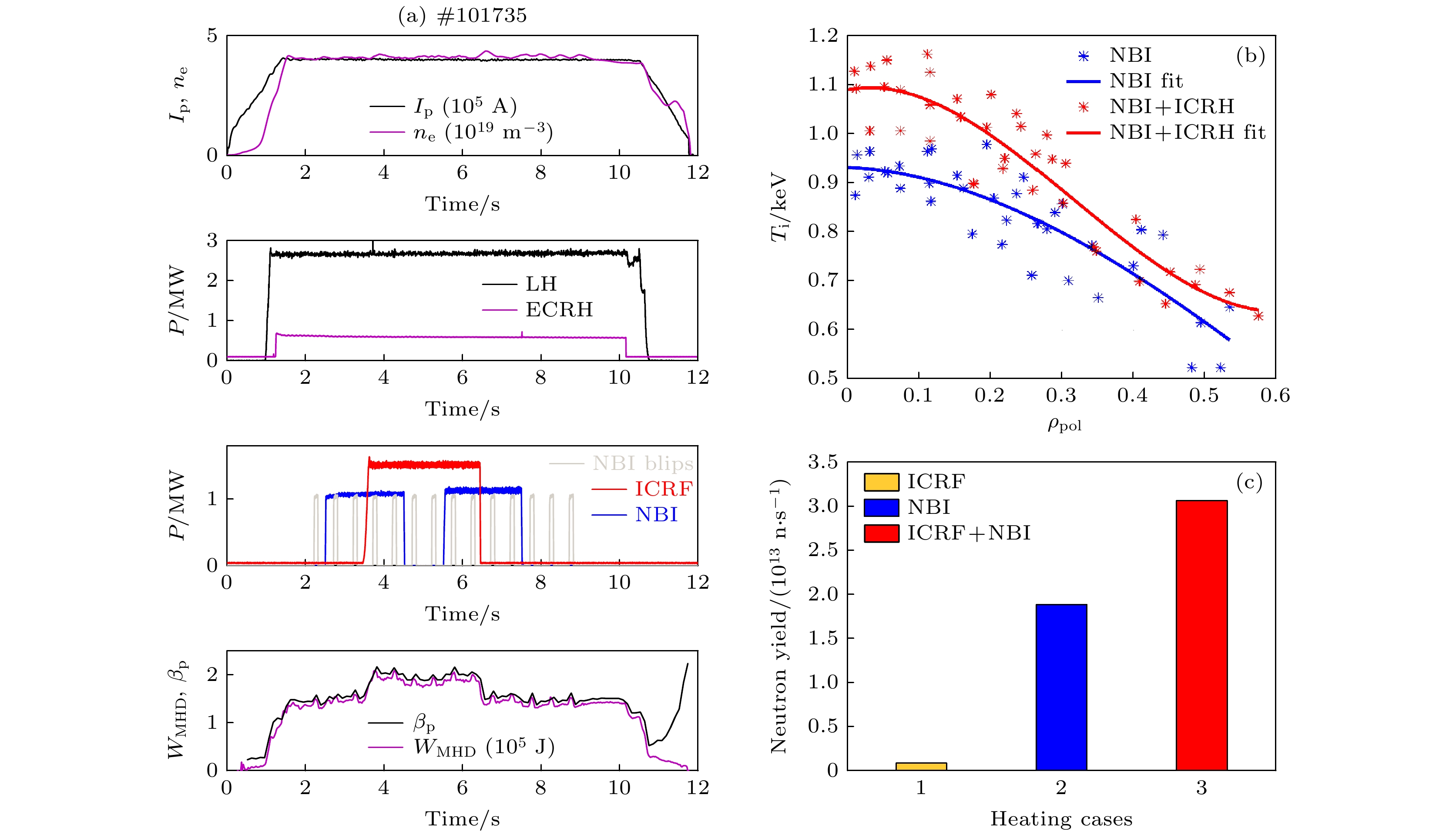
图 3 (a) ICRF二次谐波与NBI协同加热的实验设置; (b) 协同加热对离子温度的影响; (c) 协同加热对中子产额的影响. 图中NBI的功率设置成两个脉冲是为了获得更多的协同加热和NBI单独加热的数据. 设置NBI blips是为了获得FIDA的诊断数据
Fig. 3. (a) Experimental setups of the ICRF second harmonic heating and NBI synergetic heating; (b), (c) influences of synergetic heating on the (b) ion temperature and (c) neutron yield. The NBI heating power is set with two separate pulses in order to obtain more data for cases with synergetic heating and NBI heating alone. The NBI blips is set to facilitate the FIDA diagnostics.
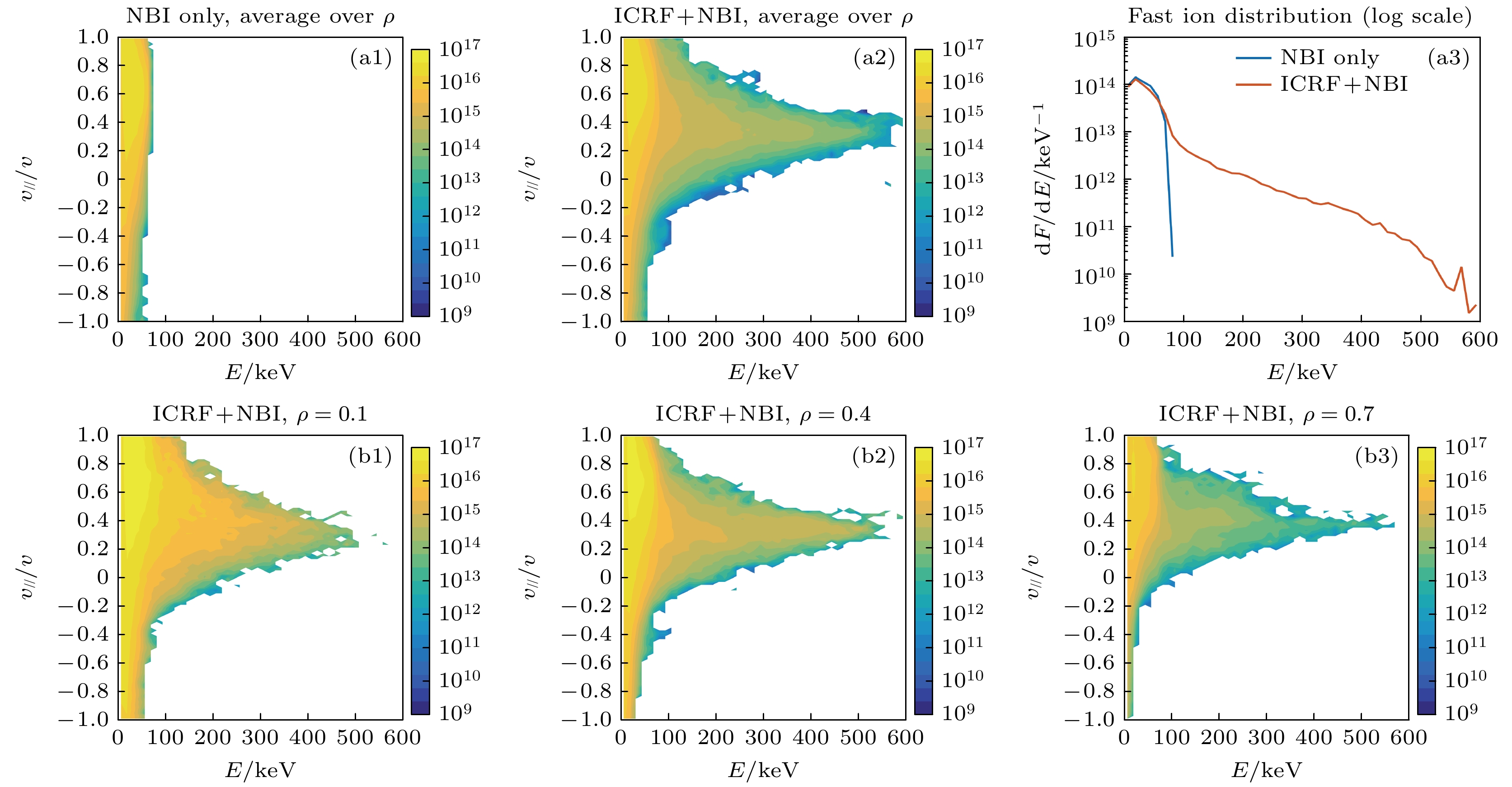
图 5 (a1) 2 MW NBI和(a2) 2 MW NBI + 1 MW ICRF协同加热下的高能氘离子在能量-投掷角上的二维分布以及(a3) 高能氘离子关于能量的一维分布, 其中F是高能氘离子的密度, E是能量; 计算这些分布时对不同径向位置做了平均; (b1)—(b3) 2 MW NBI + 1 MW ICRF协同加热下高能粒子在不同径向位置的分布
Fig. 5. (a1) 2 MW NBI and (a2) 2 MW NBI + 1 MW ICRF synergetic heating induced fast Deuterium ion distribution as a function of the energy and pitch angle and (a3) 1D distribution as a function of energy. (b1)–(b3) 2 MW NBI + 1 MW ICRF synergetic heating induced fast Deuterium ion distribution at different radial locations.
图 6 NBI单独加热(蓝色)及NBI与ICRF协同加热(红色)情况下产生的高能氘离子关于(a) 径向和(b) 投掷角的分布. 图中蓝色和红色重叠区域显示为深红色
Fig. 6. NBI heating alone (blue) and NBI-ICRF synergetic heating (red) induced fast Deuterium ion distribution as a function of (a) radial position and (b) pitch angle. The dark red color in the figure is due to the overlap of the blue and red colors.
图 7 NBI单独加热及NBI与ICRF协同加热情况下产生的氘离子在磁矩-环向动量二维图上的分布, 其中氘离子能量为(a) 60 keV和(b) 100 keV; 可以看出, 当粒子能量不同时, 其粒子分区也不一样
Fig. 7. NBI heating alone and NBI-ICRF synergetic heating induced fast Deuterium ion distribution in the 2D magnetic torque and toroidal momentum map with energy of (a) 60 keV and (b) 100 keV, respectively. It can be inferred from the figure that when the energy of the fast ions are different, their distributions in the 2D map are also different.
图 8 NBI与ICRF协同加热产生的高能氘离子 (a)初始位置(蓝色)与第一壁损失(红色); (b) 在第一壁上的能量沉积; (c) 实验上观测到的
$ {\rm D}_{\text{α}} $ 信号. 其中, 在SOFT和ISSDE模拟计算中都只考虑了碰撞和环向波纹场Fig. 8. (a) Initial position (blue) and first wall loss (red) of the NBI-ICRF synergetic heating induced fast Deuterium ions; (b) power deposition of the fast ions on the first wall and its comparison with (c) observed
$ {\rm D}_{\text{α}}$ signal in experiments. Here, both collision and toroidal field ripple are considered in the SOFT and ISSDE calculations.图 9 单个高能D离子(E = 60 keV)在(a)无磁扰动, (b)有磁扰动, (c)有磁扰动和环向波纹场时的粒子导心轨道
Fig. 9. Guiding center orbit of a fast Deuterium ion with energy of E = 60 keV in the presence of (a) no magnetic field perturbation, (b) magnetic field perturbation, (c) both magnetic field perturbation and toroidal magnetic field ripple.
-
[1] Ongena J, Kazakov Y O, Baranov, et al. 2017 EPJ Web of Conferences 157 02006
 Google Scholar
[2] Gallart D, Mantsinen M J, Challis C, et al. 2018 Nucl. Fusion 58 106037
 Google Scholar
[3] Bilato R, Brambilla M, Maj O, et al. 2011 Nucl. Fusion 51 103034
 Google Scholar
[4] Tardini G, Bilato R, Fischer R, et al. 2019 Nucl. Fusion 59 046002
 Google Scholar
[5] Choi M, Chan V S, Chiu S C, et al. 2003 AIP Conference Proceedings 694 86
 Google Scholar
[6] Koch R, Van Wassenhove G, Van Eester D, et al. 1995 Plasma Phys. Control. Fusion 37 A291
 Google Scholar
[7] Kimura H, Fujii T, Tobita K, et al. 1991 Nucl. Fusion 31 83
 Google Scholar
[8] Hamamatsu K, Azumi M, Kishimoto Y, et al. 1989 Nucl. Fusion 29 147
 Google Scholar
[9] Yamagiwa M, Kishimoto Y, Fujii T, et al. 1993 Nucl. Fusion 33 493
 Google Scholar
[10] Hellesen C, Mantsinen M, Conroy S, et al. 2018 Nucl. Fusion 58 056021
 Google Scholar
[11] Eriksson J, Nocente M, Binda F, et al. 2015 Nucl. Fusion 55 123026
 Google Scholar
[12] Salewski M, Nocente M, Jacobsen A S, et al. 2017 Nucl. Fusion 57 056001
 Google Scholar
[13] Mantsinen M J, Mayoral M L, Van Eester D, et al. 2004 Nucl. Fusion 44 33
 Google Scholar
[14] Van Eester D, Lerche E, Andrew Y, et al. 2009 Plasma Phys. Control. Fusion 51 044007
 Google Scholar
[15] Kazakov Y O, Nocente M, Mantsinen M J, et al. 2020 Nucl. Fusion 60 112013
 Google Scholar
[16] Weiland M, Bilato R, Geiger B, et al. 2017 Nucl. Fusion 57 116058
 Google Scholar
[17] Start D, Adams J M, Ageladarakis P, et al. 1998 Plasma Phys. Control. Fusion 40 A87
 Google Scholar
[18] Zhang W, Zhu G H, Zhang X J, et al. 2023 Nucl. Fusion 63 056015
 Google Scholar
[19] Jacquinot J, the JET team 1999 Plasma Phys. Control. Fusion 41 A13
 Google Scholar
[20] Gibney E 2022 Nature 602 371
 Google Scholar
[21] Stix T H 1975 Nucl. Fusion 15 737
 Google Scholar
[22] He K, Sun Y, Wan B N, et al. 2021 Nucl. Fusion 61 016009
 Google Scholar
[23] Zheng Y F, Xiao J Y, Wang Y P, et al. 2021 Chin. Phys. B 30 095201
 Google Scholar
[24] White R B 1990 Phys. Fluids B 2 845
 Google Scholar
[25] Mynick H E 1993 Phys. Fluids B 5 1471
 Google Scholar
计量
- 文章访问数: 8403
- PDF下载量: 246
- 被引次数: 0


 下载:
下载:


