-
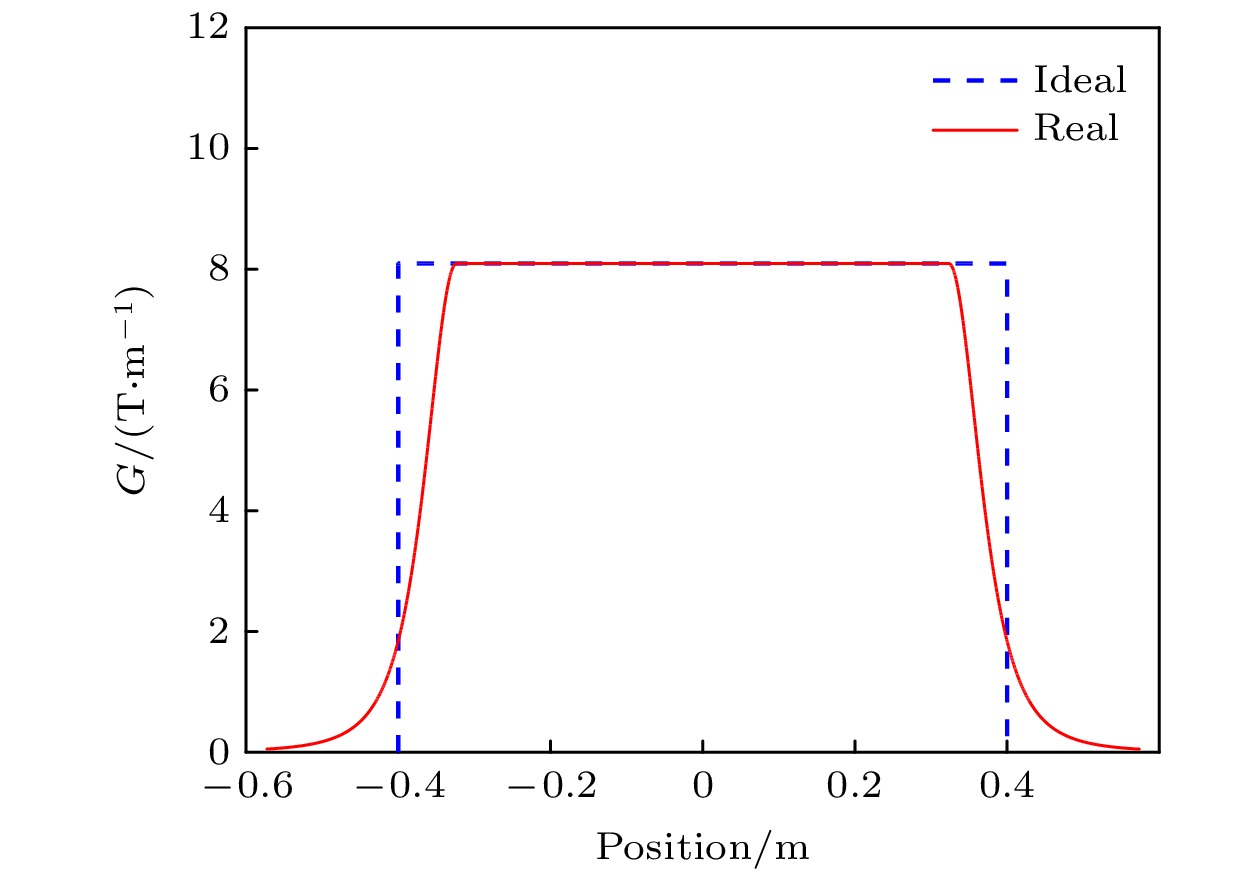
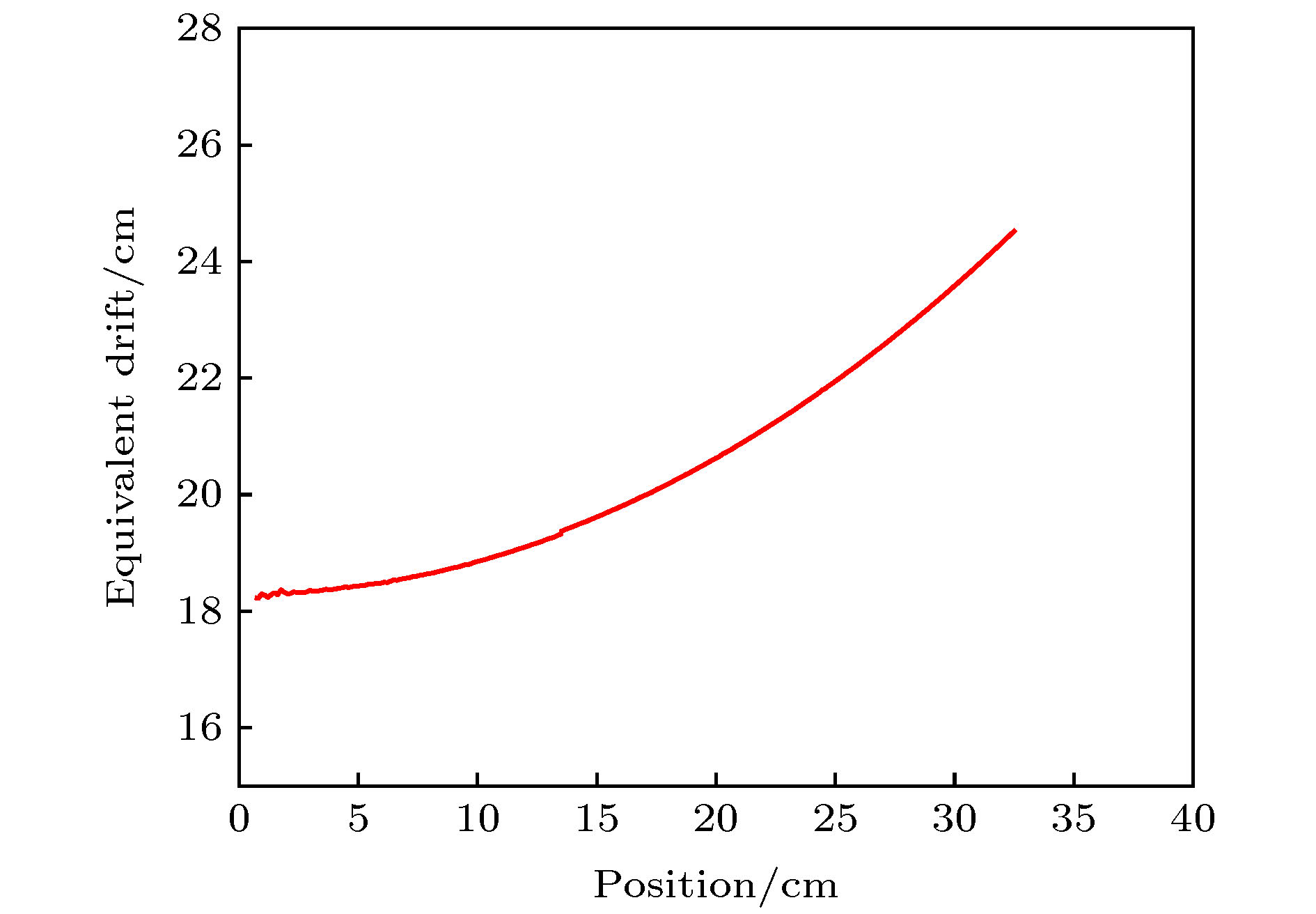
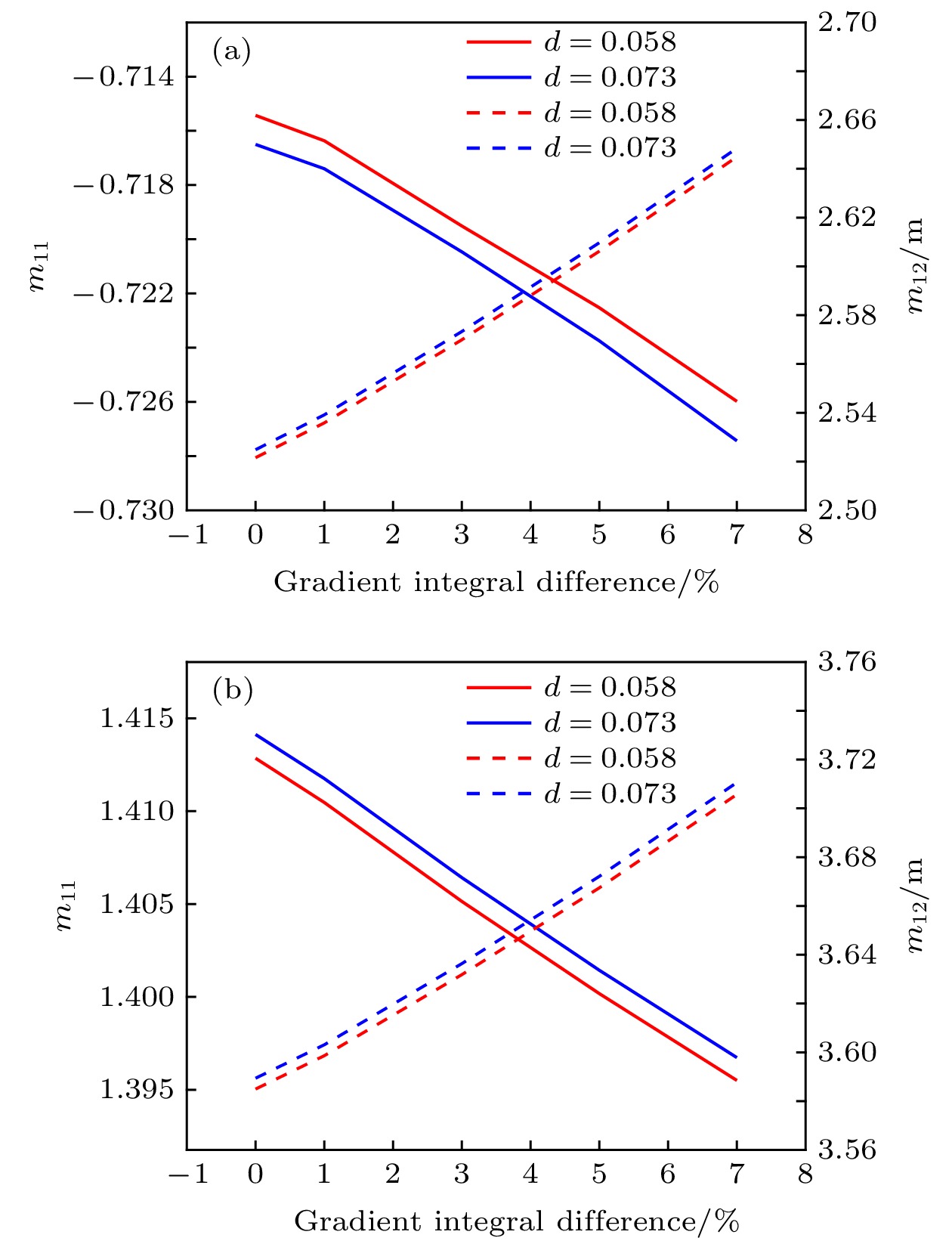
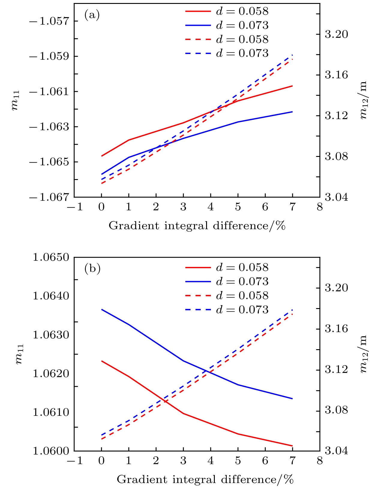
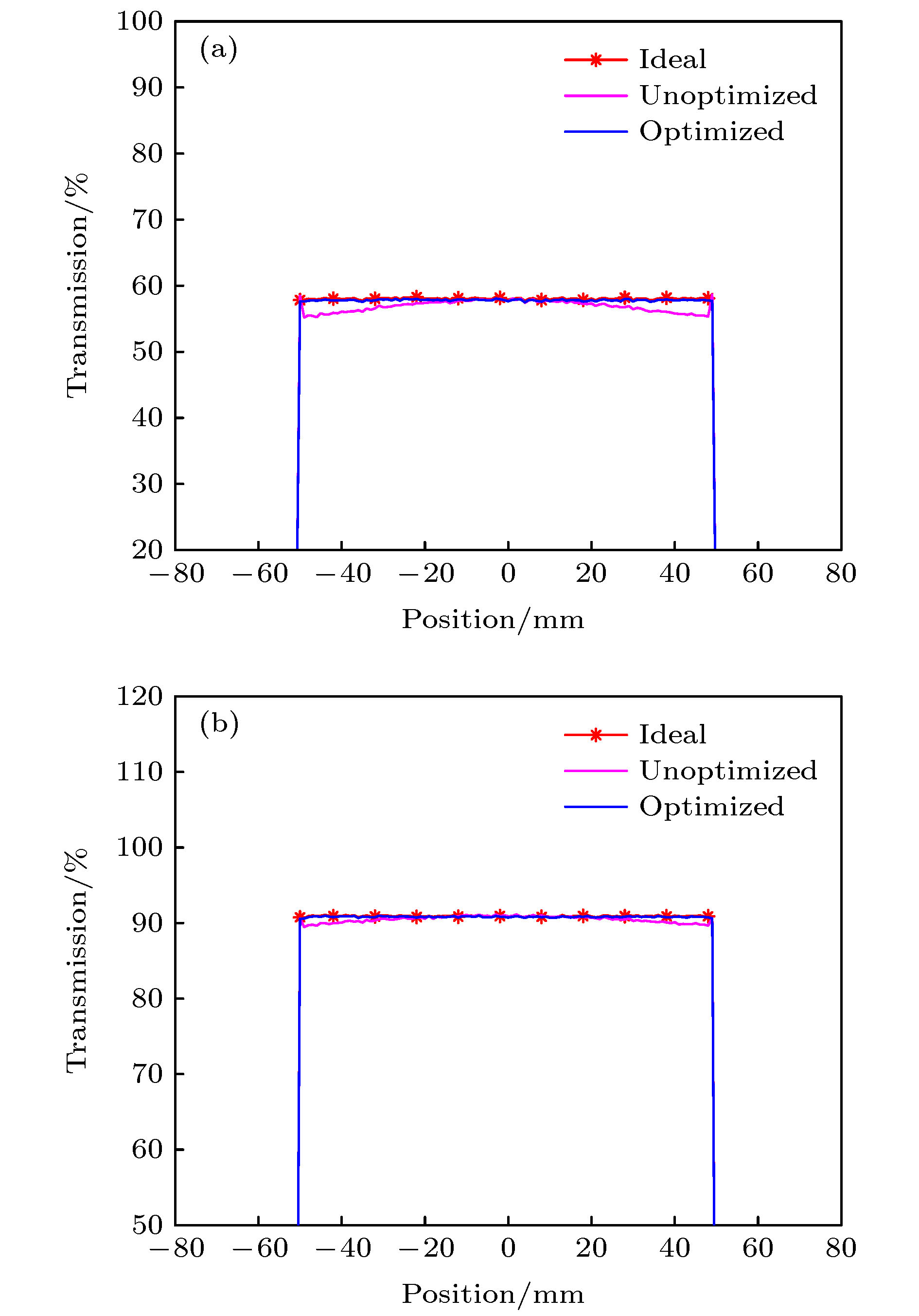
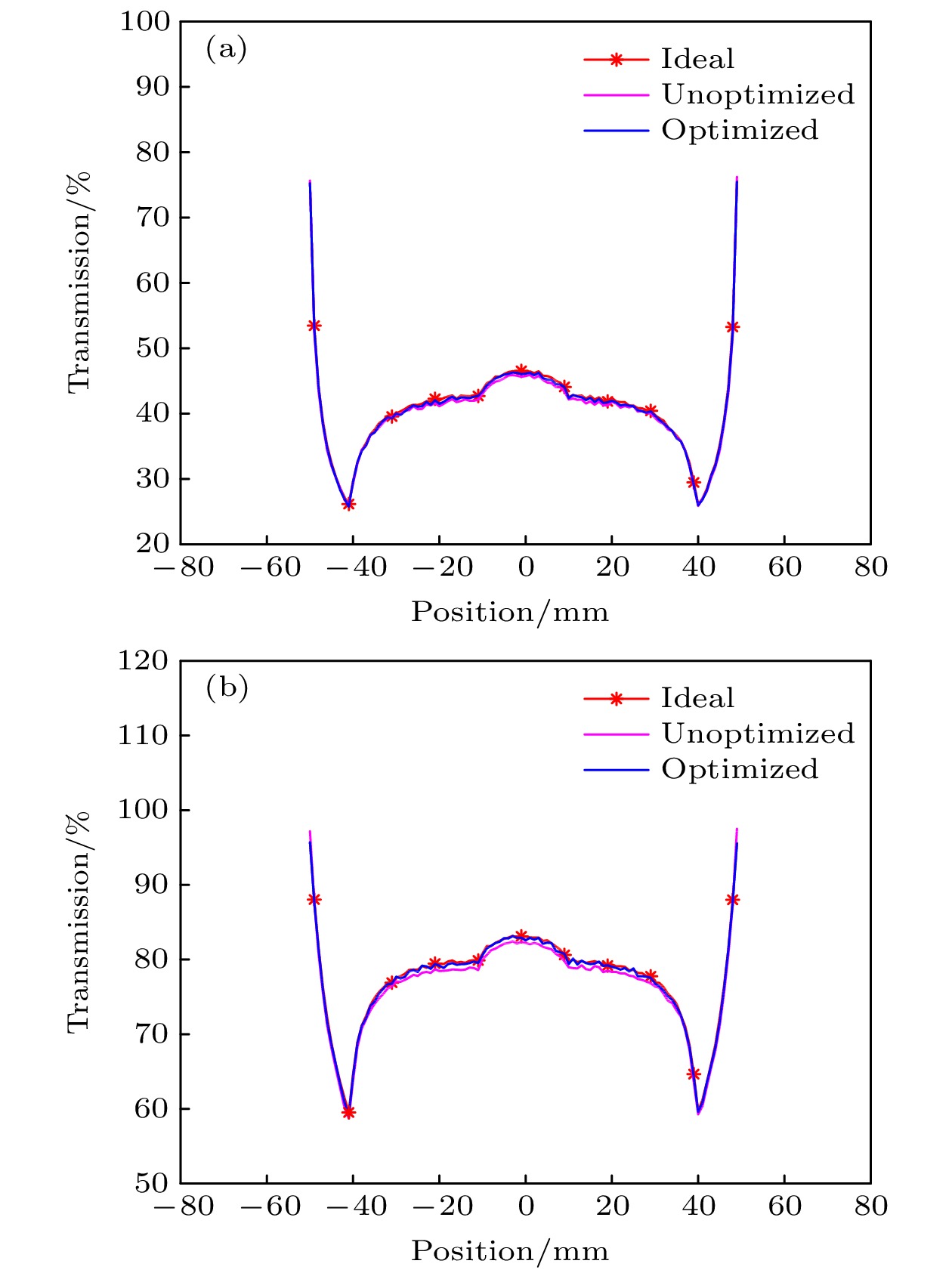
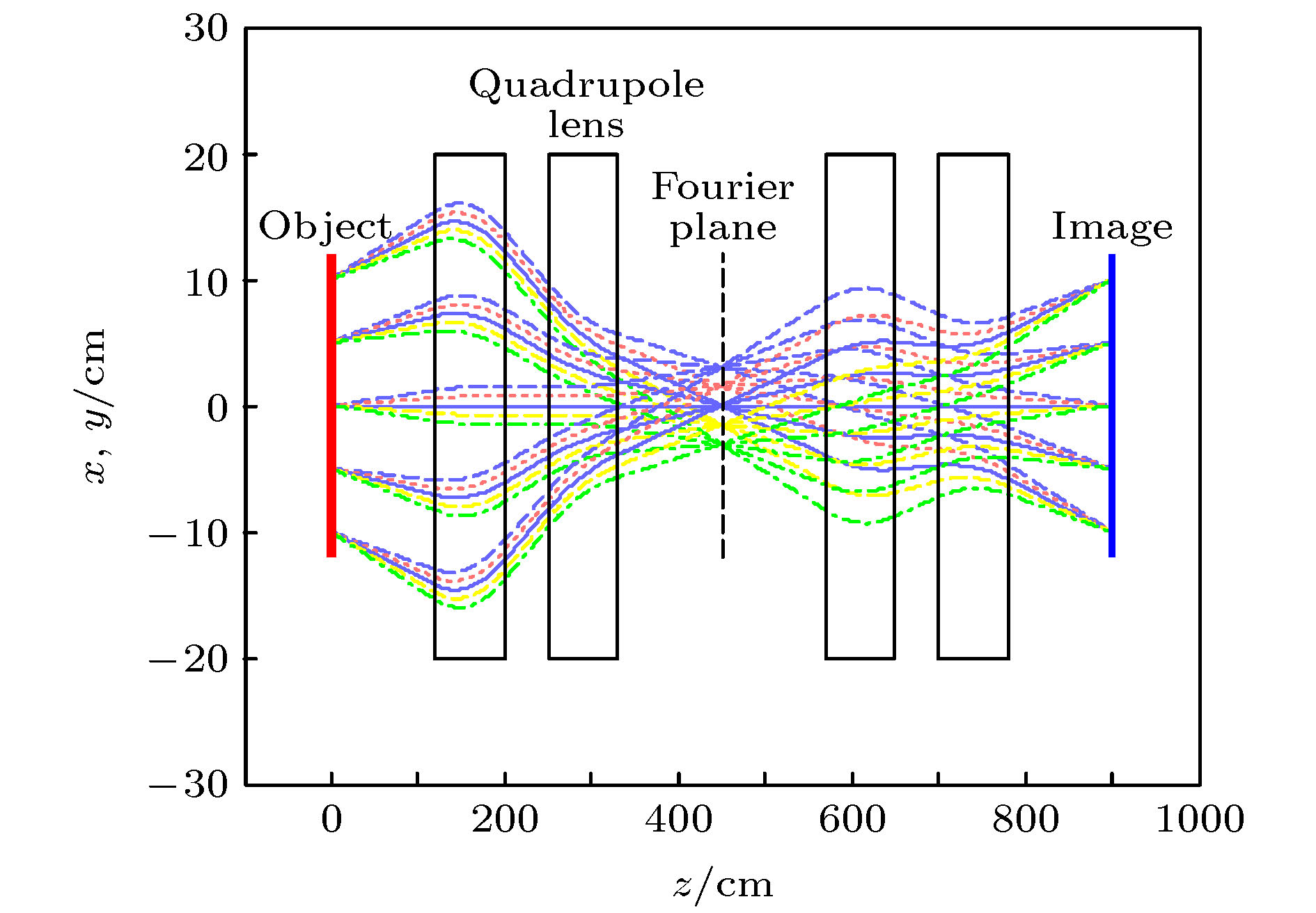
高能质子照相系统由四极磁透镜和准直器组成, 实际透镜的边缘场将影响成像系统的性能. 本文将含边缘场的磁场梯度用贝尔函数近似, 提出了一种含边缘场的成像系统优化方法. 通过Geant 4程序模拟了能量为1.6 GeV的质子成像系统, 并通过优化方法给出了考虑边缘场的优化后的系统参数. 研究了考虑边缘场时的成像系统参数对准直器孔径的影响. 通过对比理想成像系统和优化前后的成像系统在使用准直器时的客体通量分布, 研究了边缘场对质子通过客体的通量影响. 结果表明, 优化后的成像系统可以减小质子通过客体后的通量误差, 并且积分差值在10–2量级时, 准直器的孔径参数变化亦在10–2量级.The proton imaging system is composed of four quadrupole magnetic lenses and a collimator. The quadrupole magnetic lenses can realize point-to-point imaging, and the collimator can improve image quality by controlling proton flux and realize material diagnosis. The magnetic field gradient of an ideal quadrupole lens becomes zero at the edge. Inside the lens, the magnetic field gradient is constant along the axis, while the magnetic field boundary of the actual lens extends outward. In the proton imaging system, the fringing field will affect the proton transport state and the performance of the imaging system as well. In this paper, a method to optimize the system is presented when the fringe field is considered. A proton imaging system of 1.6 GeV is established with the Geant 4 program, in which the magnetic field gradient distribution of the actual lens is approximated by the Bell function. In an ideal imaging system, the external drift length is 1.2 m, the internal drift length is 0.5 m, the length of the magnet is 0.8 m, and the magnetic field gradient is 8.09 T/m. The parameters of the practical imaging system can be obtained by using the optimization method: when the integral difference in magnetic field gradient distribution between the actual lens and the ideal lens is equal to zero, the outer drift length of the imaging system is 1.203 m and the inner drift length is 0.506 m; when the integral difference in the magnetic field gradient distribution between the actual lens and the ideal lens is equal to 1%, the outer drift length is 1.208 m and the inner drift length is 0.516 m. In the numerical simulation, a 1mm-thick copper plate and a concentric ball are chosen as the objects, and the influence of the fringing field on the collimator aperture and that on the proton flux error are studied. The results show that the optimized imaging system can reduce the flux error of protons passing through the object, and the difference in the aperture of collimator is on the order of 10–2 when the integral difference is on the order of 10–2 in magnitude.
-
Keywords:
- proton radiography /
- angle-cut collimator /
- fringe field of the quadrupole lens /
- Geant 4 code
[1] Gavton A, Morris C L, Ziock H J, et al. 1996 Los Alamos National Report 96 420
[2] Mottershead C T, Zumbro J D 1997 Proceedings of the 1997 Particle Accelerator Conference Vancouver B C, Canada, May 12–16, 1997 p1397
[3] Jason AJ, Barlow D B, Blind B, et al. 2001 Proceedings of the 2001 Particle Accelerator Conference Chicago, USA, June 18–22, 2001 p3374
[4] King N S P, Ables E, Adams K, et al. 1999 Nucl. Instrum. Methods Phys. Res., Sect. A 424 84
 Google Scholar
[5] Rigg P A, Schwartz C L, Hixson R S, et al. 2008 Phys. Rev. B 77 220101
 Google Scholar
[6] MorrisC L, AblesE, Alrick KR, et al. 2011 J. Appl. Phys. 109 104905
 Google Scholar
[7] Matthew S. F, Jason A, Camilo E, et al. 2016 Proc. of SPIE 9783 97831X
[8] Matthew S. F, Jason A, Malcolm A, et al. 2017 Rev. Sci. Instrum. 88 013709
 Google Scholar
[9] AntipovaYM, AfoninaA G, Vasilevskii A V, et al. 2010 Instrum. Exp. Tech. 53 319
 Google Scholar
[10] GolubevA A, DemidovVS, DemidovaE V, et al. 2010 Tech. Phys. Lett. 36 177
 Google Scholar
[11] Burtsev V V, Lebedev A I, Mikhailov A L, et al. 2011 Combust., Explos. Shock Waves 47 627
 Google Scholar
[12] Varentsov D, Antonov O, Bakhmutova A, et al. 2016 Rev. Sci. Instrum. 87 023303
 Google Scholar
[13] Yang J J, Zhen X, Wei S M, et al. 2016 CYC 2016 Proceedings of the 21st International Conference on Cyclotrons and their Applications Zurich, Switzerland, September 11–16, 2016 p401
[14] Sheng L N, Zhao Y T, Yang G J, et al. 2014 Laser Part. Beams 32 651
 Google Scholar
[15] Zhao Y, Zhang Z, Gai W, et al. 2016 Laser Part. Beams 16 1
[16] Wei T, Yang G J, Li Y D, et al. 2014 Chin. Phys. C 38 087003
 Google Scholar
[17] Wei T, Yang G J, Long J D, et al. 2013 Chin. Phys. C 37 068201
 Google Scholar
[18] Zhou Z, Fang Y, Chen H, et al. 2019 Matter Radiat. Extremes 4 065402
 Google Scholar
[19] Aufderheide M B, ParkH, Hartouni E P1999 AIP Conference Proceedings Sydney, Australia, June 28–July 2, 1999 p497
[20] Maksimov A V, Tyurin N E, Fedotov Y S 2014 Tech. Phys. 59 132
[21] Morris C L, Brown E N, Agee C, et al. 2016 Exp. Mech. 56 111
 Google Scholar
[22] Li Y D, Yang G J, Zhang X D, et al. 2016 Nucl. Instrum. Methods Phys. Res., Sect. A 814 104
 Google Scholar
[23] 刘烈烽, 刘承俊, 章冠人 1991 强激光与粒子束 3 535
Liu L F, Liu C J, Zhang G R, et al. 1991 High Power Laser Part. Beams 3 535
[24] Agostinelli S, Allison J, Amako K A, et al. 2003 Nucl. Instrum. Meth. Phys. Res. Sect. A 506 250
 Google Scholar
[25] Allison J, Amako K, Apostolakis J, et al. 2006 IEEE Trans. Nucl. Sci. 53 270
 Google Scholar
[26] Schott W, Springer K, Winter H J, et al. 1973 Nucl. Instrum. Methods 111 541
 Google Scholar
[27] 陈锋, 许海波, 郑娜, 贾清刚, 佘若谷, 李兴娥 2020 69 032901
 Google Scholar
Chen F, Xu H B, Zheng N, Jia Q G, She R G, Li X El 2020 Acta Phys. Sin. 69 032901
 Google Scholar
-
表 1 优化前质子成像系统参数
Table 1. Parameters of the proton imaging system before optimization.
类型 积分差值/% $d/{\rm{m}}$ Ds/m $l/{\rm{m}}$ ${G_{\rm{o} } }/({\rm{T} } \cdot { {\rm{m} }^{ - {\rm{1} } } })$ Dt/m 理想 — — 1.2 0.8 8.09 0.5 含边缘
(初值)0 0.073 1.2 0.8 8.09 0.5 1 0.073 1.2 0.8 8.09 0.5 表 2 优化后质子成像系统参数
Table 2. Parameters of proton imaging system after optimization.
类型 积分差值/% $d/{\rm{m}}$ ${D_{\rm{s}}}/{\rm{m}}$ $l/{\rm{m}}$ ${G_{\rm{o} } }/({\rm{T} } \cdot { {\rm{m} }^{ - {\rm{1} } } })$ ${D_{\rm{t}}}/{\rm{m}}$ 理想 — — 1.2 0.8 8.09 0.500 含边缘 0 0.073 1.203 0.8 8.09 0.506 1 0.073 1.208 0.8 8.09 0.516 表 3 准直器孔径参数
Table 3. Aperture parameters of the angle-cut collimator.
截断角
/mrad系统
类型积分
差值/%前端/cm 后端/cm 厚度/m 材料 x y x y 2.0 理想 — 1.49 1.70 0.61 0.61 0.5 W 含边缘 优化前 1.49 1.70 0.61 0.61 0 1.49 1.70 0.61 0.61 1 1.48 1.70 0.61 0.61 3.5 理想 — 1.87 2.24 1.07 1.07 含边缘 优化前 1.87 2.24 1.07 1.07 0 1.87 2.24 1.07 1.07 1 1.87 2.24 1.08 1.07 -
[1] Gavton A, Morris C L, Ziock H J, et al. 1996 Los Alamos National Report 96 420
[2] Mottershead C T, Zumbro J D 1997 Proceedings of the 1997 Particle Accelerator Conference Vancouver B C, Canada, May 12–16, 1997 p1397
[3] Jason AJ, Barlow D B, Blind B, et al. 2001 Proceedings of the 2001 Particle Accelerator Conference Chicago, USA, June 18–22, 2001 p3374
[4] King N S P, Ables E, Adams K, et al. 1999 Nucl. Instrum. Methods Phys. Res., Sect. A 424 84
 Google Scholar
[5] Rigg P A, Schwartz C L, Hixson R S, et al. 2008 Phys. Rev. B 77 220101
 Google Scholar
[6] MorrisC L, AblesE, Alrick KR, et al. 2011 J. Appl. Phys. 109 104905
 Google Scholar
[7] Matthew S. F, Jason A, Camilo E, et al. 2016 Proc. of SPIE 9783 97831X
[8] Matthew S. F, Jason A, Malcolm A, et al. 2017 Rev. Sci. Instrum. 88 013709
 Google Scholar
[9] AntipovaYM, AfoninaA G, Vasilevskii A V, et al. 2010 Instrum. Exp. Tech. 53 319
 Google Scholar
[10] GolubevA A, DemidovVS, DemidovaE V, et al. 2010 Tech. Phys. Lett. 36 177
 Google Scholar
[11] Burtsev V V, Lebedev A I, Mikhailov A L, et al. 2011 Combust., Explos. Shock Waves 47 627
 Google Scholar
[12] Varentsov D, Antonov O, Bakhmutova A, et al. 2016 Rev. Sci. Instrum. 87 023303
 Google Scholar
[13] Yang J J, Zhen X, Wei S M, et al. 2016 CYC 2016 Proceedings of the 21st International Conference on Cyclotrons and their Applications Zurich, Switzerland, September 11–16, 2016 p401
[14] Sheng L N, Zhao Y T, Yang G J, et al. 2014 Laser Part. Beams 32 651
 Google Scholar
[15] Zhao Y, Zhang Z, Gai W, et al. 2016 Laser Part. Beams 16 1
[16] Wei T, Yang G J, Li Y D, et al. 2014 Chin. Phys. C 38 087003
 Google Scholar
[17] Wei T, Yang G J, Long J D, et al. 2013 Chin. Phys. C 37 068201
 Google Scholar
[18] Zhou Z, Fang Y, Chen H, et al. 2019 Matter Radiat. Extremes 4 065402
 Google Scholar
[19] Aufderheide M B, ParkH, Hartouni E P1999 AIP Conference Proceedings Sydney, Australia, June 28–July 2, 1999 p497
[20] Maksimov A V, Tyurin N E, Fedotov Y S 2014 Tech. Phys. 59 132
[21] Morris C L, Brown E N, Agee C, et al. 2016 Exp. Mech. 56 111
 Google Scholar
[22] Li Y D, Yang G J, Zhang X D, et al. 2016 Nucl. Instrum. Methods Phys. Res., Sect. A 814 104
 Google Scholar
[23] 刘烈烽, 刘承俊, 章冠人 1991 强激光与粒子束 3 535
Liu L F, Liu C J, Zhang G R, et al. 1991 High Power Laser Part. Beams 3 535
[24] Agostinelli S, Allison J, Amako K A, et al. 2003 Nucl. Instrum. Meth. Phys. Res. Sect. A 506 250
 Google Scholar
[25] Allison J, Amako K, Apostolakis J, et al. 2006 IEEE Trans. Nucl. Sci. 53 270
 Google Scholar
[26] Schott W, Springer K, Winter H J, et al. 1973 Nucl. Instrum. Methods 111 541
 Google Scholar
[27] 陈锋, 许海波, 郑娜, 贾清刚, 佘若谷, 李兴娥 2020 69 032901
 Google Scholar
Chen F, Xu H B, Zheng N, Jia Q G, She R G, Li X El 2020 Acta Phys. Sin. 69 032901
 Google Scholar
计量
- 文章访问数: 7135
- PDF下载量: 89
- 被引次数: 0


 下载:
下载:
