-
可控的表面微结构在柔性电子、仿生器件和能源材料等方面均具有重要的应用价值. 本文采用编织铜网作为掩模板, 利用磁控溅射技术在柔性聚二甲基硅氧烷(PDMS)基底上制备具有周期分布的厚度梯度金属银薄膜, 研究了薄膜在单轴压缩/拉伸过程中的形貌演化规律. 实验发现, 在单轴机械载荷作用下, 银薄膜表面将形成相互垂直的条纹褶皱和多重裂纹. 膜厚的梯度变化调制了薄膜的面内应力分布, 导致褶皱在膜厚较小处率先形成, 并逐渐扩展到膜厚较大区域, 而裂纹则基本限定在膜厚较小区域. 基于应力理论和有限元计算, 对周期性厚度梯度薄膜的褶皱和裂纹的形貌特征、演化行为和物理机制进行了深入分析. 该研究将有助于加深对非均匀薄膜体系的应变效应的理解, 并有望通过梯度薄膜的结构设计在柔性电子等领域获得应用.Controlled surface structures have important applications in the fields of flexible electronics, bionic devices, smart materials and surface engineering. Although various instability modes induced by stresses in homogeneous and heterogeneous film systems have been investigated extensively in the past decades, understanding the stress relief mechanisms of gradient film systems is still a challenge. In this work, periodic thickness-gradient metal silver films on flexible polydimethylsiloxane (PDMS) substrates are prepared by using magnetron sputtering technique and by masking weaved copper grid during deposition. The morphological evolutions and structural characteristics of the gradient films in the uniaxial mechanical compression/tension process are detected by using optical microscopy and atomic force microscopy. It is found that the thickness-gradient film spontaneously forms on the PDMS surface due to the specific three-dimensional structure of the weaved copper grid. The maximum film thickness in the mesh center is about twice larger than the minimum one in the region covered by the copper wire. Under the uniaxial mechanical loading, the silver film surface will form stripe wrinkles and straight cracks, which are aligned perpendicular to each other. The variation of film thickness can well modulate the in-plane strain distribution of the film and thus the stress relief patterns. As the compressive strain increases, the wrinkles first form in the region with smaller film thickness, and then extend into the region with larger thickness. The wrinkle wavelength decreases with compressive strain increasing, which is in consistent with the theoretical prediction of accordion model. The wavelength and amplitude of the wrinkles exhibit periodically oscillatory behaviors across the film surface. As the tensile strain increases, the cracks start to propagate in the region with smaller thickness, and then the crack width and number both increase gradually, leading the multiple crack modes to form finally. The crack width and average spacing both increase with film thickness increasing. The morphologies and evolutions of such wrinkles and cracks in the thickness-gradient films are analyzed in depth based on the stress theory. The wrinkle patterns are further simulated by the finite element method, and the simulation results are in good agreement with the experimental results. This study could promote a better understanding of the strain effects of heterogeneous film systems and find the applications in the field of flexible electronics by the structural design of thickness-gradient films.
-
Keywords:
- flexible electronics /
- film /
- thickness-gradient /
- strain effect
[1] Li B, Cao Y P, Feng X Q, Gao H J 2012 Soft Matter 8 5728
 Google Scholar
[2] 许宏, 苑争一, 黄彤飞, 王啸, 陈正先, 韦进, 张翔, 黄元 2020 69 026101
 Google Scholar
Xu H, Yuan Z Y, Huang T F, Wang X, Chen Z X, Wei J, Zhang X, Huang Y 2020 Acta Phys. Sin. 69 026101
 Google Scholar
[3] 倪勇, 刘佩琳, 马龙, 李世琛, 何陵辉 2018 固体力学学报 39 113
Ni Y, Liu P L, Ma L, Li S C, He L H 2018 Chin. J. Solid Mech. 39 113
[4] Lee W K, Odom T W 2019 ACS Nano 13 6170
 Google Scholar
[5] Ma L, He L, Ni Y 2020 J. Appl. Phys. 127 111101
 Google Scholar
[6] 冯雪, 陆炳卫, 吴坚, 林媛, 宋吉舟, 宋国锋, 黄永刚 2014 63 014201
 Google Scholar
Feng X, Lu B W, Wu J, Lin Y, Song J Z, Song G F, Huang Y G 2014 Acta Phys. Sin. 63 014201
 Google Scholar
[7] Kim H N, Ge D, Lee E, Yang S 2018 Adv. Mater. 30 1803847
 Google Scholar
[8] Gao N, Zhang X, Liao S, Jia H, Wang Y 2016 ACS Macro Lett. 5 823
 Google Scholar
[9] Lee W K, Jung W B, Rhee D, Hu J, Lucy Lee Y A, Jacobson C, Jung H T, Odom T W 2018 Adv. Mater. 30 1706657
 Google Scholar
[10] 王月桐, 商珞然, 赵远锦 2020 69 084701
 Google Scholar
Wang Y T, Shang L R, Zhao Y J 2020 Acta Phys. Sin. 69 084701
 Google Scholar
[11] Yu S, Liu X, Sun Y, Zhou H, Cai P 2019 Thin Solid Films 669 355
 Google Scholar
[12] Yin J, Yagüe J L, Eggenspieler D, Gleason K K, Boyce M C 2012 Adv. Mater. 24 5441
 Google Scholar
[13] Bowden N, Brittain S, Evans A G, Hutchinson J W, Whitesides G M 1998 Nature 393 146
 Google Scholar
[14] Wu D, Yin Y J, Xie H M, Shang Y F, Li C W, Wu L F, Dai X L 2014 Sci. China-Phys. Mech. Astron. 57 637
 Google Scholar
[15] Um D S, Lim S, Lee Y, Lee H, Kim H, Yen W C, Chueh Y L, Ko H 2014 ACS Nano 8 3080
 Google Scholar
[16] Wang D, Cheewaruangroj N, Li Y, McHale G, Jiang Y, Wood D, Biggins J S, Xu B B 2018 Adv. Funct. Mater. 28 1704228
 Google Scholar
[17] Chan E P, Crosby A J 2006 Soft Matter 2 324
 Google Scholar
[18] Ouchi T, Yang J, Suo Z, Hayward R C 2018 ACS Appl. Mater. Interfaces 10 23406
 Google Scholar
[19] Ding W, Yang Y, Zhao Y, Jiang S, Cao Y, Lu C 2013 Soft Matter 9 3720
 Google Scholar
[20] Gurmessa B J, Croll A B 2017 Soft Matter 13 1764
 Google Scholar
[21] Nogales A, Del Campo A, Ezquerra T A, Rodriguez-Hernandez J 2017 ACS Appl. Mater. Interfaces 9 20188
 Google Scholar
[22] Li B, Zeng C Q, Yin S F, Feng X Q 2019 Sci. China-Technol. Sci. 62 747
 Google Scholar
[23] Ni Y, Yang D, He L 2012 Phys. Rev. E 86 031604
[24] Yu S, Ni Y, He L, Ye Q L 2015 ACS Appl. Mater. Interfaces 7 5160
 Google Scholar
[25] Yu S, Ma L, Sun Y, Lu C, Zhou H, Ni Y 2019 Langmuir 35 7146
 Google Scholar
[26] Zhang Q, Tang Y, Hajfathalian M, Chen C, Turner K T, Dikin D A, Lin G, Yin J 2017 ACS Appl. Mater. Interfaces 9 44938
 Google Scholar
[27] Cerda E, Mahadevan L 2003 Phys. Rev. Lett. 90 074302
 Google Scholar
[28] Sun J Y, Xia S, Moon M W, Oh K H, Kim K S 2012 Proc. R. Soc. A 468 932
 Google Scholar
[29] Marthelot J, Roman B, Bico J, Teisseire J, Dalmas D, Melo F 2014 Phys. Rev. Lett. 113 085502
 Google Scholar
[30] Kappert E J, Pavlenko D, Malzbender J, Nijmeijer A, Benes N E, Tsai P A 2015 Soft Matter 11 882
 Google Scholar
[31] Volynskii A L, Bazhenov S, Lebedeva O V, Ozerin A N, Bakeev N F 1999 J. Appl. Polym. Sci. 72 1267
 Google Scholar
[32] Chen X, Hutchinson J W 2004 J. Appl. Mech. 71 597
 Google Scholar
[33] Jiang H, Khang D Y, Song J, Sun Y, Huang Y, Rogers J A 2007 Proc. Natl. Acad. Sci. U. S. A. 104 15607
 Google Scholar
[34] Huang Z Y, Hong W, Suo Z 2005 J. Mech. Phys. Solids 53 2101
 Google Scholar
[35] Pan K, Ni Y, He L, Huang R 2014 Int. J. Solids Struct. 51 3715
 Google Scholar
[36] Cao G, Chen X, Li C, Ji A, Cao Z 2008 Phys. Rev. Lett. 100 036102
 Google Scholar
[37] Zhang X, Mather P T, Bowick M J, Zhang T 2019 Soft Matter 15 5204
 Google Scholar
[38] Hibbett Karlsson Sorensen Inc. 2001 ABAQUS/Standard user's manual: version 6.2
[39] Riks E 1979 Int. J. Solids Struct. 15 529
 Google Scholar
-
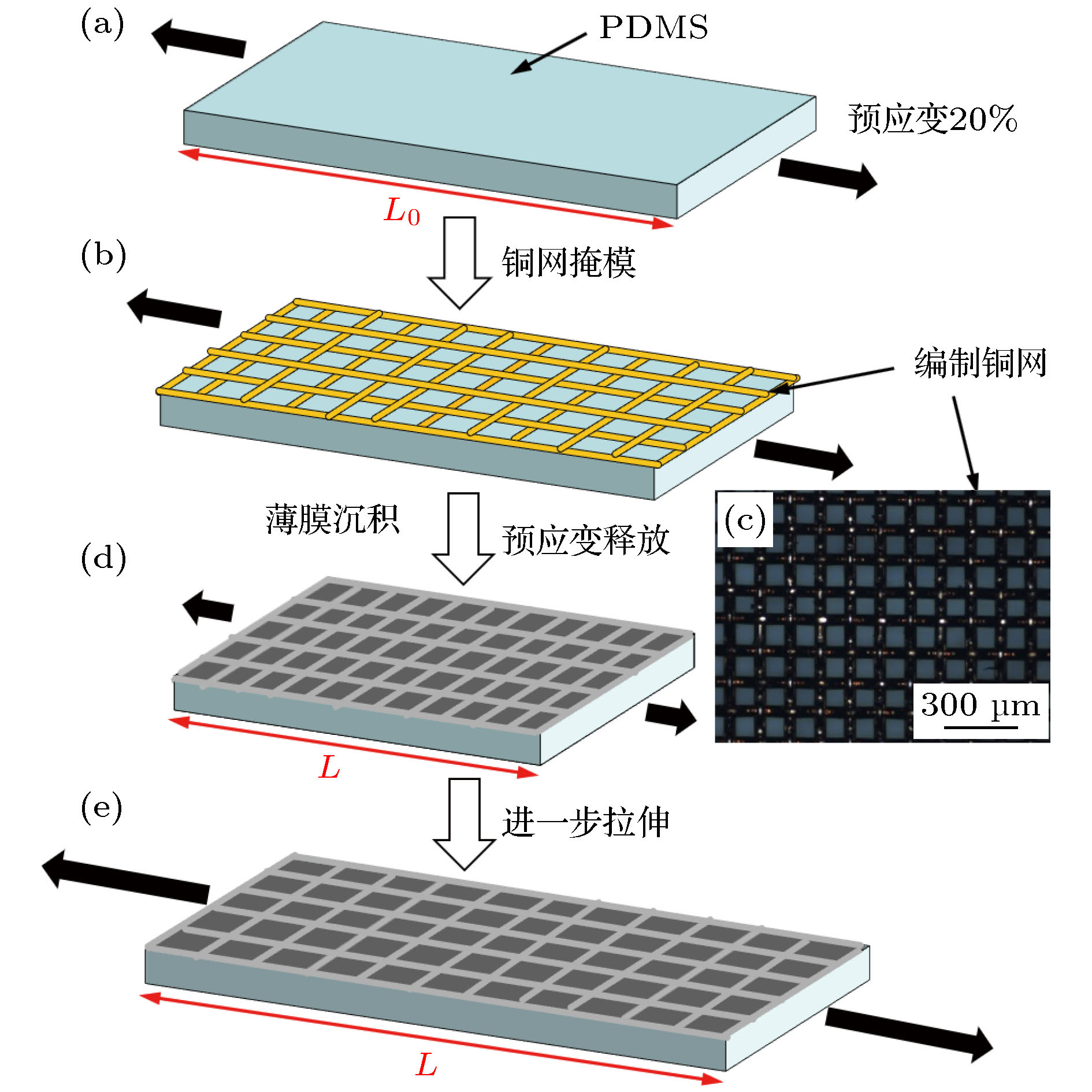
图 1 PDMS基底上周期性厚度梯度薄膜的制备流程及应变施加过程 (a) PDMS基底预拉伸至20%的预应变; (b)编织铜网覆盖到预拉伸的PDMS表面; (c)编织铜网的光学显微镜照片; (d)银薄膜沉积之后, 移除铜网, 并释放预应变至PDMS的原长; (e)进一步拉伸PDMS至任意长度L
Fig. 1. Schematic illustration of sample preparation and loading sequence of periodic thickness-gradient films on PDMS substrates: (a) The PDMS substrate was stretched to 20% prestrain; (b) a weaved copper grid was placed on the pre-stretched PDMS surface; (c) optical micrograph of the weaved copper grid; (d) after deposition of silver film, the copper grid was removed and the prestrain was released to the original length of PDMS; (e) the PDMS substrate was further stretched to a random length, namely L.
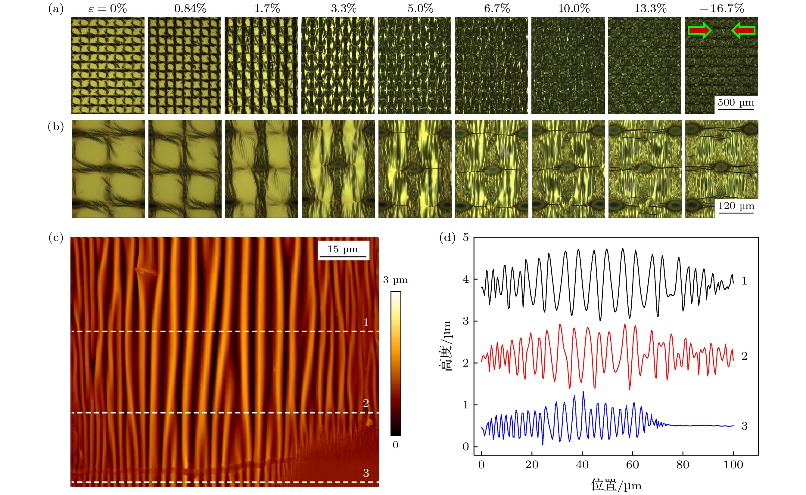
图 2 PDMS基底上周期性厚度梯度Ag薄膜受单轴压缩的形貌演化及结构特征 (a)光学显微镜放大50倍的图片, 尺寸均为1042 μm × 1390 μm, 箭头指向代表压缩方向; (b)光学显微镜放大200倍的图片, 尺寸均为261 μm × 348 μm; (c)单个网孔内薄膜表面形貌的原子力显微镜图片; (d)不同位置的剖面线结构
Fig. 2. Morphological evolutions and structural characteristics of periodic thickness-gradient Ag films on PDMS substrates under uniaxial compression: (a) Optical micrographs with 50× magnification. All the images have the size of 1042 μm × 1390 μm. The arrows represent the direction of compression. (b) Optical micrographs with 200× magnification. All the images have the size of 261 μm × 348 μm. (c) Atomic force microscopy (AFM) image of the film surface within a grid period. (d) Cross-sectional profiles of the film surface at different positions.
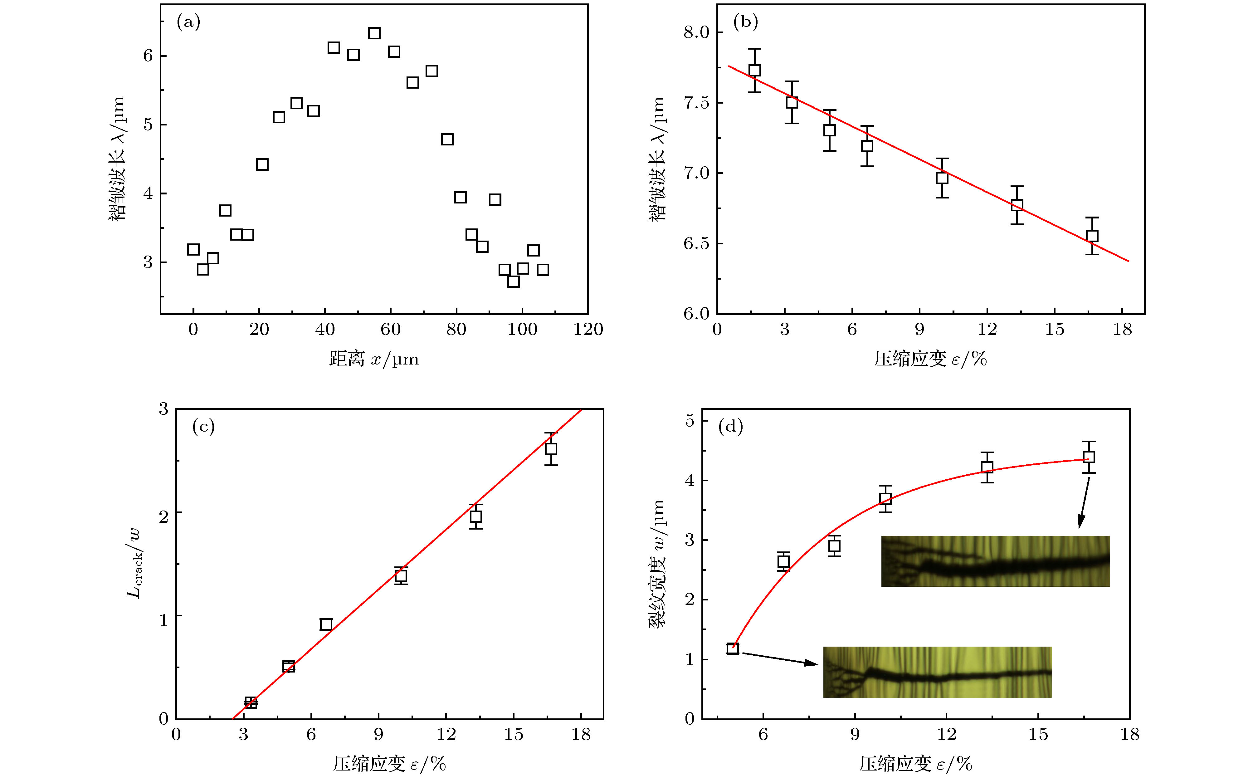
图 3 (a)一个周期内褶皱波长沿着中心线的演化规律; (b)中心区域褶皱的波长与机械压缩应变的关系, 实线为手风琴模型的理论结果; (c)归一化的裂纹长度(裂纹长度与网孔宽度之比)与机械应变的关系, 实线为实验数据的线性拟合; (d)裂纹宽度与机械应变的关系, 插图为不同应变下的裂纹形貌, 尺寸均为70 μm × 16 μm
Fig. 3. (a) Evolution of wrinkle wavelength along the center line within a grid period. (b) dependence of the wrinkle wavelength at the mesh center on the mechanical compressive strain. The solid line represents theoretical prediction of accordion model. (c) dependence of normalized crack length (the ratio of crack length to mesh width) on the mechanical strain. The solid line is a linear fit to the experimental data. (d) dependence of the crack width on the mechanical strain. The insets (both 70 μm × 16 μm) show the crack morphologies under different strains.
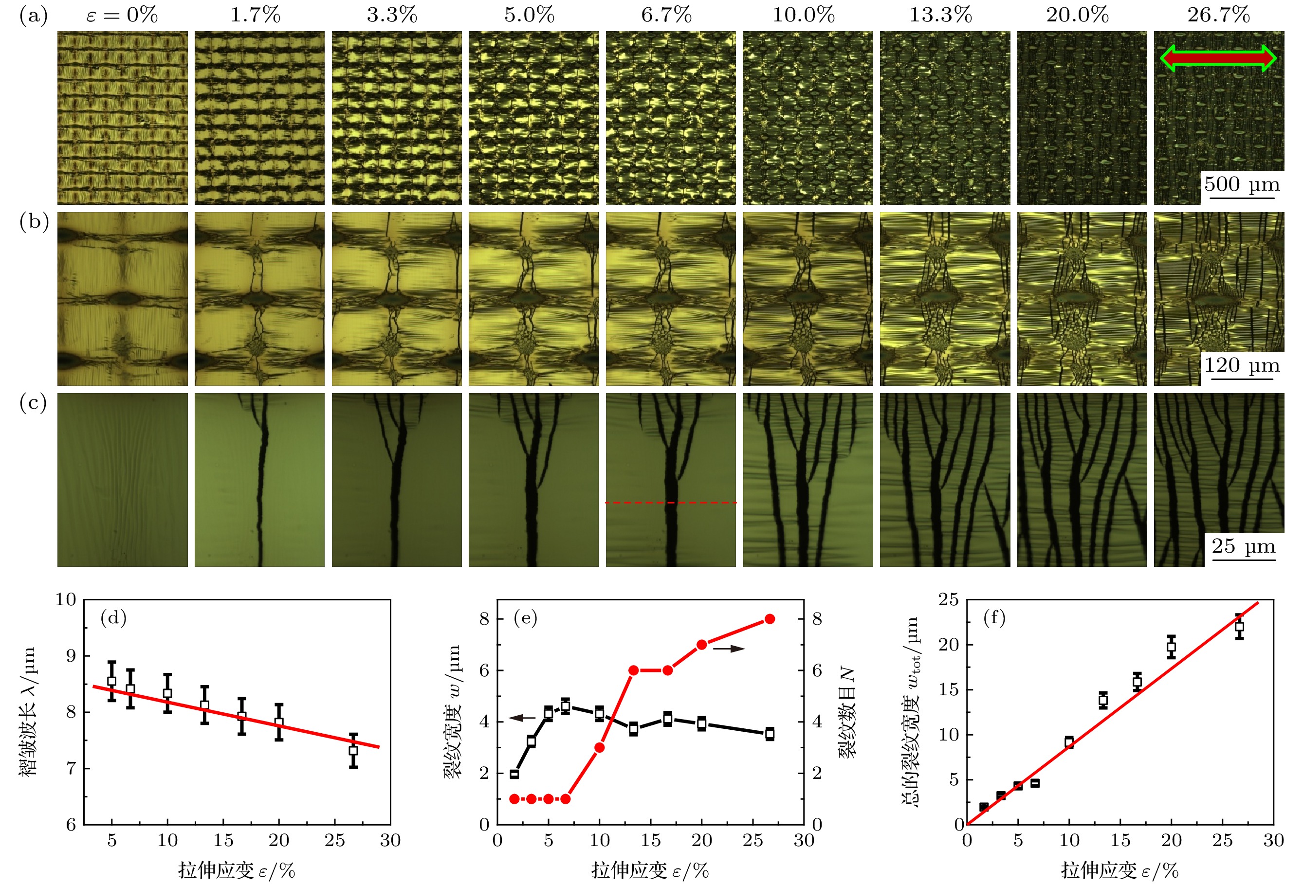
图 4 PDMS基底上周期性厚度梯度Ag薄膜受单轴拉伸的形貌演化及结构特征: (a)光学显微镜放大50倍的图片, 尺寸均为1042 μm × 1390 μm, 箭头指向代表拉伸方向; (b)光学显微镜放大200倍的图片, 尺寸均为261 μm × 348 μm; (c)光学显微镜放大500倍的图片, 尺寸均为104 μm × 139 μm; (d)中心区域的褶皱波长与机械拉伸应变的关系, 实线为手风琴模型的理论结果; (e)沿中心线的裂纹宽度和裂纹数目随应变的演化规律; (f)总的裂纹宽度与机械应变的关系, 实线为实验数据的线性拟合.
Fig. 4. Morphological evolutions and structural characteristics of periodic thickness-gradient Ag films on PDMS substrates under uniaxial tension: (a) Optical micrographs with 50× magnification. All the images have the size of 1042 μm × 1390 μm. The arrows represent the direction of tension. (b) Optical micrographs with 200× magnification. All the images have the size of 261 μm × 348 μm. (c) Optical micrographs with 500× magnification. All the images have the size of 104 μm × 139 μm. (d) Dependence of the wrinkle wavelength at the mesh center on the mechanical tensile strain. The solid line represents theoretical prediction of accordion model. (e) Evolutions of the crack width and crack number along the center line with the tensile strain. (f) Dependence of the total crack width on the tensile strain. The solid line is a linear fit to the experimental data.
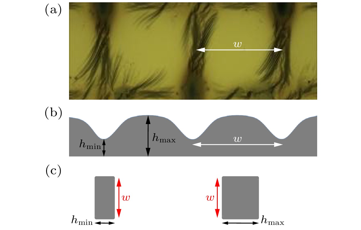
图 5 (a)周期性厚度梯度Ag薄膜的表面形貌,
$\varepsilon = 0$ ; (b)沿中心线薄膜厚度分布的示意图; (c)膜厚最小区域和最大区域的薄膜横截面示意图. 注意: 图中薄膜厚度h与网孔周期w并不按比例绘制, 膜厚被极大地放大了, 事实上膜厚在纳米量级(最大约90 nm), 而网孔周期在微米量级(约125 μm), 它们之间相差3个数量级Fig. 5. (a) Surface morphology of a periodic thickness-gradient Ag film when
$\varepsilon = 0$ ; (b) schematic diagram of the periodic thickness-gradient film along the center line. Note that the film thickness is greatly exaggerated. In fact, the grid period (w ~ 125 μm) is three orders of magnitude larger than the film thickness (hmax ~ 90 nm).图 6 (a)
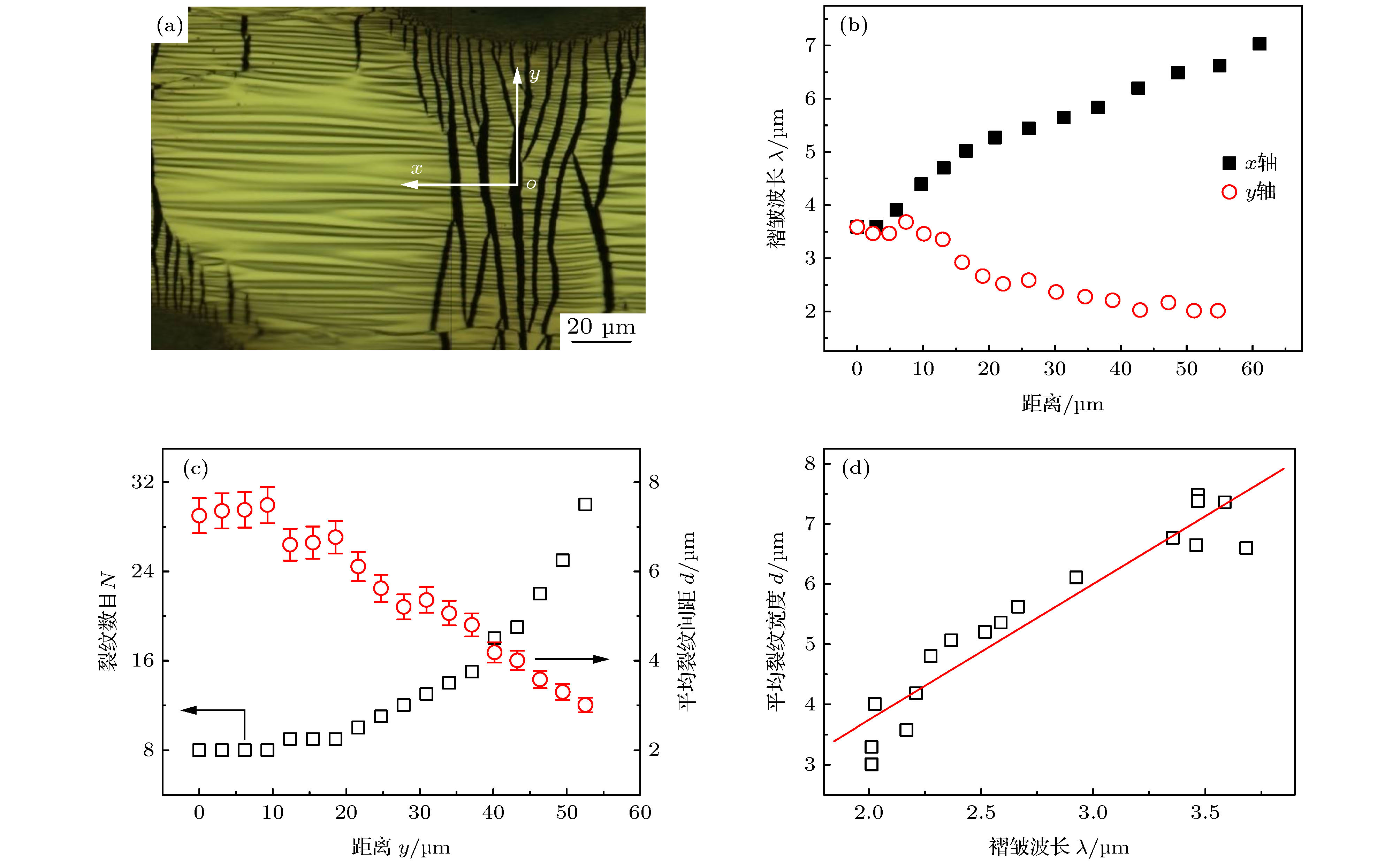
$\varepsilon = 20\% $ 时单个周期的典型结构特征; (b)在x和y方向上, 褶皱波长随距离的演化规律; (c)裂纹数目和裂纹平均间距随距离y的变化规律; (d)在y方向上, 裂纹平均间距和褶皱波长的依赖关系, 实线为实验数据的线性拟合Fig. 6. (a) Typical surface morphology of Ag film within a grid period under
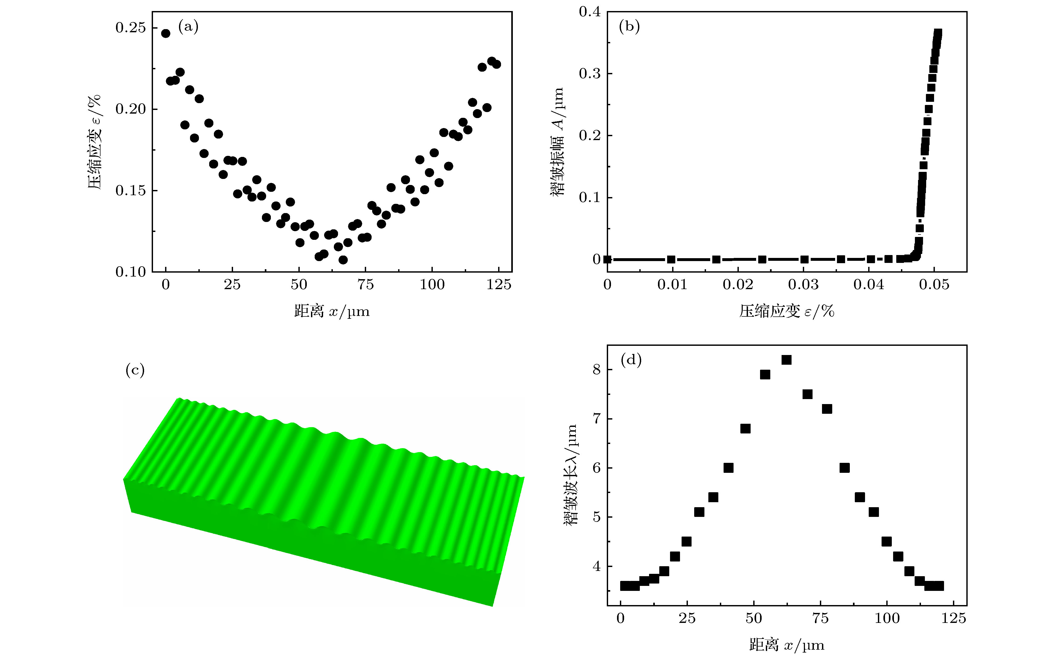
$\varepsilon = 20\% $ ; (b) evolutions of the wrinkle wavelength with the distance both in x and y directions; (c) evolutions of the crack number and average crack spacing with the distance y; (d) dependence of the average crack spacing on the wrinkle wavelength in the y direction and the solid line is a linear fit to the experimental data.图 8 有限元模拟结果 (a)一个周期内薄膜面内压应变的分布图; (b)褶皱幅值随薄膜面内压应变的演化规律; (c)一个周期内褶皱形貌的模拟图; (d)褶皱波长在一个周期的变化规律
Fig. 8. Finite element simulation results: (a) Distribution of the in-plane compressive strain within a period; (b) evolution of the wrinkle amplitude with the in-plane compressive strain; (c) simulated wrinkle morphology within a period; (d) distribution of the wrinkle wavelength within a period.
-
[1] Li B, Cao Y P, Feng X Q, Gao H J 2012 Soft Matter 8 5728
 Google Scholar
[2] 许宏, 苑争一, 黄彤飞, 王啸, 陈正先, 韦进, 张翔, 黄元 2020 69 026101
 Google Scholar
Xu H, Yuan Z Y, Huang T F, Wang X, Chen Z X, Wei J, Zhang X, Huang Y 2020 Acta Phys. Sin. 69 026101
 Google Scholar
[3] 倪勇, 刘佩琳, 马龙, 李世琛, 何陵辉 2018 固体力学学报 39 113
Ni Y, Liu P L, Ma L, Li S C, He L H 2018 Chin. J. Solid Mech. 39 113
[4] Lee W K, Odom T W 2019 ACS Nano 13 6170
 Google Scholar
[5] Ma L, He L, Ni Y 2020 J. Appl. Phys. 127 111101
 Google Scholar
[6] 冯雪, 陆炳卫, 吴坚, 林媛, 宋吉舟, 宋国锋, 黄永刚 2014 63 014201
 Google Scholar
Feng X, Lu B W, Wu J, Lin Y, Song J Z, Song G F, Huang Y G 2014 Acta Phys. Sin. 63 014201
 Google Scholar
[7] Kim H N, Ge D, Lee E, Yang S 2018 Adv. Mater. 30 1803847
 Google Scholar
[8] Gao N, Zhang X, Liao S, Jia H, Wang Y 2016 ACS Macro Lett. 5 823
 Google Scholar
[9] Lee W K, Jung W B, Rhee D, Hu J, Lucy Lee Y A, Jacobson C, Jung H T, Odom T W 2018 Adv. Mater. 30 1706657
 Google Scholar
[10] 王月桐, 商珞然, 赵远锦 2020 69 084701
 Google Scholar
Wang Y T, Shang L R, Zhao Y J 2020 Acta Phys. Sin. 69 084701
 Google Scholar
[11] Yu S, Liu X, Sun Y, Zhou H, Cai P 2019 Thin Solid Films 669 355
 Google Scholar
[12] Yin J, Yagüe J L, Eggenspieler D, Gleason K K, Boyce M C 2012 Adv. Mater. 24 5441
 Google Scholar
[13] Bowden N, Brittain S, Evans A G, Hutchinson J W, Whitesides G M 1998 Nature 393 146
 Google Scholar
[14] Wu D, Yin Y J, Xie H M, Shang Y F, Li C W, Wu L F, Dai X L 2014 Sci. China-Phys. Mech. Astron. 57 637
 Google Scholar
[15] Um D S, Lim S, Lee Y, Lee H, Kim H, Yen W C, Chueh Y L, Ko H 2014 ACS Nano 8 3080
 Google Scholar
[16] Wang D, Cheewaruangroj N, Li Y, McHale G, Jiang Y, Wood D, Biggins J S, Xu B B 2018 Adv. Funct. Mater. 28 1704228
 Google Scholar
[17] Chan E P, Crosby A J 2006 Soft Matter 2 324
 Google Scholar
[18] Ouchi T, Yang J, Suo Z, Hayward R C 2018 ACS Appl. Mater. Interfaces 10 23406
 Google Scholar
[19] Ding W, Yang Y, Zhao Y, Jiang S, Cao Y, Lu C 2013 Soft Matter 9 3720
 Google Scholar
[20] Gurmessa B J, Croll A B 2017 Soft Matter 13 1764
 Google Scholar
[21] Nogales A, Del Campo A, Ezquerra T A, Rodriguez-Hernandez J 2017 ACS Appl. Mater. Interfaces 9 20188
 Google Scholar
[22] Li B, Zeng C Q, Yin S F, Feng X Q 2019 Sci. China-Technol. Sci. 62 747
 Google Scholar
[23] Ni Y, Yang D, He L 2012 Phys. Rev. E 86 031604
[24] Yu S, Ni Y, He L, Ye Q L 2015 ACS Appl. Mater. Interfaces 7 5160
 Google Scholar
[25] Yu S, Ma L, Sun Y, Lu C, Zhou H, Ni Y 2019 Langmuir 35 7146
 Google Scholar
[26] Zhang Q, Tang Y, Hajfathalian M, Chen C, Turner K T, Dikin D A, Lin G, Yin J 2017 ACS Appl. Mater. Interfaces 9 44938
 Google Scholar
[27] Cerda E, Mahadevan L 2003 Phys. Rev. Lett. 90 074302
 Google Scholar
[28] Sun J Y, Xia S, Moon M W, Oh K H, Kim K S 2012 Proc. R. Soc. A 468 932
 Google Scholar
[29] Marthelot J, Roman B, Bico J, Teisseire J, Dalmas D, Melo F 2014 Phys. Rev. Lett. 113 085502
 Google Scholar
[30] Kappert E J, Pavlenko D, Malzbender J, Nijmeijer A, Benes N E, Tsai P A 2015 Soft Matter 11 882
 Google Scholar
[31] Volynskii A L, Bazhenov S, Lebedeva O V, Ozerin A N, Bakeev N F 1999 J. Appl. Polym. Sci. 72 1267
 Google Scholar
[32] Chen X, Hutchinson J W 2004 J. Appl. Mech. 71 597
 Google Scholar
[33] Jiang H, Khang D Y, Song J, Sun Y, Huang Y, Rogers J A 2007 Proc. Natl. Acad. Sci. U. S. A. 104 15607
 Google Scholar
[34] Huang Z Y, Hong W, Suo Z 2005 J. Mech. Phys. Solids 53 2101
 Google Scholar
[35] Pan K, Ni Y, He L, Huang R 2014 Int. J. Solids Struct. 51 3715
 Google Scholar
[36] Cao G, Chen X, Li C, Ji A, Cao Z 2008 Phys. Rev. Lett. 100 036102
 Google Scholar
[37] Zhang X, Mather P T, Bowick M J, Zhang T 2019 Soft Matter 15 5204
 Google Scholar
[38] Hibbett Karlsson Sorensen Inc. 2001 ABAQUS/Standard user's manual: version 6.2
[39] Riks E 1979 Int. J. Solids Struct. 15 529
 Google Scholar
计量
- 文章访问数: 9346
- PDF下载量: 204
- 被引次数: 0


 下载:
下载:
