


-
航行器在水中行驶时产生的摩擦阻力是影响其耗能和速度最主要的原因, 主动减阻技术对降低水下航行器航行过程中摩擦阻力, 提升航行器综合性能具有重要意义. 本文采用分子动力学方法研究了通入气体后Couette流在纳米通道内液体的流动特性和边界减阻特性, 分析了表面润湿性、剪切速度和气体通入量对边界滑移速度和减阻效果的影响规律. 研究结果表明, 当气体以离散气泡形式吸附于固体表面时, 气泡会阻碍近壁面液体流动及滑移减阻, 增强表面疏水性、提高剪切速度及增大气体通入量可促进气泡横向铺展, 减弱对液体流动的阻碍作用, 提升滑移效果; 提高表面疏水性、剪切速度和气体通入量均有利于离散气泡形成气膜; 气膜形成后, 剪切应力显著降低, 滑移速度随润湿性、剪切速度和气体通入量的变化呈现不同的变化规律. 研究结果为船舶和水下航行器中主动气膜减阻技术和表面结构设计提供理论依据.Friction resistance is the primary factor influencing the energy consumption and speed of underwater vehicles. Active air layer drag reduction is an active boundary layer control technique that reduces wall friction drag by injecting gas into the solid-liquid boundary layer. Compared with other drag reduction methods, which are often difficult to scale due to high costs and potential environmental concerns, this technology utilizes a simple auxiliary device. By employing inexpensive and environmentally friendly compressed air or combustion exhaust gases, it effectively lowers fluid resistance. Therefore, active drag reduction technology plays a crucial role in minimizing friction and enhancing overall performance. In this study, molecular dynamics simulations are used to construct a Couette flow shear model, with gas injected at the boundaries of a nanochannel. The flow characteristics and boundary drag reduction of Couette flow in a nanochannel is investigated in this work. The influence of gas injection on these characteristics is examined, along with the effects of surface wettability, shear velocity, and gas injection rate on boundary slip velocity and drag reduction. The results indicate that the gas adsorption on the solid surface in the form of discrete bubbles hinders liquid flowing and slipping near the wall, leading to the increase of drag. However, increasing surface hydrophobicity, shear rate, and gas injection rate facilitates the transverse spreading of bubbles, reduces flow obstruction, and enhances slip. Additionally, these factors promote the formation of a continuous gas layer from discrete bubbles, further improving drag reduction. Once the gas layer forms, shear stress decreases significantly, and slip velocity varies with surface wettability, shear velocity, and gas injection rate. These findings provide a theoretical foundation for developing the active gas layer drag reduction technology and optimizing the surface structures in ships and underwater vehicles.
-
Keywords:
- active drag reduction /
- boundary slip /
- Couette flow /
- molecular dynamic
[1] Sindagi S, Vijayakumar R 2021 Ships Offshore Struct. 16 968
 Google Scholar
[2] Fu Y F, Yuan C Q, Bai X Q 2017 Biosurf. Biotribol. 3 11
Google Scholar
[3] Ceccio S L 2010 Annu. Rev. Fluid Mech. 42 183
Google Scholar
[4] 康晓宣, 胡建新, 林昭武, 潘定一 2023 力学学报 55 1087
Google Scholar
Kang X X, Hu J X, Lin Z W, Pan D Y 2023 Chin. J. Theor. Appl. Mech. 55 1087
Google Scholar
[5] 李芳, 赵刚, 刘维新, 张殊, 毕红时 2015 64 034703
Google Scholar
Li F, Zhao G, Liu W X, Zhang S, Bi H S 2015 Acta Phys. Sin. 64 034703
Google Scholar
[6] 张晨远, 张智嘉, 丛巍巍, 魏浩, 张松松 2023 化学通报 86 863
Google Scholar
Zhang C Y, Zhang Z J, Cong W W, Wei H, Zhang S S 2023 Chemistry 86 863
Google Scholar
[7] Pakzad H, Liravi M, Moosavi A, Nouri B A, Najafkhani H 2020 Appl. Sur. Sci. 513 145754
Google Scholar
[8] Yue P P, Zhang M, Zhao T, Liu P, Peng F, Yang L Q 2024 Ind. Crop. Prod. 214 118523
Google Scholar
[9] Makiharju S A, Perlin M, Ceccio S L 2012 Int. J. Nav. Arch. Ocean 4 412
Google Scholar
[10] McCormick M E, Bhattacharyya R 1973 Naval Engineers Journal 85 11
Google Scholar
[11] Kumagai I, Takahashi Y, Murai Y 2015 Ocean Eng. 95 183
Google Scholar
[12] Gao Q D, Lu J S, Zhang G L, Zhang J W, Wu W F, Deng J J 2023 Ocean Eng. 272 113804
Google Scholar
[13] Zhao X J, Zong Z 2022 Ocean Eng. 251 111032
Google Scholar
[14] Tanaka T, Oishi Y, Park H J, Tasaka Y, Murai Y, Kawakita C 2023 Ocean Eng. 272 113807
Google Scholar
[15] Samuel A, Jia W D, Ou M X, Wang P, Gong C 2019 Appl. Eng. Agric. 35 795
Google Scholar
[16] Dabbour M, He R H, Mintah B, Ma H L 2019 J. Food Process Eng. 42 e13084
Google Scholar
[17] Jiang Y, Li H, Hua L, Zhang D M 2020 Biosyst. Eng. 193 216
Google Scholar
[18] 张鹏, 张彦如, 张福建, 刘珍, 张忠强 2024 73 154701
Google Scholar
Zhang P, Zhang Y R, Zhang F J, Liu Z, Zhang Z Q 2024 Acta Phys. Sin. 73 154701
Google Scholar
[19] 刘汉伦, 张忠强, 郝茂磊, 程广贵, 丁建宁 2018 气体物理 3 32
Google Scholar
Liu H L, Zhang Z Q, Hao M L, Cheng G G, Ding J N 2018 Phys. Gases 3 32
Google Scholar
[20] Killian B, Alizée D, Thierry C, Paul L, Laurent V, Jean-François M 2025 Comput. Phys. Commun. 307 109427
Google Scholar
[21] Weijs J H, Snoeijer J H, Lohse D 2012 Phys. Rev. Lett. 108 104501
Google Scholar
[22] Mustafa O, Sophia J, Ali B, Adam A W 2025 Int. Commun. Heat Mass 163 108658
Google Scholar
[23] Meng J Q, Wang J, Wang L J, Lyu C H, Lyu Y P, Nie B H 2024 Colloid. Surf. A 684 133126
Google Scholar
[24] Qiu H, Guo W L 2019 J. Phys. Chem. Lett. 10 6316.
Google Scholar
[25] Yang J H, Yuan Q Z, Zhao Y P 2019 Sci. China Phys. Mech. 62 124611
Google Scholar
[26] García-Magariño A, Lopez-Gavilan P, Sor S, Terroba F 2023 J. Mar. Sci. Eng. 11 1315
Google Scholar
[27] Kitagawa A, Denissenko P, Murai Y 2019 Exp. Therm. Fluid Sci. 104 141
Google Scholar
[28] Tang S, Zhu Y, Yuan S 2023 J. Bionic Eng. 20 2797
Google Scholar
[29] Hu H, Wang D, Ren F, Bao L, Priezjev N V, Wen J 2018 Int. J. Multiphase Flow 104 166
Google Scholar
[30] 吕鹏宇, 薛 亚辉, 段慧玲 2016 力学进展 46 179
Google Scholar
Lyu P Y, Xue Y H, Duan H L 2016 Adv. Mech. 46 179
Google Scholar
-
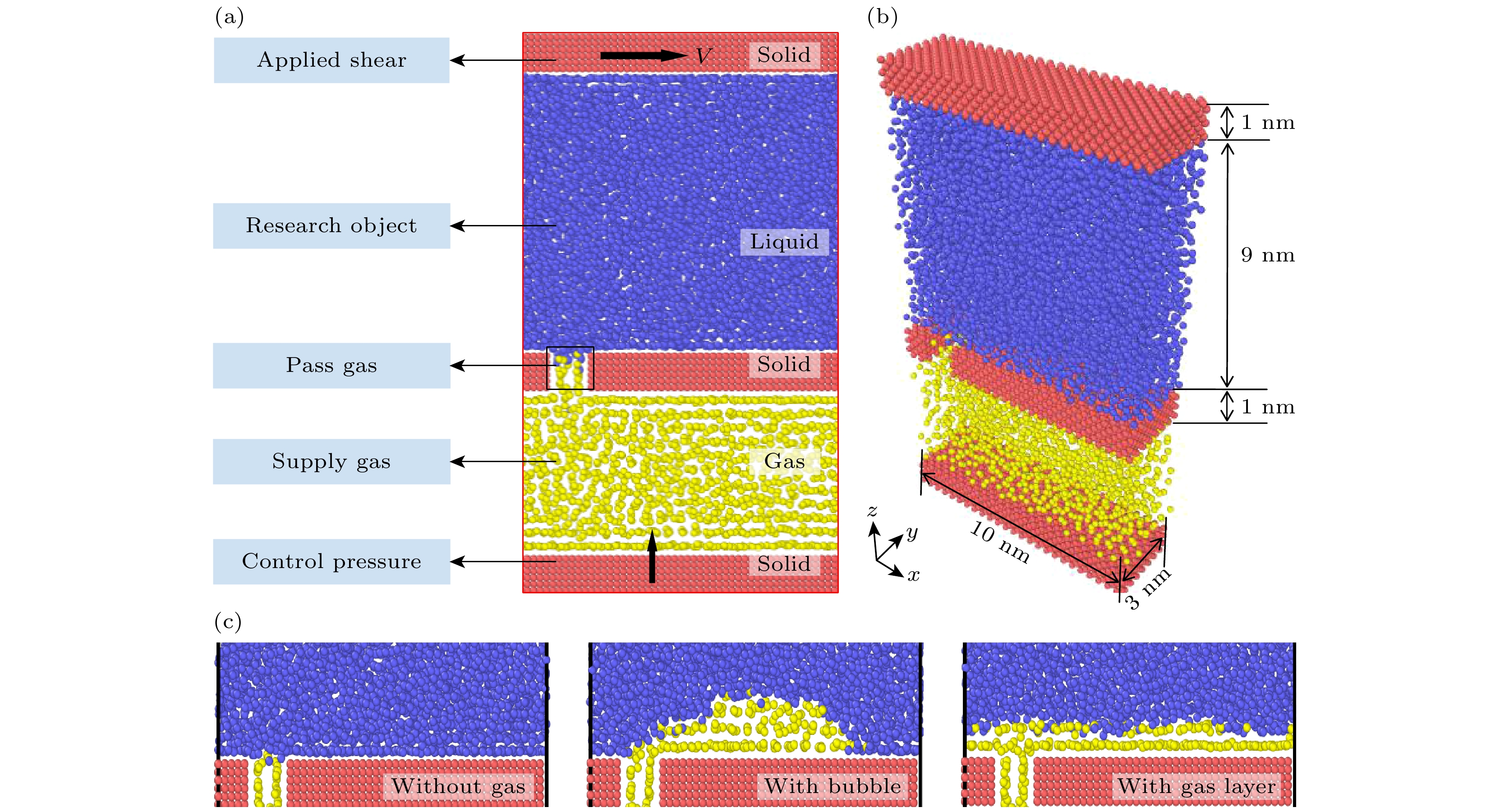
图 1 (a) Couette流剪切流动及通气系统模型示意图; (b) 模型主要尺寸; (c) 不同边界条件下气体形态图
Fig. 1. (a) Schematic diagram of Couette flow shear flow and ventilation system model; (b) main dimensions of the model; (c) gas morphology diagram under different boundary conditions.
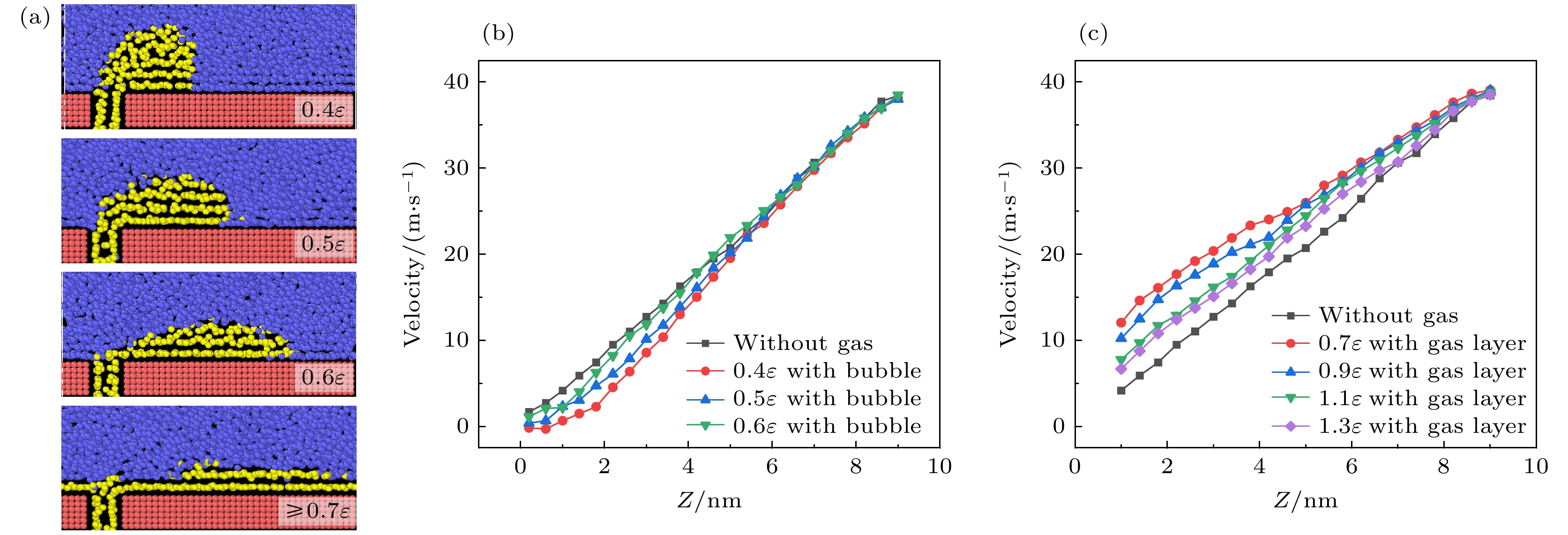
图 2 不同固-气耦合强度下, (a)气体形态图, 以及(b), (c)液体原子速度轮廓图, 其中(b)气泡, (c)气膜
Fig. 2. (a) Gas morphology and (b), (c) liquid atomic velocity profiles under different solid-gas interaction strengths, where (b) represents bubbles and (c) represents the gas layer.
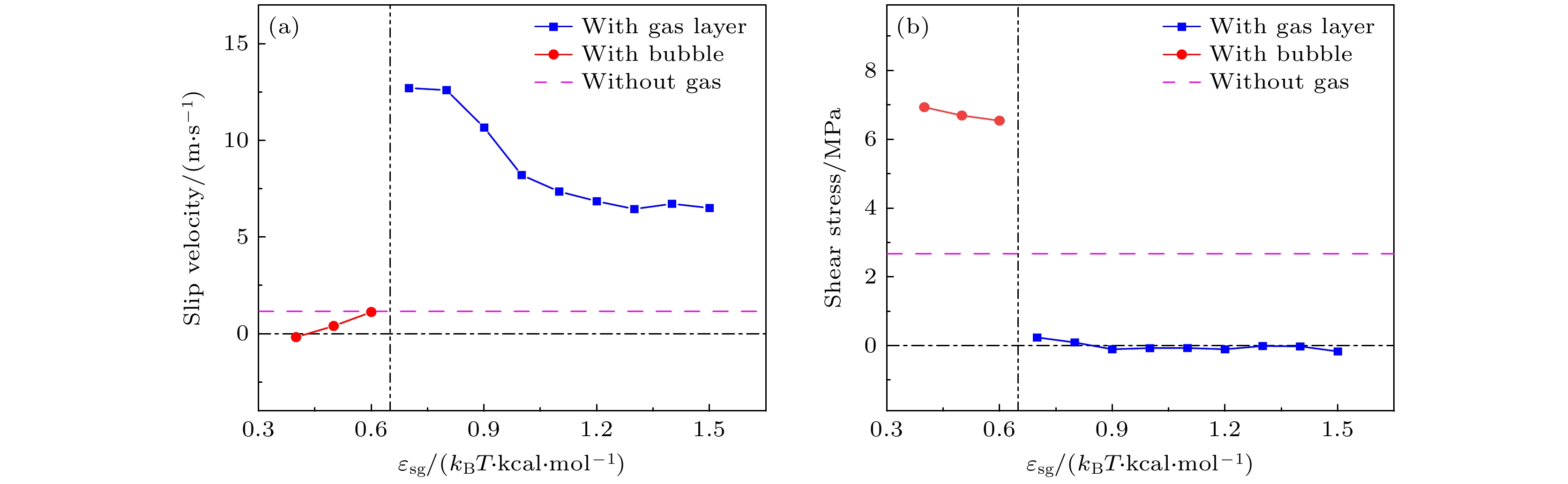
图 3 不同固-气耦合强度下, (a)边界滑移速度变化图和(b) 剪切应力变化图
Fig. 3. Boundary slip velocity (a) and shear stress (b) under different solid-gas interaction strengths.

图 4 不同固-气相互作用强度下的密度分布图 (a)无气体; (b)气泡; (c)气膜
Fig. 4. Density distribution under different solid-gas interaction strengths: (a) Without gas; (b) with bubble; (c) with gas layer.

图 5 不同剪切速度下, (a) 气体形态图, (b) 边界滑移速度和剪切应力图, 以及(c) 液体原子密度分布图
Fig. 5. (a) Gas morphology, (b) boundary slip velocity and shear stress, and (c) liquid atomic density distribution in the bubbles state under different shear velocities.
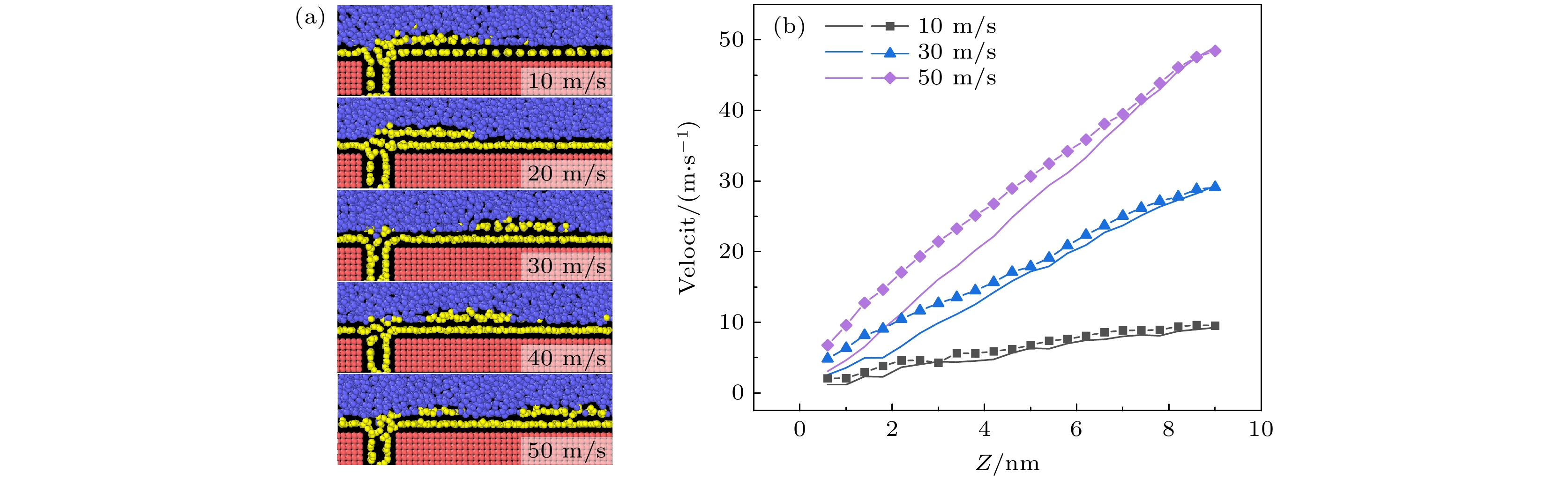
图 6 形成气膜后不同剪切速度下, (a) 气体形态图和(b) 液体原子速度轮廓图(其中半透明的线条为对照的无气体通入时的液体原子速度)
Fig. 6. (a) Gas morphology and (b) liquid atomic velocity profile under different shear velocities after the formation of gas layer. In panel (b), the translucent lines represent the liquid atomic velocity without gas injection for comparison.
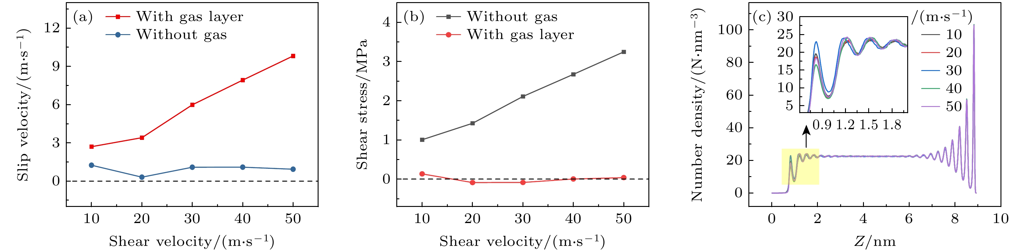
图 7 不同剪切速度下, (a) 边界滑移速度图、(b) 剪切应力图和(c) 液体原子速度轮廓图(气膜)
Fig. 7. (a) Boundary slip velocity, (b) shear stress, and (c) liquid atomic velocity profile in the gas layer state under different shear velocities.
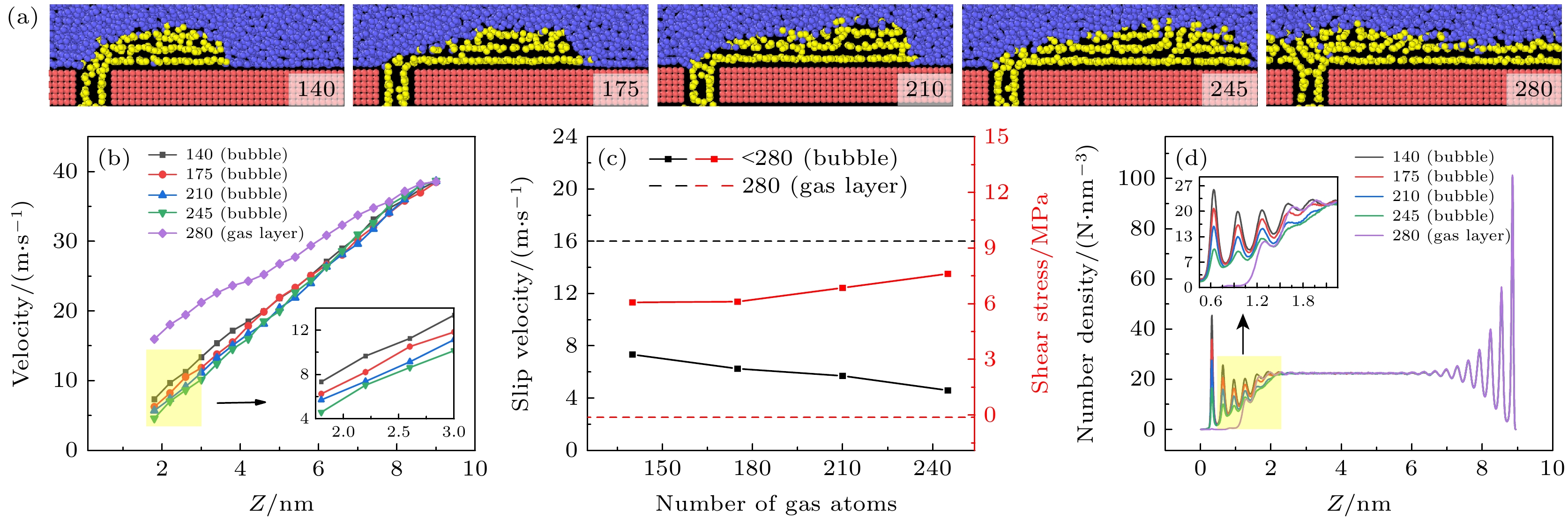
图 8 通入不同气体原子数量时, (a) 气体形态图、(b) 液体原子速度轮廓、(c) 边界滑移速度及剪切应力图和(d) 液体原子密度分布图
Fig. 8. (a) Gas morphology, (b) liquid atomic velocity profile, (c) boundary slip velocity and shear stress, and (d) liquid atomic density distribution in the bubbles state under different numbers of injected gas atoms.
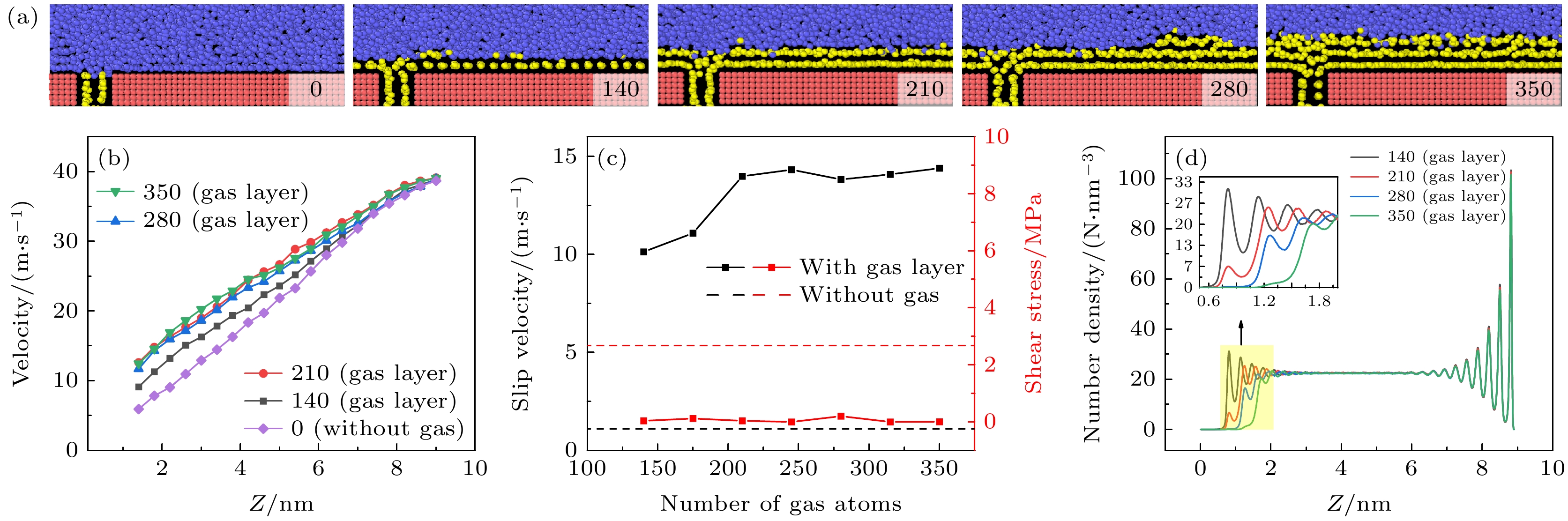
图 9 通入不同气体原子数量时, (a)气体形态图、(b)液体原子速度轮廓、(c)边界滑移速度及剪切应力图和(d) 液体原子密度分布图(气膜)
Fig. 9. (a) Gas morphology, (b) liquid atomic velocity profile, (c) boundary slip velocity and shear stress, and (d) liquid atomic density distribution in the gas layer state under different numbers of injected gas atoms.
表 1 三相相互作用势能参数
Table 1. Potential energy parameter of three-phase interaction.
两相类型 ε/(kBT )/(kcal·mol–1) σ/Å 固-固 1.2 3.4 液-液 1.2 3.4 气-气 0.4 5.0 固-液 0.7 3.4 固-气 1.0 4.2 液-气 0.4 4.488  下载: 导出CSV
-
[1] Sindagi S, Vijayakumar R 2021 Ships Offshore Struct. 16 968
Google Scholar
[2] Fu Y F, Yuan C Q, Bai X Q 2017 Biosurf. Biotribol. 3 11
Google Scholar
[3] Ceccio S L 2010 Annu. Rev. Fluid Mech. 42 183
Google Scholar
[4] 康晓宣, 胡建新, 林昭武, 潘定一 2023 力学学报 55 1087
Google Scholar
Kang X X, Hu J X, Lin Z W, Pan D Y 2023 Chin. J. Theor. Appl. Mech. 55 1087
Google Scholar
[5] 李芳, 赵刚, 刘维新, 张殊, 毕红时 2015 64 034703
Google Scholar
Li F, Zhao G, Liu W X, Zhang S, Bi H S 2015 Acta Phys. Sin. 64 034703
Google Scholar
[6] 张晨远, 张智嘉, 丛巍巍, 魏浩, 张松松 2023 化学通报 86 863
Google Scholar
Zhang C Y, Zhang Z J, Cong W W, Wei H, Zhang S S 2023 Chemistry 86 863
Google Scholar
[7] Pakzad H, Liravi M, Moosavi A, Nouri B A, Najafkhani H 2020 Appl. Sur. Sci. 513 145754
Google Scholar
[8] Yue P P, Zhang M, Zhao T, Liu P, Peng F, Yang L Q 2024 Ind. Crop. Prod. 214 118523
Google Scholar
[9] Makiharju S A, Perlin M, Ceccio S L 2012 Int. J. Nav. Arch. Ocean 4 412
Google Scholar
[10] McCormick M E, Bhattacharyya R 1973 Naval Engineers Journal 85 11
Google Scholar
[11] Kumagai I, Takahashi Y, Murai Y 2015 Ocean Eng. 95 183
Google Scholar
[12] Gao Q D, Lu J S, Zhang G L, Zhang J W, Wu W F, Deng J J 2023 Ocean Eng. 272 113804
Google Scholar
[13] Zhao X J, Zong Z 2022 Ocean Eng. 251 111032
Google Scholar
[14] Tanaka T, Oishi Y, Park H J, Tasaka Y, Murai Y, Kawakita C 2023 Ocean Eng. 272 113807
Google Scholar
[15] Samuel A, Jia W D, Ou M X, Wang P, Gong C 2019 Appl. Eng. Agric. 35 795
Google Scholar
[16] Dabbour M, He R H, Mintah B, Ma H L 2019 J. Food Process Eng. 42 e13084
Google Scholar
[17] Jiang Y, Li H, Hua L, Zhang D M 2020 Biosyst. Eng. 193 216
Google Scholar
[18] 张鹏, 张彦如, 张福建, 刘珍, 张忠强 2024 73 154701
Google Scholar
Zhang P, Zhang Y R, Zhang F J, Liu Z, Zhang Z Q 2024 Acta Phys. Sin. 73 154701
Google Scholar
[19] 刘汉伦, 张忠强, 郝茂磊, 程广贵, 丁建宁 2018 气体物理 3 32
Google Scholar
Liu H L, Zhang Z Q, Hao M L, Cheng G G, Ding J N 2018 Phys. Gases 3 32
Google Scholar
[20] Killian B, Alizée D, Thierry C, Paul L, Laurent V, Jean-François M 2025 Comput. Phys. Commun. 307 109427
Google Scholar
[21] Weijs J H, Snoeijer J H, Lohse D 2012 Phys. Rev. Lett. 108 104501
Google Scholar
[22] Mustafa O, Sophia J, Ali B, Adam A W 2025 Int. Commun. Heat Mass 163 108658
Google Scholar
[23] Meng J Q, Wang J, Wang L J, Lyu C H, Lyu Y P, Nie B H 2024 Colloid. Surf. A 684 133126
Google Scholar
[24] Qiu H, Guo W L 2019 J. Phys. Chem. Lett. 10 6316.
Google Scholar
[25] Yang J H, Yuan Q Z, Zhao Y P 2019 Sci. China Phys. Mech. 62 124611
Google Scholar
[26] García-Magariño A, Lopez-Gavilan P, Sor S, Terroba F 2023 J. Mar. Sci. Eng. 11 1315
Google Scholar
[27] Kitagawa A, Denissenko P, Murai Y 2019 Exp. Therm. Fluid Sci. 104 141
Google Scholar
[28] Tang S, Zhu Y, Yuan S 2023 J. Bionic Eng. 20 2797
Google Scholar
[29] Hu H, Wang D, Ren F, Bao L, Priezjev N V, Wen J 2018 Int. J. Multiphase Flow 104 166
Google Scholar
[30] 吕鹏宇, 薛 亚辉, 段慧玲 2016 力学进展 46 179
Google Scholar
Lyu P Y, Xue Y H, Duan H L 2016 Adv. Mech. 46 179
Google Scholar


 下载:
下载:


计量
- 文章访问数: 513
- PDF下载量: 17
- 被引次数: 0
