


-
A global model for deep oscillation magnetron sputtering (DOMS) discharge is established to investigate the plasma characteristics in the ionization region. Target voltage and current waveforms with micropulse on-time τon of 2–6 μs and charging voltage of 300–380 V are acquired and used as an input of the proposed model. The effects of micropulse on-time and charging voltage on the plasma are investigated. At τon = 2 μs, the DOMS plasma density oscillates with the discharge current waveform. The plasma is mainly composed of Ar+ ions though the ionization fraction of Ar is only 2%. The proportion of Cr+ ions is lower but has a relatively high ionization fraction of 12%, and Cr2+ ions are negligible. The peak plasma density increases from 1.34×10¹⁸ m–3 at τon = 2 μs to 2.64×10¹⁸ m–3 at τon = 3 μs and the metal ionization fraction increases to 20%. Further increasing the on-time leads the peak density and ionization fraction to slightly change. When the charging voltage increases from 300 V to 380 V at τon = 6 μs, the peak plasma density increases linearly from 2.67×10¹⁸ m–3 to 3.90×10¹⁸ m–3, and the metal ionization fraction increases from 21% to 28%. The gas rarefaction occurs in the ionization region for DOMS discharge. The gas density oscillates in the initial stage of macropulse, and 5–6 micropulses later it reaches dynamic equilibrium. The Ar density dynamics shows that the Ar consumption is mainly caused by electron impact ionization, followed by electron impact excitation, and the consumption rate caused by sputter wind is about 10% of the electron impact ionization. The typical metal self-sputtering phenomenon of high power impulse magnetron sputtering (HiPIMS) also appears in the DOMS discharge. The peak value of self-sputtering parameter increases linearly with the peak power density rising. This suggests that the peak power density is one of the important parameters to manipulate the metal self-sputtering process in the DOMS discharge. The peak value of self-sputtering parameter reaches up to 0.20, indicating that a certain degree of metal self-sputtering occurs. The plasma density and the ionization fraction of the depositing flux are improved, which relieves the shadowing effect during conventional magnetron sputtering as a result of low ionization degree of sputtered metal.
-
Keywords:
- deep oscillation magnetron sputtering /
- magnetron plasma /
- global model /
- Cr target /
- metal self-sputtering
[1] Kouznetsov V, Macák K, Schneider J M, Helmersson U, Petrov I 1999 Surf. Coat. Technol. 122 290
 Google Scholar
[2] Anders A 2011 Surf. Coat. Technol. 205 S1
Google Scholar
[3] Sarakinos K, Alami J, Konstantinidis S 2010 Surf. Coat. Technol. 204 1661
Google Scholar
[4] Greczynski G, Petrov I, Greene J E, Hultman L 2019 J. Vac. Sci. Technol. A 37 60801
Google Scholar
[5] Christie D J, Tomasel F, Sproul W D, Carter D C 2004 J. Vac. Sci. Technol. A 22 1415
Google Scholar
[6] Hajihoseini H, Čada M, Hubička Z, Ünaldi S, Raadu M A, Brenning N, Gudmundsson J T, Lundin D 2019 Plasma 2 201
Google Scholar
[7] Lin J L, Wang B, Sproul W D, Ou Y X, Dahan I 2013 J. Phys. D: Appl. Phys. 46 84008
Google Scholar
[8] 王浩琦, 欧伊翔, 华青松, 邱马顺, 帅麒麟, 付薇 2022 北京师范大学学报(自然科学版) 58 775
Google Scholar
Wang H Q, Ou Y X, Hua Q S, Qiu M S, Shuai Q L, Fu W 2022 J. Beijing Normal Univ. (Nat. Sci.) 58 775
Google Scholar
[9] Sanekata M, Nakagomi Y, Hirayama M, Nishida H, Nishimiya N, Tona M, Yamamoto H, Tsukamoto K, Fuke K, Ohshimo K, Koyasu K, Misaizu F 2022 J. Appl. Phys. 131 243301
Google Scholar
[10] Yokoyama E, Sanekata M, Nishimiya N, Tona M, Yamamoto H, Tsukamoto K, Fuke K, Ohshimo K, Misaizu F 2023 Jpn. J. Appl. Phys. 62 L1008
Google Scholar
[11] 欧伊翔, 王浩琦, 庞盼, 罗军, 陈琳, 廖斌, 雷明凯, 欧阳晓平 2020 稀有金属材料与工程 49 2476
Ou Y X, Wang H Q, Pang P, Luo J, Chen L, Liao B, Lei M K, Ouyang X P 2020 Rare Metal Mat. Eng. 49 2476
[12] Oliveira J C, Fe Rnandes F, Fe Rreira F, Cavaleiro A 2015 Surf. Coat. Technol. 264 140
Google Scholar
[13] Ferreira F, Cavaleiro A, Oliveira J 2021 J. Mater. Eng. Perform. 30 3912
Google Scholar
[14] Belosludtsev A, Vlček J, Houška J, Haviar S, Čerstvý R 2020 Surf. Coat. Technol. 392 125716
Google Scholar
[15] Gao J Y, Ferreira F, Lei M K 2024 J. Appl. Phys. 135 33301
Google Scholar
[16] Gudmundsson J T, Fischer J, Hinriksson B P, Rudolph M, Lundin D 2022 Surf. Coat. Technol. 442 128189
Google Scholar
[17] Ziegler J F, Ziegler M D, Biersack J P 2010 Nucl. Instrum. Methods Phys. Res. B 268 1818
Google Scholar
[18] Gudmundsson J T 2020 Plasma Sources Sci. Technol. 29 113001
Google Scholar
[19] Vlček J, Kudláček P, Burcalová K, Musil J 2007 Europhys. Lett. 77 45002
Google Scholar
[20] Huo C, Raadu M A, Lundin D, Gudmundsson J T, Anders A, Brenning N 2012 Plasma Sources Sci. Technol. 21 45004
Google Scholar
[21] Anders A, Čapek J, Hála M, Martinu L 2012 J. Phys. D: Appl. Phys. 45 12003
Google Scholar
[22] Oliveira J C, Ferreira F, Anders A, Cavaleiro A 2018 Appl. Surf. Sci. 433 934
Google Scholar
-

图 1 充电电压300 V、微脉冲开启时间2 μs时, DOMS靶电压和电流波形
Figure 1. Typical target voltage and current waveforms of a DOMS discharge with τon = 2 μs and DCint = 300 V.
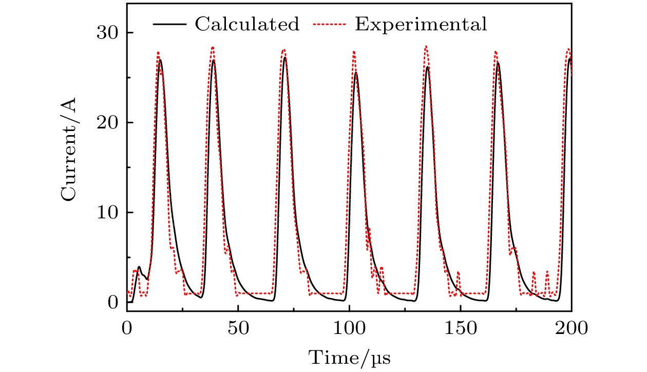
图 2 τon = 2 μs实验采集和模拟计算得到的DOMS放电靶电流
Figure 2. Experimental and calculated current waveforms at τon = 2 μs.

图 3 DOMS等离子体带电粒子密度随时间变化 (a) τon = 2 μs; (b) τon = 6 μs
Figure 3. Temporal evolution of charged particle densities in DOMS plasmas: (a) τon = 2 μs; (b) τon = 6 μs.
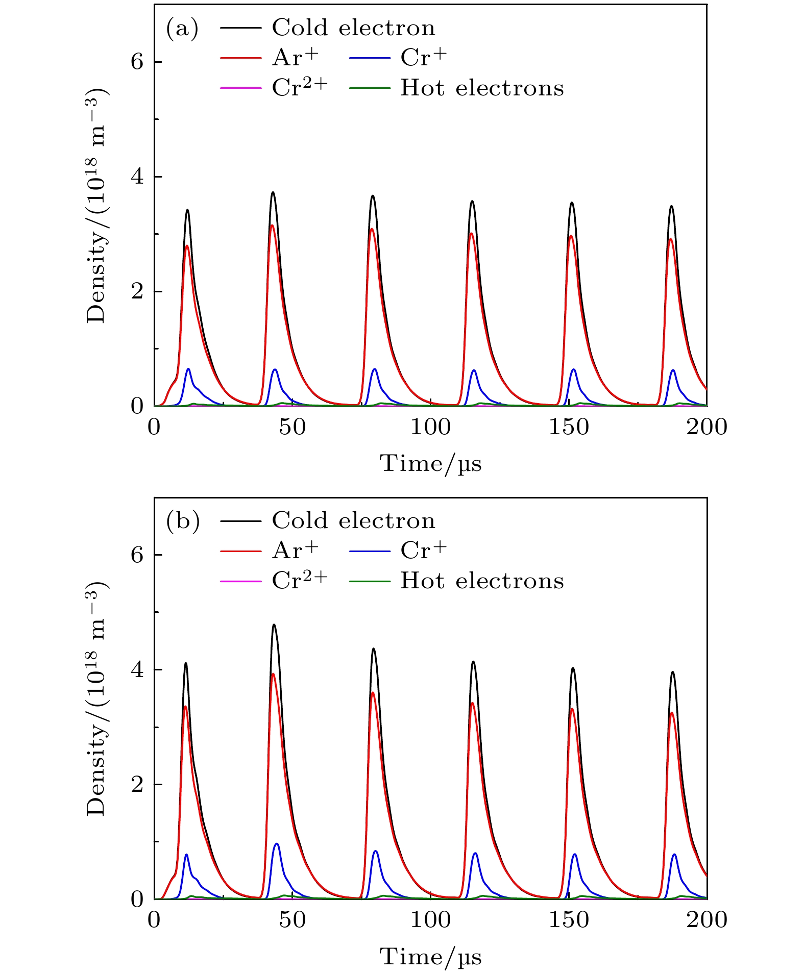
图 4 DOMS等离子体带电粒子密度随时间变化 (a) DCint = 340 V; (b) DCint = 380 V
Figure 4. Temporal evolution of charged particle densities in DOMS plasmas: (a) DCint = 340 V; (b) DCint = 380 V.

图 5 主要带电粒子峰值密度随不同参数变化 (a)微脉冲开启时间; (b)充电电压
Figure 5. Peak densities of charged particle densities as functions of the different parameters: (a) Micropulse on-time; (b) charging voltage.
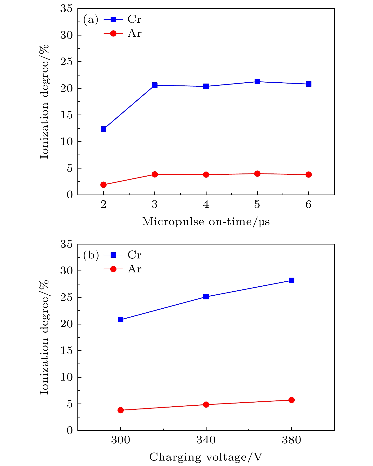
图 6 Cr和Ar峰值离化率随不同参数变化 (a) 微脉冲开启时间; (b)充电电压
Figure 6. Peak ionization degrees of Cr and Ar as functions of: (a) Micropulse on-time; (b) charging voltage.
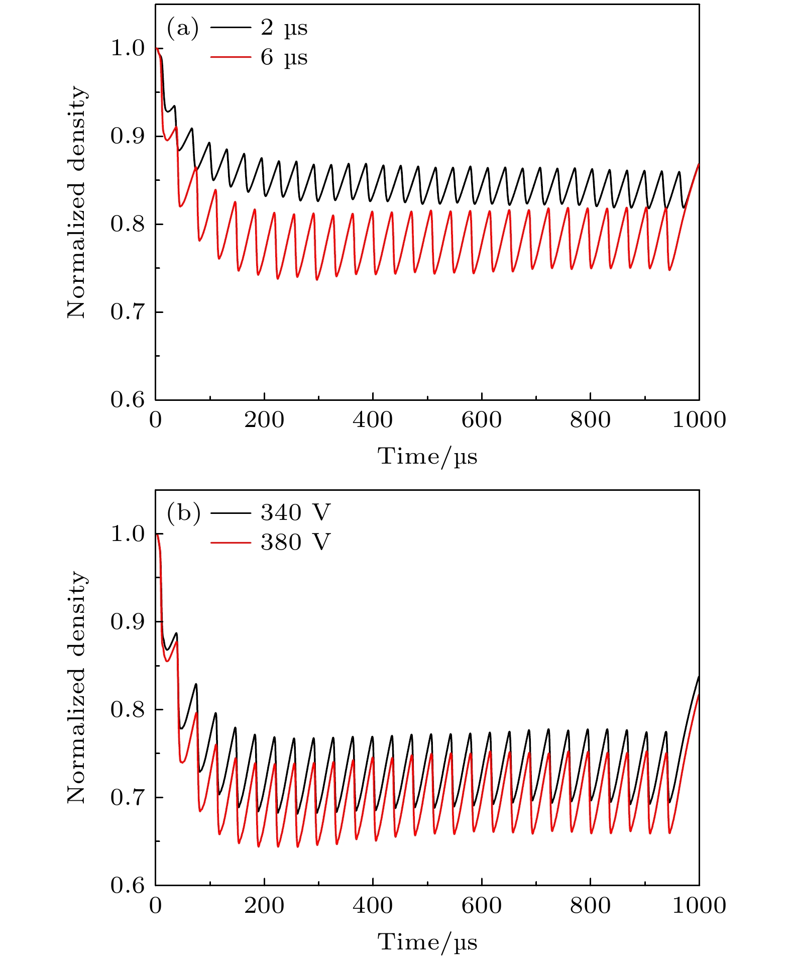
图 7 离化区工作气体归一化密度随时间变化 (a) τon为2 μs和6 μs; (b) DCint为340 V和380 V
Figure 7. Temporal evolution of normalized density of working gas in the ionization region: (a) τon = 2 and 6 μs; (b) DCint = 340 and 380 V.

图 8 充电电压300 V, Ar原子反应动力学 (a) τon = 2 μs; (b) τon = 6 μs
Figure 8. Dynamics of Ar atoms at DCint = 300 V: (a) τon = 2 μs; (b) τon = 6 μs.
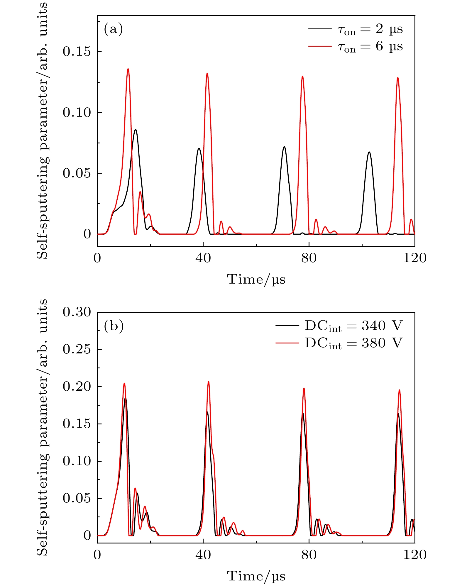
图 9 金属自溅射参数随时间变化 (a) τon为2和6 μs; (b) DCint为340和380 V
Figure 9. Temporal evolution of metal self-sputtering parameter: (a) τon = 2 and 6 μs; (b) DCint = 340 and 380 V.

图 10 峰值金属自溅射参数随不同参数变化 (a)微脉冲开启时间; (b)充电电压; (c)峰值功率密度
Figure 10. Peak self-sputtering parameter as function of different parameters: (a) Micropulse on-time; (b) charging voltage; (c) peak power density.
表 1 不同微脉冲开启时间DOMS放电参数
Table 1. Discharge parameters of DOMS using different micropulse on-time.
充电
电压/V微脉冲开启
时间τon/μs峰值
电压/V峰值
电流/A峰值
功率/kW300 2 635.8 27.5 14.4 300 3 729.0 50.6 29.8 300 4 714.4 49.4 29.2 300 5 726.0 51.5 31.0 300 6 731.6 51.5 30.8 340 6 810.6 63.8 42.2 380 6 870.7 73.5 48.7  DownLoad: CSV
表 2 DOMS溅射Cr靶主要等离子体反应
Table 2. Reactions considered in DOMS plasma using a Cr target.
反应 阈值/eV 速率系数/(m3·s–1) e + Ar → Ar+ + 2e 15.76 $2.3\times 10^{-14}T_{\rm e}^{0.59} \exp(-17.44/T_{\rm e}) $ e + Ar → Arm + e 11.56 $2.5\times 10^{-15}T_{\rm e}^{0.74}\exp(- 11.56/T_{\rm e}) $ e + Arm → Ar+ + 2e 4.20 $6.8\times 10^{-15}T_{\rm e}^{0.67} \exp(-4.2/T_{\rm e}) $ e + Cr → Cr+ + 2e 6.76 $4.12\times 10^{-13}T_{\rm e}^{ -0.151}\exp(- 10.71/T_{\rm e})$ e + Cr+ → Cr2+ + 2e 16.49 $5.27\times 10^{-14}T_{\rm e}^{ 0.087}\exp(- 22.05/T_{\rm e})$ Ar+ + Cr → Ar + Cr+ — $1\times10^{-15} $ Arm + Cr → Ar + Cr+ + e — $3.3\times10^{-16} $
DownLoad: CSV
-
[1] Kouznetsov V, Macák K, Schneider J M, Helmersson U, Petrov I 1999 Surf. Coat. Technol. 122 290
Google Scholar
[2] Anders A 2011 Surf. Coat. Technol. 205 S1
Google Scholar
[3] Sarakinos K, Alami J, Konstantinidis S 2010 Surf. Coat. Technol. 204 1661
Google Scholar
[4] Greczynski G, Petrov I, Greene J E, Hultman L 2019 J. Vac. Sci. Technol. A 37 60801
Google Scholar
[5] Christie D J, Tomasel F, Sproul W D, Carter D C 2004 J. Vac. Sci. Technol. A 22 1415
Google Scholar
[6] Hajihoseini H, Čada M, Hubička Z, Ünaldi S, Raadu M A, Brenning N, Gudmundsson J T, Lundin D 2019 Plasma 2 201
Google Scholar
[7] Lin J L, Wang B, Sproul W D, Ou Y X, Dahan I 2013 J. Phys. D: Appl. Phys. 46 84008
Google Scholar
[8] 王浩琦, 欧伊翔, 华青松, 邱马顺, 帅麒麟, 付薇 2022 北京师范大学学报(自然科学版) 58 775
Google Scholar
Wang H Q, Ou Y X, Hua Q S, Qiu M S, Shuai Q L, Fu W 2022 J. Beijing Normal Univ. (Nat. Sci.) 58 775
Google Scholar
[9] Sanekata M, Nakagomi Y, Hirayama M, Nishida H, Nishimiya N, Tona M, Yamamoto H, Tsukamoto K, Fuke K, Ohshimo K, Koyasu K, Misaizu F 2022 J. Appl. Phys. 131 243301
Google Scholar
[10] Yokoyama E, Sanekata M, Nishimiya N, Tona M, Yamamoto H, Tsukamoto K, Fuke K, Ohshimo K, Misaizu F 2023 Jpn. J. Appl. Phys. 62 L1008
Google Scholar
[11] 欧伊翔, 王浩琦, 庞盼, 罗军, 陈琳, 廖斌, 雷明凯, 欧阳晓平 2020 稀有金属材料与工程 49 2476
Ou Y X, Wang H Q, Pang P, Luo J, Chen L, Liao B, Lei M K, Ouyang X P 2020 Rare Metal Mat. Eng. 49 2476
[12] Oliveira J C, Fe Rnandes F, Fe Rreira F, Cavaleiro A 2015 Surf. Coat. Technol. 264 140
Google Scholar
[13] Ferreira F, Cavaleiro A, Oliveira J 2021 J. Mater. Eng. Perform. 30 3912
Google Scholar
[14] Belosludtsev A, Vlček J, Houška J, Haviar S, Čerstvý R 2020 Surf. Coat. Technol. 392 125716
Google Scholar
[15] Gao J Y, Ferreira F, Lei M K 2024 J. Appl. Phys. 135 33301
Google Scholar
[16] Gudmundsson J T, Fischer J, Hinriksson B P, Rudolph M, Lundin D 2022 Surf. Coat. Technol. 442 128189
Google Scholar
[17] Ziegler J F, Ziegler M D, Biersack J P 2010 Nucl. Instrum. Methods Phys. Res. B 268 1818
Google Scholar
[18] Gudmundsson J T 2020 Plasma Sources Sci. Technol. 29 113001
Google Scholar
[19] Vlček J, Kudláček P, Burcalová K, Musil J 2007 Europhys. Lett. 77 45002
Google Scholar
[20] Huo C, Raadu M A, Lundin D, Gudmundsson J T, Anders A, Brenning N 2012 Plasma Sources Sci. Technol. 21 45004
Google Scholar
[21] Anders A, Čapek J, Hála M, Martinu L 2012 J. Phys. D: Appl. Phys. 45 12003
Google Scholar
[22] Oliveira J C, Ferreira F, Anders A, Cavaleiro A 2018 Appl. Surf. Sci. 433 934
Google Scholar


 DownLoad:


Catalog
Metrics
- Abstract views: 4728
- PDF Downloads: 97
- Cited By: 0
