


-
Radiation power of an electromagnetic wave plays a decisive role in its transmission distance. Traditionally, the radiation power can be improved by expanding the radiation aperture size of the antenna array or increasing input power of the unit cell. However, the radiation aperture size is always restricted by assembly space. The input power improvement of the unit cell is always limited by the signal source. It is difficult to improve radiation power on a finite radiation aperture. However, the radiation power on a finite radiation aperture is related closely to the number of antenna elements and the radiation efficiency of the antenna array. It is useful to arrange more elements and improve radiation efficiency of the antenna array to improve the radiation power on a finite radiation aperture. Wideband wide-angle scanning phased array is able to make full use of a finite radiation aperture. The wide-angle scanning properties make it possible for the radiated power to cover a wide area. In this paper, a compact wideband wide-angle scanning tightly coupled dipole array (TCDA) is proposed. A high permittivity substrate and compact wideband balun are used for miniaturizing the antenna array. The period of the unit cell is only 0.144λhigh × 0.144λhigh (λhigh is the wavelength at the highest operation frequency in free space). Parameters of the balun are optimized to improve impedance matching between the balun and the antenna array. Two bilateral frequency selective surfaces (FSSs) are used to replace traditional dielectric superstrate to improve the impedance matching between the antenna array and free space. A low-loss dielectric substrate is used to reduce dielectric loss of the antenna array. In these ways, the radiation efficiency is greatly improved. The simulation results show that the proposed antenna array operates at 1.7–5.4 GHz (3.2:1) while scanning up to 65° in the E plane, 45° in the H plane and 60° in the D plane with following a rigorous impedance matching criterion (active VSWR < 2). A 16 × 16 prototype array is fabricated and measured. Good agreement is achieved between the simulation results and the measurement results. Compared with the designs in the literature, the proposed antenna array has an excellent performance in radiation power on a finite radiation aperture.
-
Keywords:
- radiated power /
- radiation aperture /
- phased array antennas /
- wideband wide-angle scanning
[1] Gold S H, Nusinovich G S 1997 Rev. Sci. Instrum. 68 3945
 Google Scholar
[2] Chen Y, Zhang Y P 2005 IEEE Antennas Wirel. Propag. Lett. 53 3089
Google Scholar
[3] Choe H, Lim S 2014 IEEE Trans. Antennas Propag. 62 5497
Google Scholar
[4] Li J F, Chu Q X, Huang T W 2012 IEEE Trans. Antennas Propag. 60 482
Google Scholar
[5] 陈昭福, 黄华, 常安碧, 许州, 何琥, 雷禄容, 胡进光, 袁欢, 刘振帮 2014 63 238402
Google Scholar
Chen Z F, Huang H, Chang A B, Xu Z, He H, Lei L R, Hu J J, Yuan H, Liu Z B 2014 Acta Phys. Sin. 63 238402
Google Scholar
[6] Munk B A 2003 Finite Antenna Arrays and FSS (USA: Wiley-IEEE Press) pp181−213
[7] Yetisir E, Ghalichechian N, Volakis J L 2016 IEEE Trans. Antennas Propag. 64 4256
Google Scholar
[8] Hu C H, Wang B Z, Gao G F, Wang R, Xiao S Q, Ding X 2020 IEEE Antennas Wirel. Propag. Lett. 20 63
[9] Zhang Y H, Yang S W, Xiao S W, Chen Y K, Qu S W, Hu J 2019 IEEE Antennas Wirel. Propag. Lett. 18 378
Google Scholar
[10] Lim T B, Zhu L 2008 Proceedings of the IEEE MTT-S International Microwave Workshop Series on Art Miniaturizing RF Microwave and Passive Components Chengdu, China, December 14−15, 2008 p153
[11] Zhu L, Bu H, Wu K 2000 IEEE MTT-S International Microwave Symposium Digest Boston, USA, June 11−16, 2000 p315
[12] Magill E G, Wheeler H A 1966 IEEE Trans. Antennas Propag. 14 49
Google Scholar
[13] Smith D R, Schultz S 2002 Phys. Rev. B 65 195104
Google Scholar
[14] Hood A Z, Karacolak T, Topsakal E 2008 IEEE Antennas Wirel. Propag. Lett. 7 656
Google Scholar
[15] Cavallo D, Syed W H, Neto A 2017 IEEE Trans. Antennas Propag. 65 1788
Google Scholar
[16] Hu C H, Wang B Z, Wang R, Xiao S Q, Ding X 2020 IEEE Trans. Antennas Propag. 68 2788
Google Scholar
[17] Moulder W F, Sertel K, Volakis J L 2013 IEEE Trans. Antennas Propag. 61 5802
Google Scholar
[18] Bah A O, Qin P Y, Ziolkowski RW, Guo Y J, Bird T S 2019 IEEE Trans. Antennas Propag. 67 2332
Google Scholar
[19] Jiang Z G, Xiao S Q, Yao Z X, Wang B Z 2020 IEEE Trans. Antennas Propag. 68 7348
Google Scholar
[20] Syed W H, Cavallo D, Shivamurthy H T, Neto A 2015 IEEE Trans. Antennas Propag. 64 543
[21] Xia R L, Qu S W, Yang S W, Chen Y K 2018 IEEE Trans. Antennas Propag. 66 1767
Google Scholar
-

图 1 天线单元结构 (a) 前视图 (红色馈线下方的地板被移除); (b) 后视图
Figure 1. Unit Cell of the TCDA: (a) Front view of the unit cell (the ground of the red parts is etched); (b) back view of the unit cell.
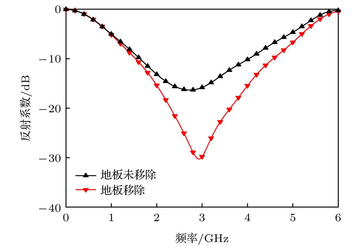
图 2 红色馈线下方地板未移除和地板移除时巴伦的反射系数
Figure 2. Reflection coefficients of the balun with and without the etched ground of the red feeding parts.

图 3 无限大阵列有加载和无加载匹配层在H面45°扫描时, 天线单元有源驻波比
Figure 3. Active VSWRs of the unit cell at 45° scanning in the H plane in infinite array simulation with and without frequency selective surfaces.

图 4 无限大阵列交叉极化水平 (a) 在不同面不同角度扫描时的交叉极化比; (b) 在3 GHz边射时, 天线口径面电场分布
Figure 4. Cross polarization level in infinite array simulation: (a) Cross polarization ratio at different angles scanning in different planes; (b) electric field on radiation aperture at 3 GHz.

图 5 无限大阵列在边射、E面65°、D面60°和H面45°扫描时, 天线阵的辐射效率
Figure 5. Radiation efficiency of the proposed antenna array at broadside, 65° scanning in the E plane, 45° scanning in the H plane and 60° scanning in the D plane.
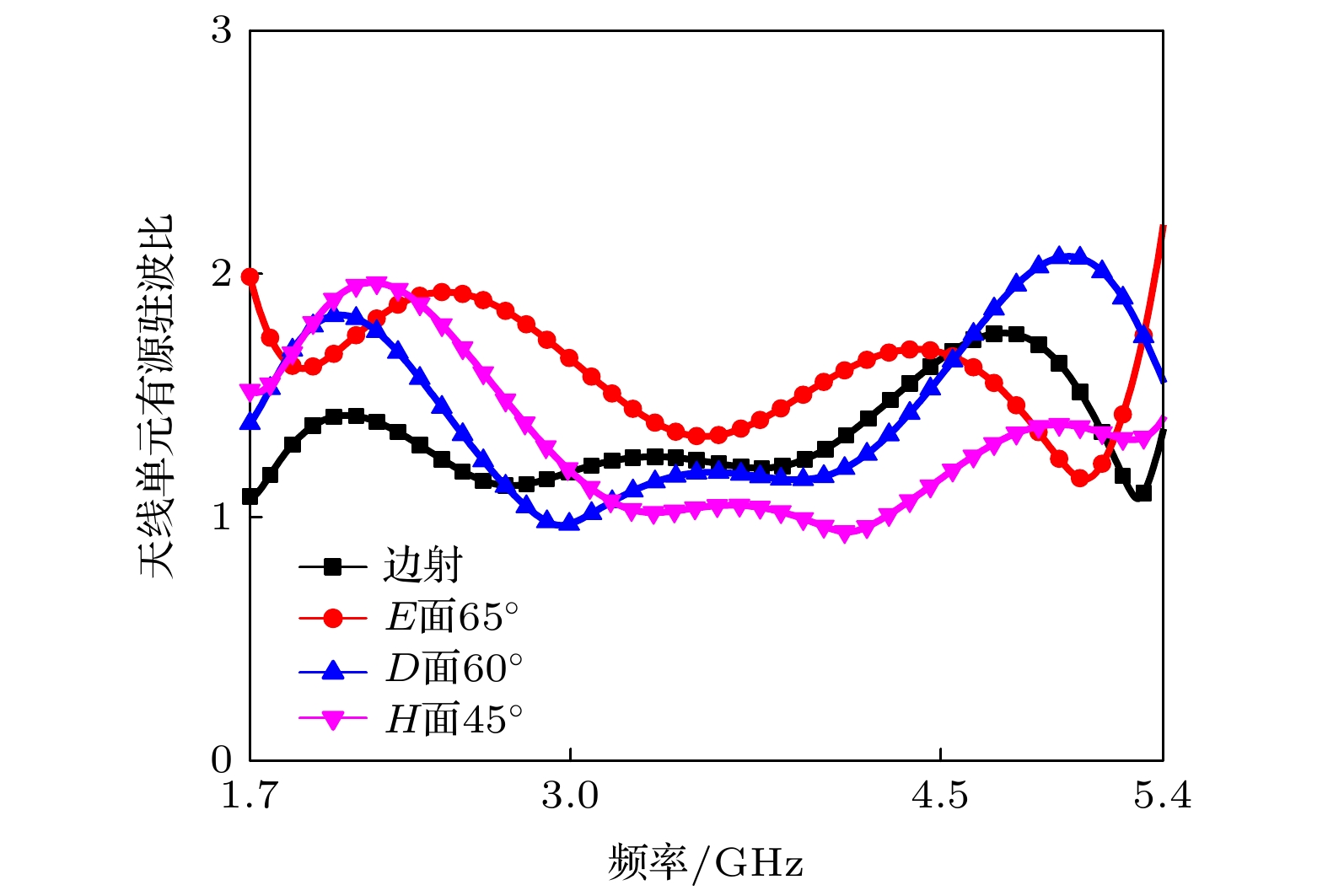
图 6 无限大阵列在边射、E面65°、H面45°和D面60°扫描时, 天线单元有源驻波比
Figure 6. Active VSWRs of the unit cell in infinite array simulation at broadside, 65° scanning in the E plane, 45° scanning in the H plane and 60° scanning in the D plane.
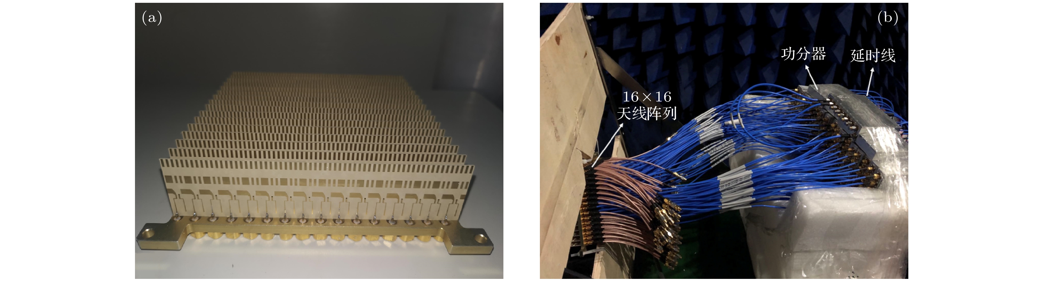
图 7 天线阵加工和测试 (a) 实际加工的16 × 16阵列; (b) 测试装置和测试环境
Figure 7. Antenna array fabrication and measurement: (a) Fabricated prototype of 16 × 16 antenna array; (b) measurement setup and environment.
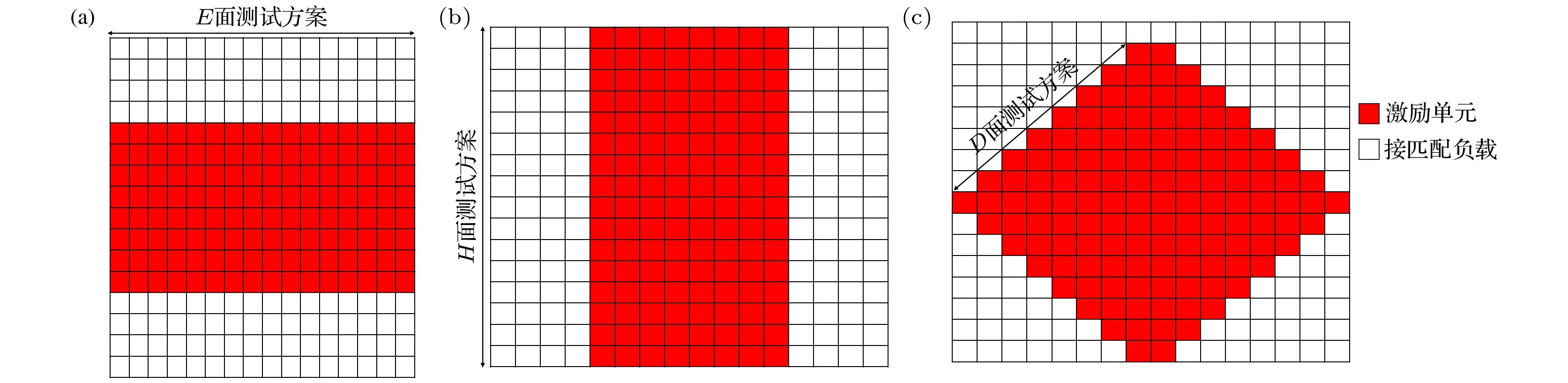
图 8 测试方案 (a) E面; (b) H面; (c) D面
Figure 8. Measurement scheme: (a) E plane; (b) H plane; (c) D plane.
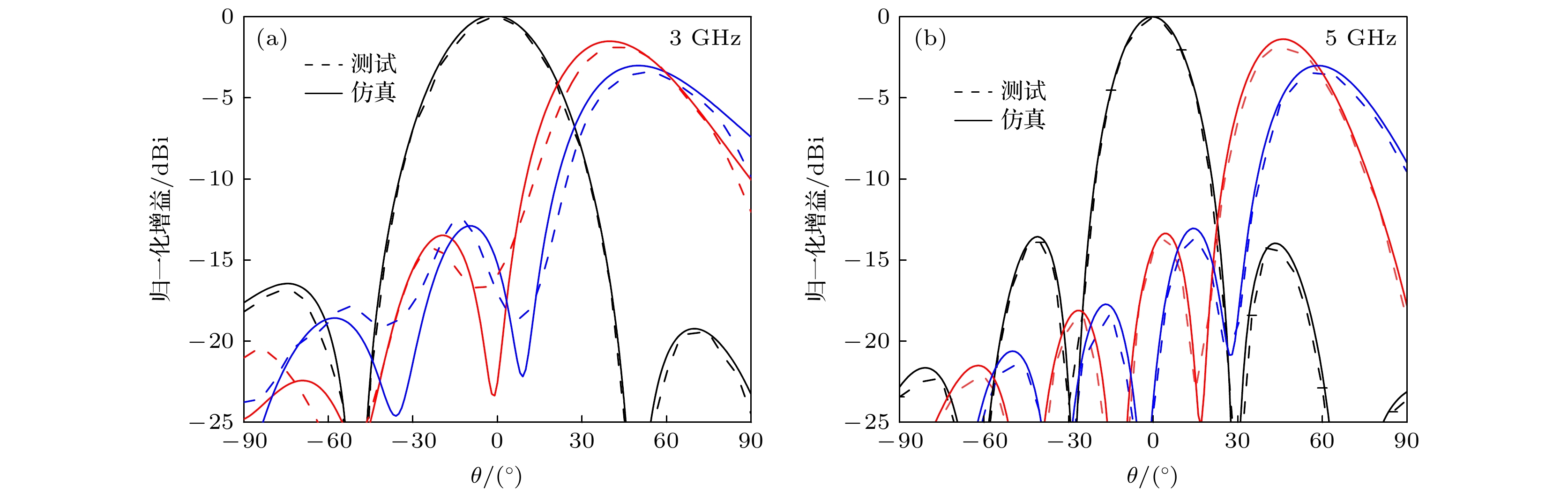
图 9 E面0°, 45°, 65°扫描时的归一化方向图 (a) 3 GHz; (b) 5 GHz
Figure 9. Normalized radiation patterns at 0°, 45° and 65° scanning in the E plane: (a) 3 GHz; (b) 5 GHz.
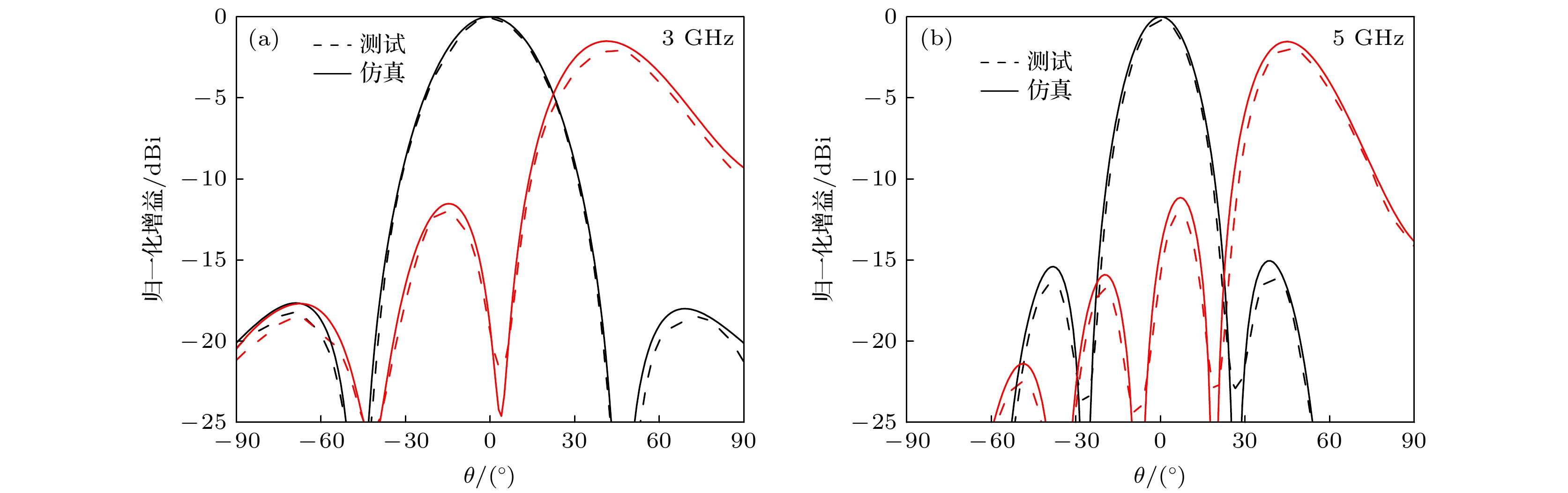
图 10 H面0°, 45°扫描时的归一化方向图 (a) 3 GHz; (b) 5 GHz
Figure 10. Normalized radiation patterns at 0° and 45° scanning in the H plane: (a) 3 GHz; (b) 5 GHz.

图 11 D面0°, 45°, 60°扫描时的归一化方向图 (a) 3 GHz; (b) 5 GHz
Figure 11. Normalized radiation patterns at 0°, 45° and 60° scanning in the D plane: (a) 3 GHz; (b) 5 GHz.
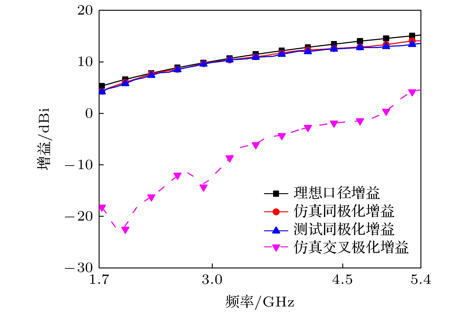
图 12 天线阵边射时, 测试结果和仿真结果对比
Figure 12. Comparisons between measured and simulated results at broadside radiation.
表 1 按相同辐射口径换算, 不同文献中天线阵的辐射功率对比
Table 1. Comparisons of radiated power of antenna arrays in literatures on the same conversion size radiation aperture.
参考文献 工作频率/GHz 单元周期/λhigh × λhigh 扫描角度 有源驻波比 单元个数 辐射效率 辐射功率/W [16] 0.75—3.85 GHz
(5.1∶1)0.36 × 0.36 E-70°
H-60°< 3 771 95% 732 [17] 0.68—5.00 GHz
(7.35∶1)0.45 × 0.45 E-45°
H-45°< 3 493 70% 345 [18] 0.80—4.38 GHz
(5.5∶1)0.35 × 0.35 E-70°
H-55°< 3 816 87% 710 [19] 3.13—11.63 GHz
(3.7∶1)0.36 × 0.36 E-75°
H-60°< 3 771 84% 647 [20] 6.5—14.5 GHz
(2.23∶1)0.45 × 0.45 E-50°
H-50°< 2 493 95% 468 [21] 7.8—13.5 GHz
(1.7∶1)0.45 × 0.39 E-70°
H-70°< 2 569 90% 512 本文设计 1.7—5.4 GHz
(3.2∶1)0.144 × 0.144 E-65°
H-45°< 2 4822 84% 4050  DownLoad: CSV
-
[1] Gold S H, Nusinovich G S 1997 Rev. Sci. Instrum. 68 3945
Google Scholar
[2] Chen Y, Zhang Y P 2005 IEEE Antennas Wirel. Propag. Lett. 53 3089
Google Scholar
[3] Choe H, Lim S 2014 IEEE Trans. Antennas Propag. 62 5497
Google Scholar
[4] Li J F, Chu Q X, Huang T W 2012 IEEE Trans. Antennas Propag. 60 482
Google Scholar
[5] 陈昭福, 黄华, 常安碧, 许州, 何琥, 雷禄容, 胡进光, 袁欢, 刘振帮 2014 63 238402
Google Scholar
Chen Z F, Huang H, Chang A B, Xu Z, He H, Lei L R, Hu J J, Yuan H, Liu Z B 2014 Acta Phys. Sin. 63 238402
Google Scholar
[6] Munk B A 2003 Finite Antenna Arrays and FSS (USA: Wiley-IEEE Press) pp181−213
[7] Yetisir E, Ghalichechian N, Volakis J L 2016 IEEE Trans. Antennas Propag. 64 4256
Google Scholar
[8] Hu C H, Wang B Z, Gao G F, Wang R, Xiao S Q, Ding X 2020 IEEE Antennas Wirel. Propag. Lett. 20 63
[9] Zhang Y H, Yang S W, Xiao S W, Chen Y K, Qu S W, Hu J 2019 IEEE Antennas Wirel. Propag. Lett. 18 378
Google Scholar
[10] Lim T B, Zhu L 2008 Proceedings of the IEEE MTT-S International Microwave Workshop Series on Art Miniaturizing RF Microwave and Passive Components Chengdu, China, December 14−15, 2008 p153
[11] Zhu L, Bu H, Wu K 2000 IEEE MTT-S International Microwave Symposium Digest Boston, USA, June 11−16, 2000 p315
[12] Magill E G, Wheeler H A 1966 IEEE Trans. Antennas Propag. 14 49
Google Scholar
[13] Smith D R, Schultz S 2002 Phys. Rev. B 65 195104
Google Scholar
[14] Hood A Z, Karacolak T, Topsakal E 2008 IEEE Antennas Wirel. Propag. Lett. 7 656
Google Scholar
[15] Cavallo D, Syed W H, Neto A 2017 IEEE Trans. Antennas Propag. 65 1788
Google Scholar
[16] Hu C H, Wang B Z, Wang R, Xiao S Q, Ding X 2020 IEEE Trans. Antennas Propag. 68 2788
Google Scholar
[17] Moulder W F, Sertel K, Volakis J L 2013 IEEE Trans. Antennas Propag. 61 5802
Google Scholar
[18] Bah A O, Qin P Y, Ziolkowski RW, Guo Y J, Bird T S 2019 IEEE Trans. Antennas Propag. 67 2332
Google Scholar
[19] Jiang Z G, Xiao S Q, Yao Z X, Wang B Z 2020 IEEE Trans. Antennas Propag. 68 7348
Google Scholar
[20] Syed W H, Cavallo D, Shivamurthy H T, Neto A 2015 IEEE Trans. Antennas Propag. 64 543
[21] Xia R L, Qu S W, Yang S W, Chen Y K 2018 IEEE Trans. Antennas Propag. 66 1767
Google Scholar


 DownLoad:


Catalog
Metrics
- Abstract views: 9179
- PDF Downloads: 140
- Cited By: 0
