


-
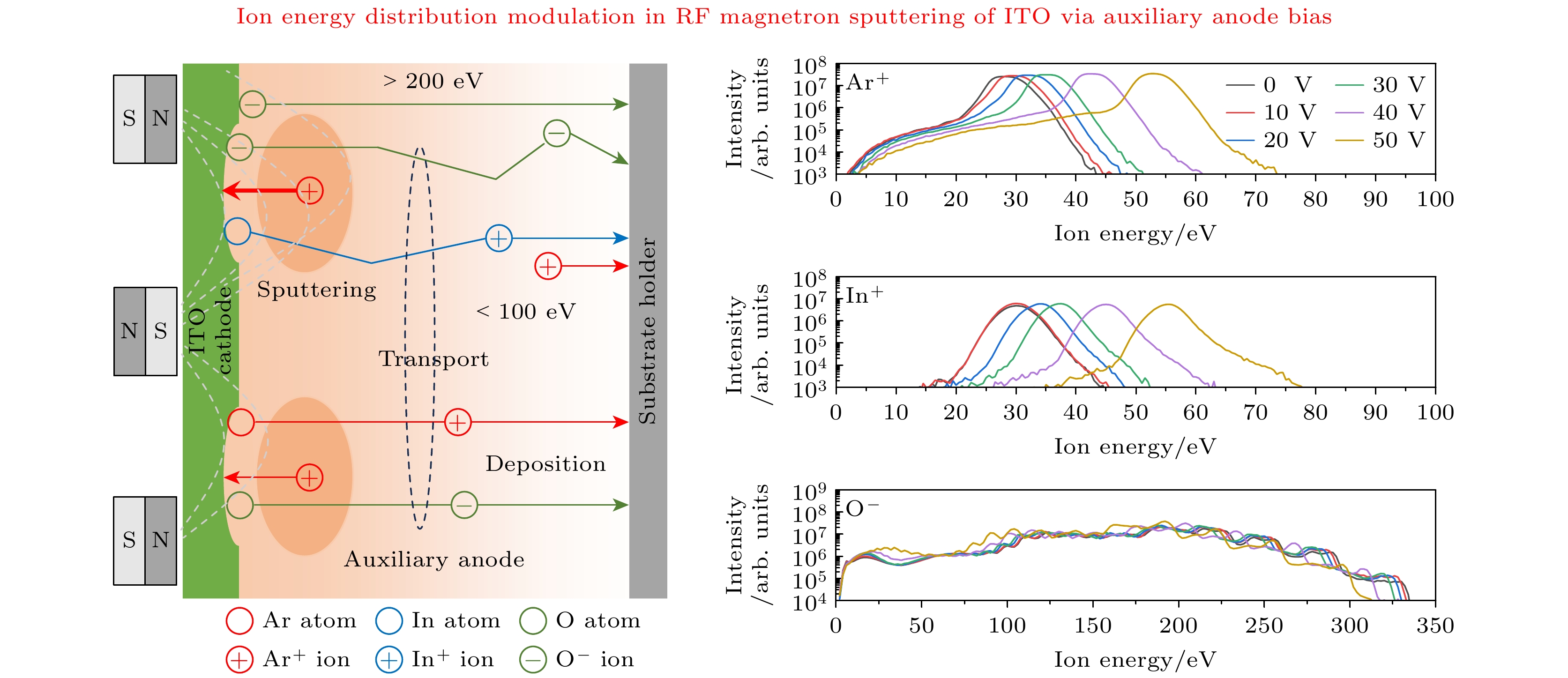
磁控溅射沉积透明导电氧化物薄膜过程中, 理解离子动力学过程是揭示“溅射损伤”机理并发展损伤抑制策略的关键. 本研究在纯Ar气氛下, 以氧化铟锡为阴极靶材, 系统探讨辅助阳极正偏压对射频磁控放电中基底入射离子能量分布的影响. 结果表明, 入射正离子包括O+, Ar+, In+, Sn+及多种金属氧化物分子离子和双电荷离子, 其能量由溅射原子的初始逸出能与等离子体电势共同决定, 并随辅助阳极偏压的升高而增强. 负离子源于阴极溅射, 其中O–和$\rm O_2^-$负离子能量分布宽广且呈多峰结构, 与阴极电压、等离子体电势的射频振荡及离子输运的弛豫效应密切相关. 金属氧化物负离子(InO–, $\rm InO_2^-$, SnO–和$\rm SnO_2^-$)对射频鞘响应滞后, 其高能峰向阴极偏置电压收敛. 高能负离子是导致“溅射损伤”的主要原因, 施加辅助阳极正偏压能有效降低其能量, 为透明导电氧化物薄膜损伤抑制提供潜在解决方案.Understanding the dynamics of ions in the magnetron sputtering process of transparent conductive oxide (TCO) films is essential for clarifying the mechanisms of sputtering-induced damage and developing effective suppression strategies. In this work, indium tin oxide (ITO) is used as a cathode target in an RF magnetron sputtering system operating under pure argon atmosphere, and a positively biased auxiliary anode is introduced to modulate the plasma potential and investigate its effect on the ion energy distribution functions (IEDFs) at the substrate position. The ion energy spectra are measured using a commercial energy–mass spectrometer (EQP 1000, Hiden), and the plasma parameters such as potential and electron density are characterized using a radio-frequency compensated Langmuir probe. The results show that the incident positive ions consist mainly of O+, Ar+, In+, Sn+, as well as multiple metal oxide molecular and doubly charged ions. Their energies are determined by the combined effects of the initial ejection or backscattering energy of sputtered particles and the plasma potential. Increasing the auxiliary anode bias leads to an elevation of the plasma potential, thereby enhancing both the kinetic energy and flux of positive ions. In contrast, negative ions such as O– and $\rm O_2^-$ originate predominantly from cathode sputtering, exhibiting broad, multi-peaked energy distributions that are strongly influenced by RF oscillations of the cathode voltage and plasma potential, as well as relaxation effects during ion transport. Heavier metal oxide negative ions ($\rm InO^-, \;InO_2^-,\; SnO^-,\; SnO_2^-$) respond more slowly to RF sheath modulation, with their high-energy peaks converging toward the cathode bias potential. Applying a positive auxiliary anode bias effectively reduces the cathode bias voltage, thereby suppressing the high-energy tail of negative ions without significantly affecting their total energy-integrated intensity. This demonstrates that auxiliary anode biasing provides an effective means for adjusting the ion energy distributions in magnetron sputtering discharges. The proposed approach provides a potential pathway for mitigating sputtering-induced damage and improving the structural and electronic quality of ITO films. Future work will focus on correlating the measured ion energy modulation with comprehensive film characterizations—including optical, electrical, and interfacial analyses—to further verify the physical mechanisms and evaluate the practical effectiveness of damage suppression during TCO deposition.
-
Keywords:
- radio frequency magnetron sputtering /
- indium tin oxide (ITO) /
- ion energy distribution /
- auxiliary anode
[1] Chavan G T, Kim Y, Khokhar M Q, Hussain S Q, Cho E, Yi J, Ahmad Z, Rosaiah P, Jeon C 2023 Nanomaterials 13 1226
 Google Scholar
[2] Suemori K 2023 Org. Electron. 116 106764
Google Scholar
[3] Li S, Pomaska M, Lambertz A, et al. 2021 Joule 5 1535
Google Scholar
[4] Park G, Lim H, Jun D Y, Moon J, Otgongerel Z, Park J W, Kim J, Kim S H 2025 Cell Rep. Phys. Sci. 6 102619
Google Scholar
[5] Zhao M J, Zhang J F, Huang J, et al. 2022 Vacuum 200 111034
Google Scholar
[6] Hossain M I, Salhi A, Zekri A, Abutaha A, Tong Y, Mansour S 2025 Results in Surfaces and Interfaces 18 100383
Google Scholar
[7] 杨志伟, 韩圣浩, 杨田林, 赵俊卿, 马瑾, 马洪磊 2000 49 1196
Google Scholar
Yang Z W, Han S H, Yang T L, Zhao J Q, Ma J, Ma H L 2000 Acta Phys. Sin. 49 1196
Google Scholar
[8] Ishibashi S, Higuchi Y, Ota Y, Nakamuraet K 1990 J. Vac. Sci. Technol., A 8 1403
Google Scholar
[9] Dewald W, Sittinger V, Werner W, Jacobs C, Szyszka B 2009 Thin Solid Films 518 1085
Google Scholar
[10] Le A H T, Dao V A, Pham D P, et al. 2019 Sol. Energy Mater. Sol. Cells 192 36
Google Scholar
[11] Konishi T, Ohdaira K 2017 Thin Solid Films 635 73
Google Scholar
[12] Caudevilla D, García-Hemme E, San Andrés E, et al. 2022 Mater. Sci. Semicond. Process 137 106189
Google Scholar
[13] Qiu D, Duan W, Lambertzet A, et al. 2022 Sol. Energy 231 578
Google Scholar
[14] Petroski K A, Sagas J C 2020 Vacuum 182 109703
Google Scholar
[15] Hippler R, Cada M, Hubicka Z 2021 J. Vac. Sci. Technol., A 39 043007
Google Scholar
[16] Hippler R, Cada M, Hubicka Z 2021 Plasma Sources Sci. Technol. 30 045003
Google Scholar
[17] Huang T Y, Mo C C, Cui M L, et al. 2024 Vacuum 221 112848
Google Scholar
[18] Welzel T, Ellmer K 2013 J. Phys. D: Appl. Phys. 46 315202
Google Scholar
[19] Toyoda H, Goto K, Ishijima T, et al. 2009 Appl. Phys. Express 2 126001
Google Scholar
[20] Li M Y, Mo C C, Chen J L, et al. 2024 Plasma Sci. Technol. 26 075506
Google Scholar
[21] Ellmer K, Wendt R, Wiesemann K 2003 Int. J. Mass Spectrom. 223-224 679
[22] Hamers E A G, Sark W G J H M, Bezemer J, et al. 1998 Int. J. Mass. Spectrom. 173 91
Google Scholar
[23] Belkind A, Jansen F 1998 Surf. Coat. Technol. 99 52
Google Scholar
[24] Coburn J W, Kay E 1972 J. Appl. Phys. 43 4965
Google Scholar
[25] Woller K B, Whyte D G, Wright G M 2017 Phys. Plasmas 24 053513
Google Scholar
[26] Thompson M W 1968 Philosophical Magazine 18 377
Google Scholar
[27] Betz G, Husinsky W 2004 Philos. Trans. R. Soc. London, Ser. A 362 177
Google Scholar
[28] Pullins S H, Dressler R A, Torrents R, Gerlich D 2000 Z. Phys. Chem. 214 1279
-
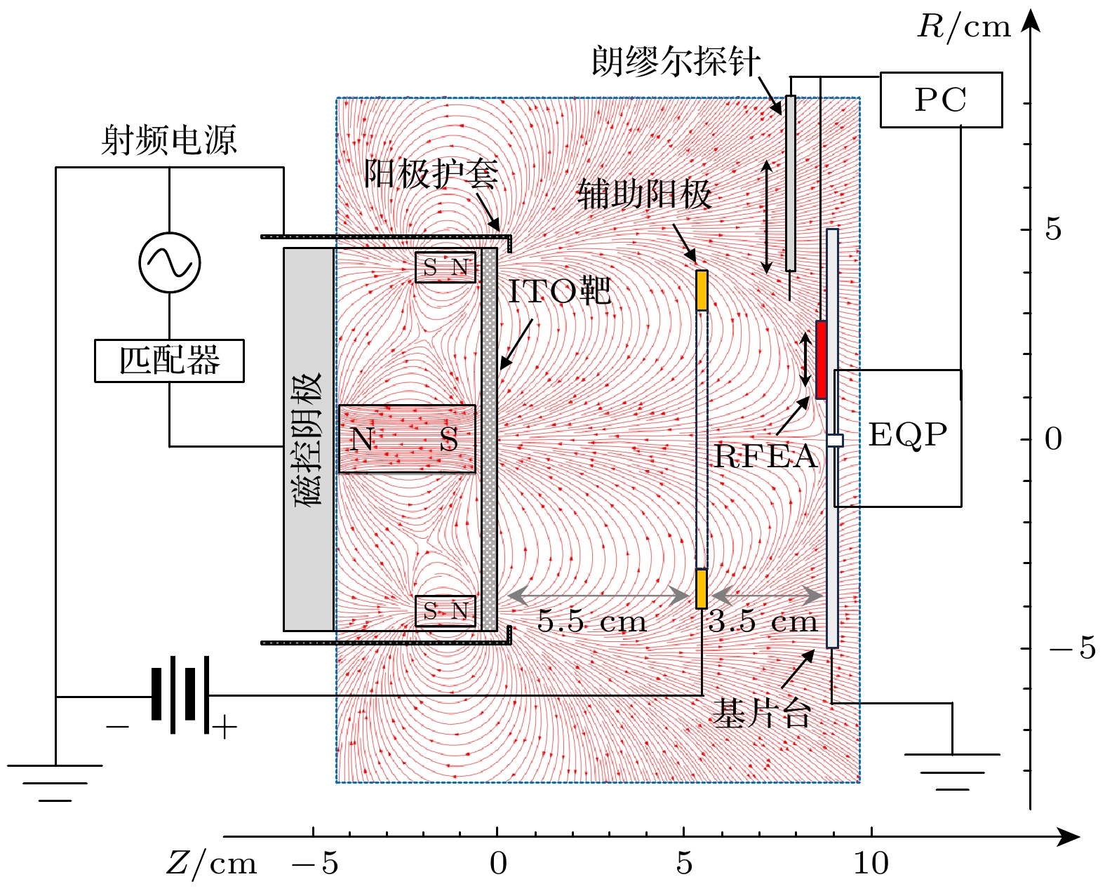
图 1 基于辅助阳极的ITO射频磁控溅射装置及等离子体诊断系统
Fig. 1. RF magnetron sputtering system for ITO film deposition with auxiliary anode and integrated plasma diagnostics.
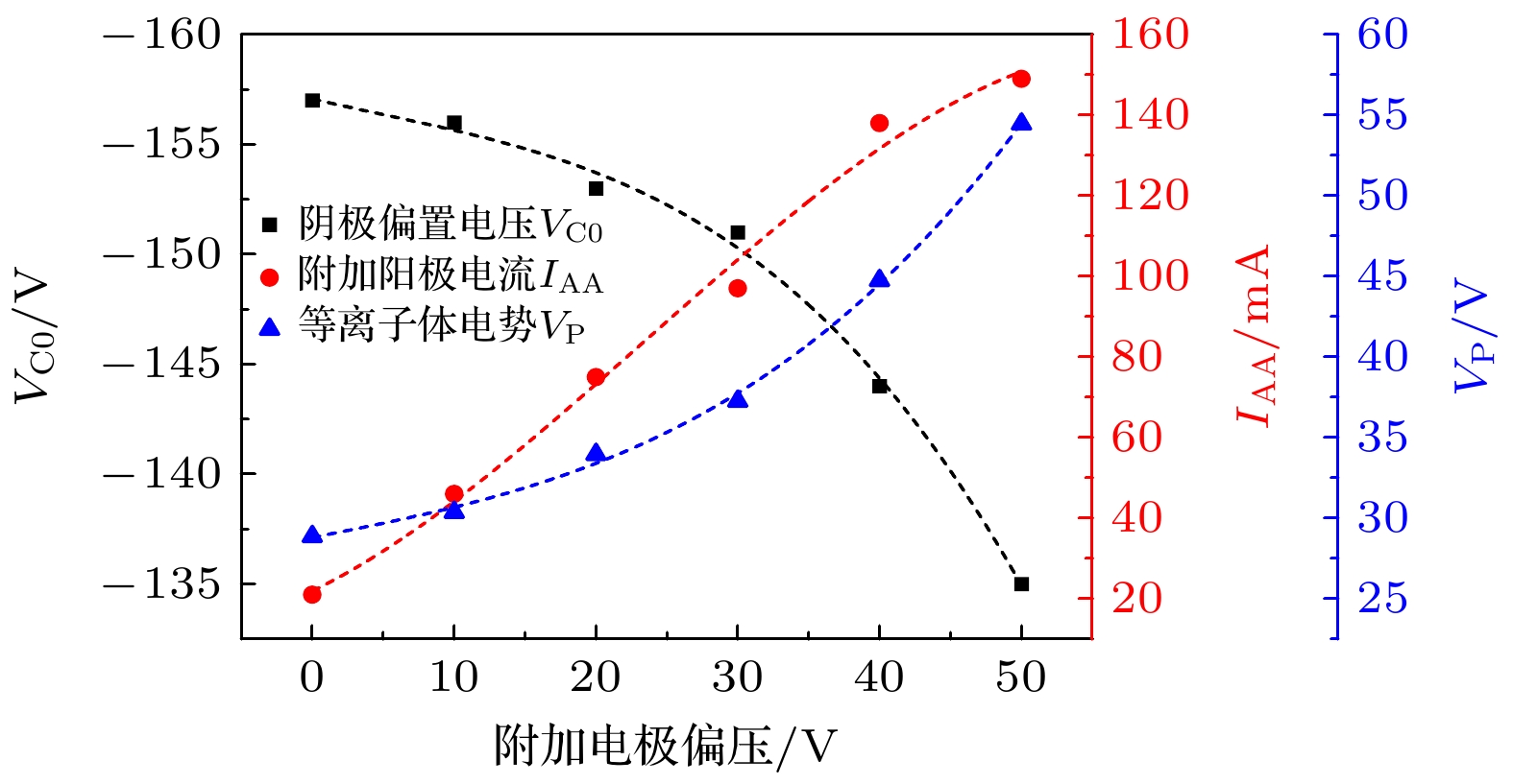
图 2 ITO射频磁控放电中, 阴极偏置电压$ {V}_{\mathrm{C}0} $、附加阳极电流$ {I}_{\mathrm{A}\mathrm{A}} $及等离子体电势$ {V}_{\mathrm{P}} $随辅助阳极偏压$ {V}_{\mathrm{A}\mathrm{A}} $的变化关系
Fig. 2. Cathode bias voltage $ {V}_{\mathrm{C}0} $, auxiliary anode current $ {I}_{\mathrm{A}\mathrm{A}} $, and plasma potential $ {V}_{\mathrm{P}} $ as functions of the auxiliary anode bias $ {V}_{\mathrm{A}\mathrm{A}} $ during an ITO RFMS discharge.
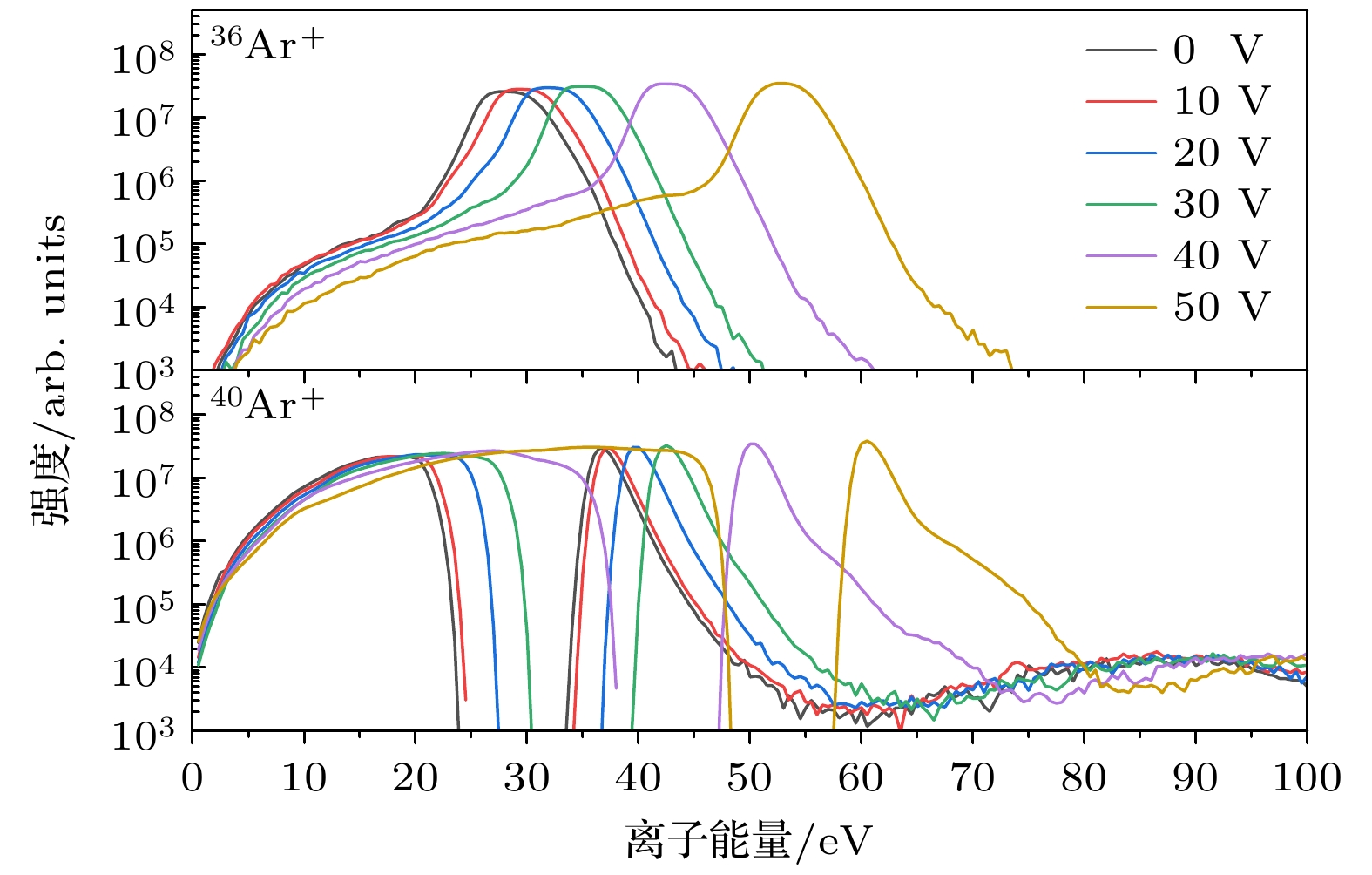
图 3 ITO射频磁控放电中, 不同辅助阳极电压(0—+50 V)对氩同位素离子36Ar+ (m/z = 36)和40Ar+ (m/z = 40)能量分布的影响(气压: 0.6 Pa, 放电功率: 100 W)
Fig. 3. Effect of different auxiliary anode voltages (0 to +50 V) on the energy distributions of argon isotope ions 36Ar+ (m/z = 36) and 40Ar+ (m/z = 40) in an ITO RFMS discharge (Gas pressure: 0.6 Pa, discharge power: 100 W).
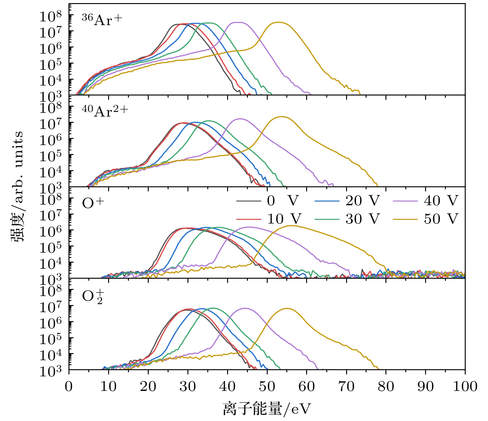
图 4 ITO射频磁控放电中, 不同辅助阳极偏压(0— +50 V)对36Ar+(m/z = 36), 40Ar2+(m/z = 20), O+(m/z = 16)和${\mathrm{O}}_2^+ $(m/z = 32)离子能量分布的影响(气压: 0.6 Pa, 放电功率: 100 W)
Fig. 4. Energy distributions of positive charged 36Ar+ (m/z = 36), 40Ar+ (m/z = 20), O+ (m/z = 16), and ${\mathrm{O}}_2^+ $ (m/z = 32) ions in an ITO RFMS discharge (Gas pressure: 0.6 Pa, discharge power: 100 W). Measurements have been carried out for different auxiliary anode voltages ranging from 0 to +50 V.
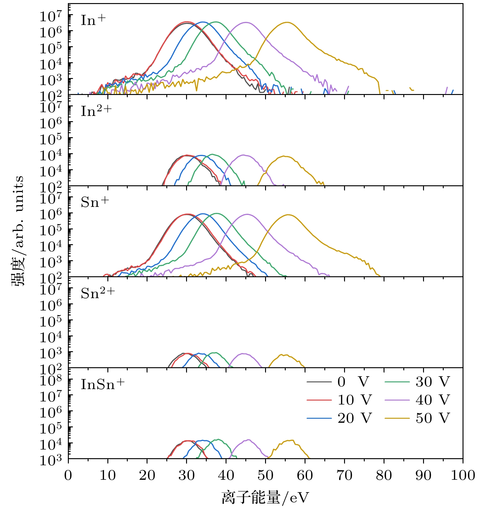
图 5 在ITO射频磁控放电中, 不同辅助阳极电压(0—+50 V)对In+(m/z = 115), In2+(m/z = 57.5), 118Sn+(m/z = 118), 118Sn2+(m/z = 59)和InSn+(m/z = 233)等金属离子能量分布的影响(气压: 0.6 Pa, 放电功率: 100 W)
Fig. 5. Effect of different auxiliary anode voltages (0 to +50 V) on the energy distributions of metal ions In+ (m/z = 115), In2+ (m/z = 57.5), 118Sn+ (m/z = 118), 118Sn2+ (m/z = 59), and InSn+ (m/z = 233) in an ITO RFMS discharge (Gas pressure: 0.6 Pa, discharge power: 100 W).
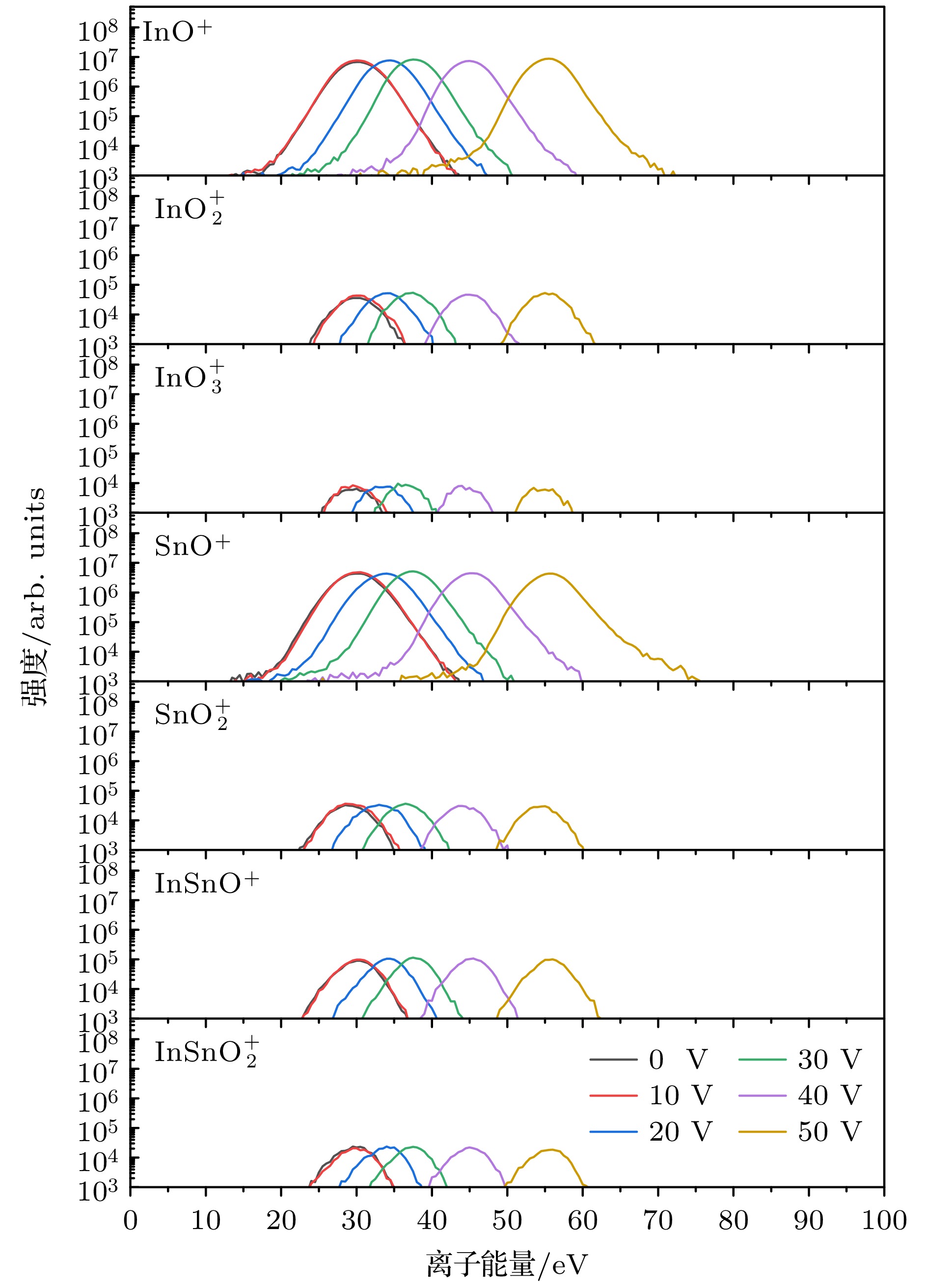
图 6 ITO射频磁控放电中, 不同辅助阳极电压(0—+50 V)对InO+(m/z = 131), ${\mathrm{InO}}_2^+ $(m/z = 147), ${\mathrm{InO}}_3^+ $(m/z = 163), SnO+(m/z = 134), ${\mathrm{SnO}}_2^+ $(m/z = 150), InSnO+(m/z = 249)和${\mathrm{InSnO}}_2^+ $(m/z = 265)等金属氧化物离子能量分布的影响(气压: 0.6 Pa, 放电功率: 100 W)
Fig. 6. Effect of different auxiliary anode voltages (0 to +50 V) on the energy distributions of metal oxide ions InO+ (m/z = 131), ${\mathrm{InO}}_2^+ $ (m/z = 147), ${\mathrm{InO}}_3^+ $ (m/z = 163), SnO+ (m/z = 134), ${\mathrm{SnO}}_2^+ $ (m/z = 150), InSnO+ (m/z = 249), and ${\mathrm{InSnO}}_2^+ $ (m/z = 265) in an ITO RFMS discharge (Gas pressure: 0.6 Pa, discharge power: 100 W).
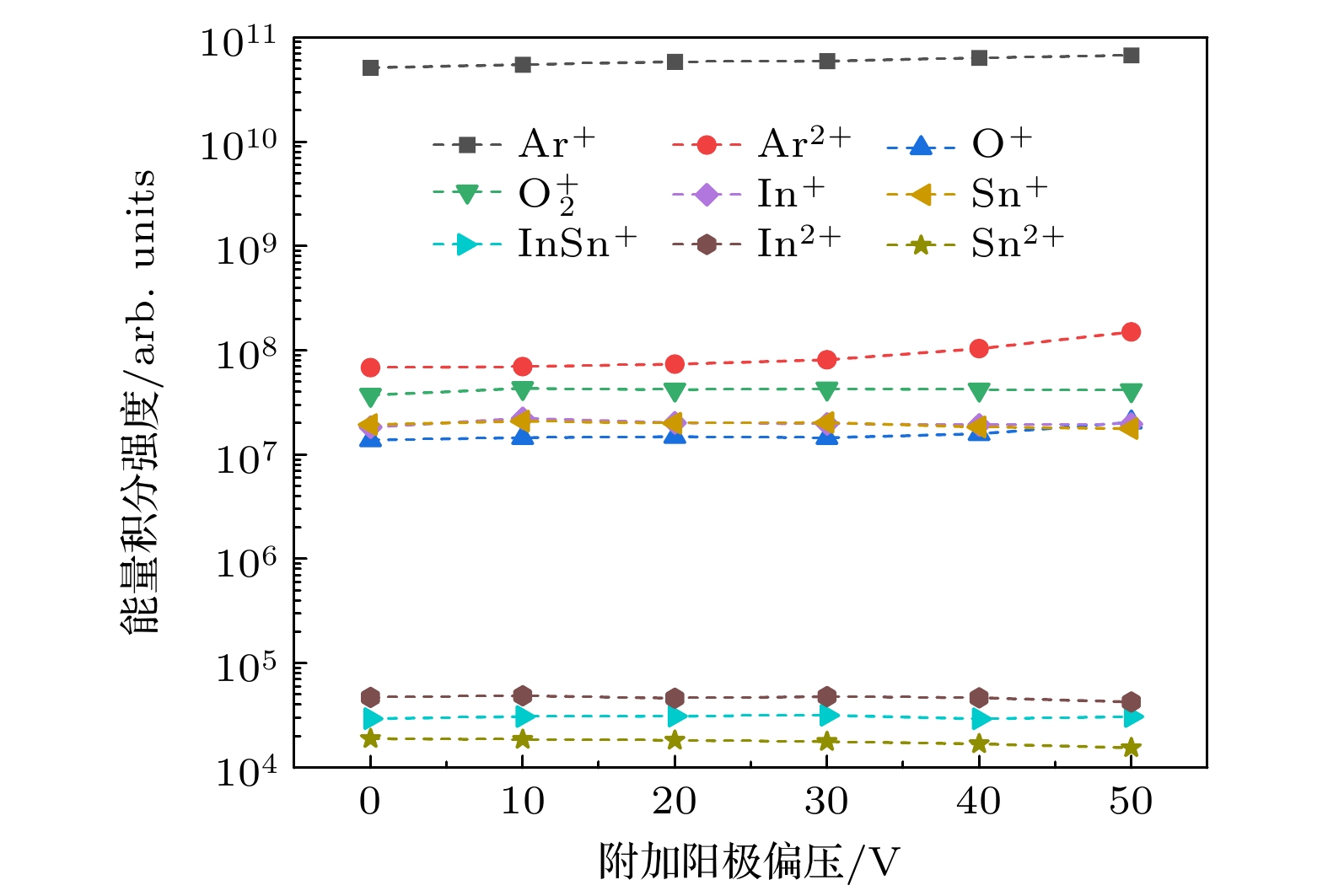
图 7 ITO射频磁控放电中, 不同辅助阳极电压(0—+50 V)下单电荷离子(Ar+, O+, O2+, In+, Sn+和InSn+)及双电荷离子(Ar2+, In2+和Sn2+)的能量积分强度(气压: 0.6 Pa, 放电功率: 100 W)
Fig. 7. Energy-integrated count rates of singly charged ions (Ar+, O+, O2+, In+, Sn+ and InSn+) and doubly charged ions (Ar2+, In2+, and Sn2+) in an ITO RFMS discharge at different auxiliary anode voltages from 0 to +50 V (Gas pressure: 0.6 Pa, discharge power: 100 W).
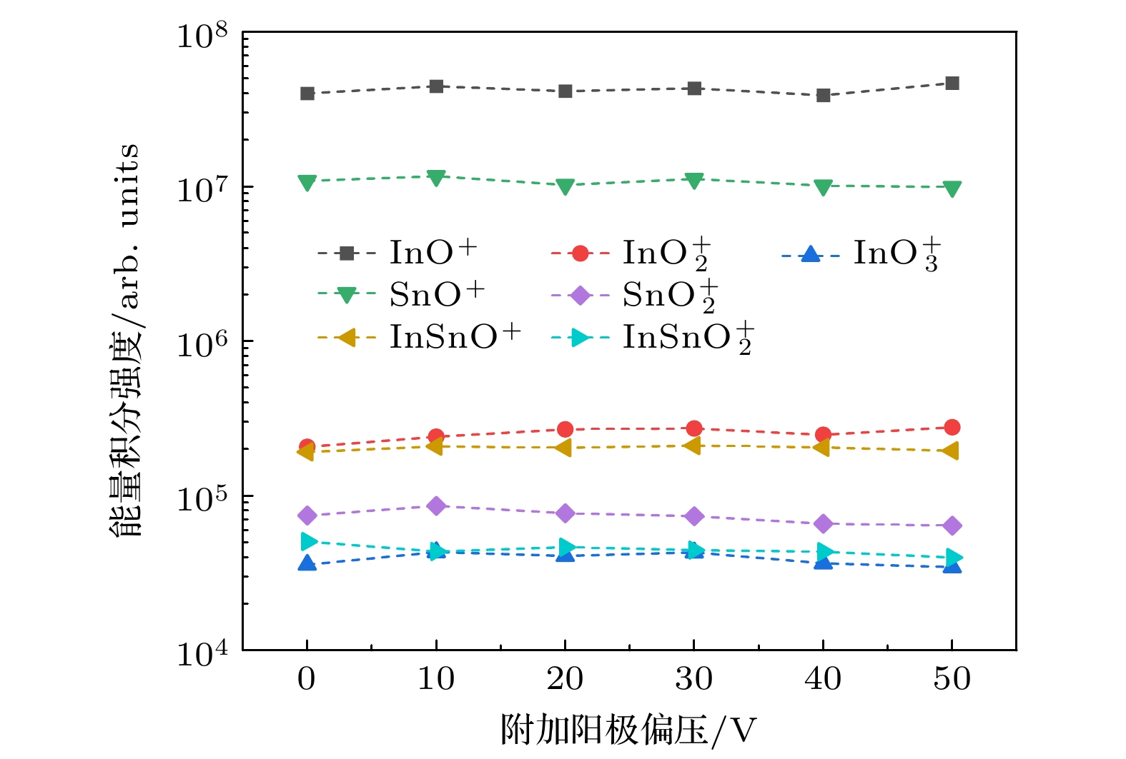
图 8 ITO射频磁控放电中, 不同辅助阳极电压(0—+50 V)下金属氧化物离子(InO+, ${\mathrm{InO}}_2^+ $, ${\mathrm{InO}}_3^+ $, SnO+, ${\mathrm{SnO}}_2^+ $, InSnO+和${\mathrm{InSnO}}_2^+ $)的能量积分强度(气压: 0.6 Pa, 放电功率: 100 W)
Fig. 8. Energy-integrated count rates of metal oxide ions (InO+, ${\mathrm{InO}}_2^+ $, ${\mathrm{InO}}_3^+ $, SnO+, $ {\mathrm{SnO}}_2^+$, InSnO+, and ${\mathrm{InSnO}}_2^+ $) in an ITO RFMS discharge at different auxiliary anode voltages from 0 to +50 V (Gas pressure: 0.6 Pa, discharge power: 100 W).
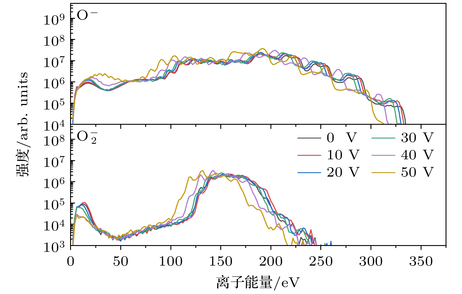
图 9 ITO射频磁控放电中, 不同辅助阳极偏压(0—+50 V)对O–(m/z = 16)和${\mathrm{O}}_2^- $(m/z = 32)负离子能量分布的影响(气压: 0.6 Pa, 放电功率: 100 W)
Fig. 9. Effect of different auxiliary anode voltages (0 to +50 V) on the energy distributions of O– (m/z = 16) and ${\mathrm{O}}_2^- $ (m/z = 32) negative ions in an ITO RFMS discharge (Gas pressure: 0.6 Pa, discharge power: 100 W).
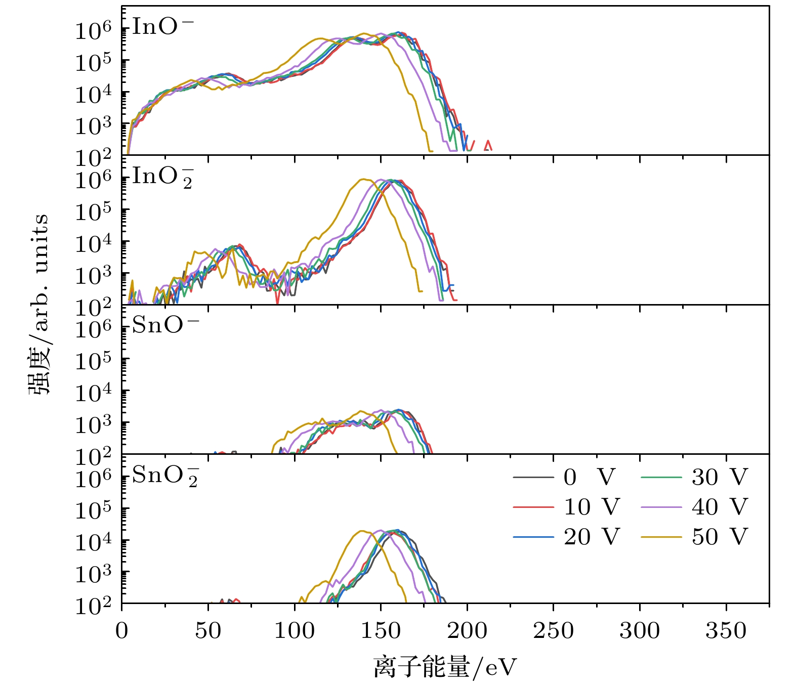
图 10 ITO射频磁控放电中, 不同辅助阳极电压(0—+50 V)对InO–(m/z = 131), ${\mathrm{InO}}_2^- $(m/z = 147), SnO–(m/z = 134)和${\mathrm{SnO}}_2^- $(m/z = 150)负离子能量分布的影响(气压: 0.6 Pa, 放电功率: 100 W)
Fig. 10. Effect of different auxiliary anode voltages (0 to +50 V) on the energy distributions of negative ions InO– (m/z = 131), ${\mathrm{InO}}_2^- $ (m/z = 147), SnO– (m/z = 134), and ${\mathrm{SnO}}_2^- $ (m/z = 150) in an ITO RFMS discharge (Gas pressure: 0.6 Pa, discharge power: 100 W).
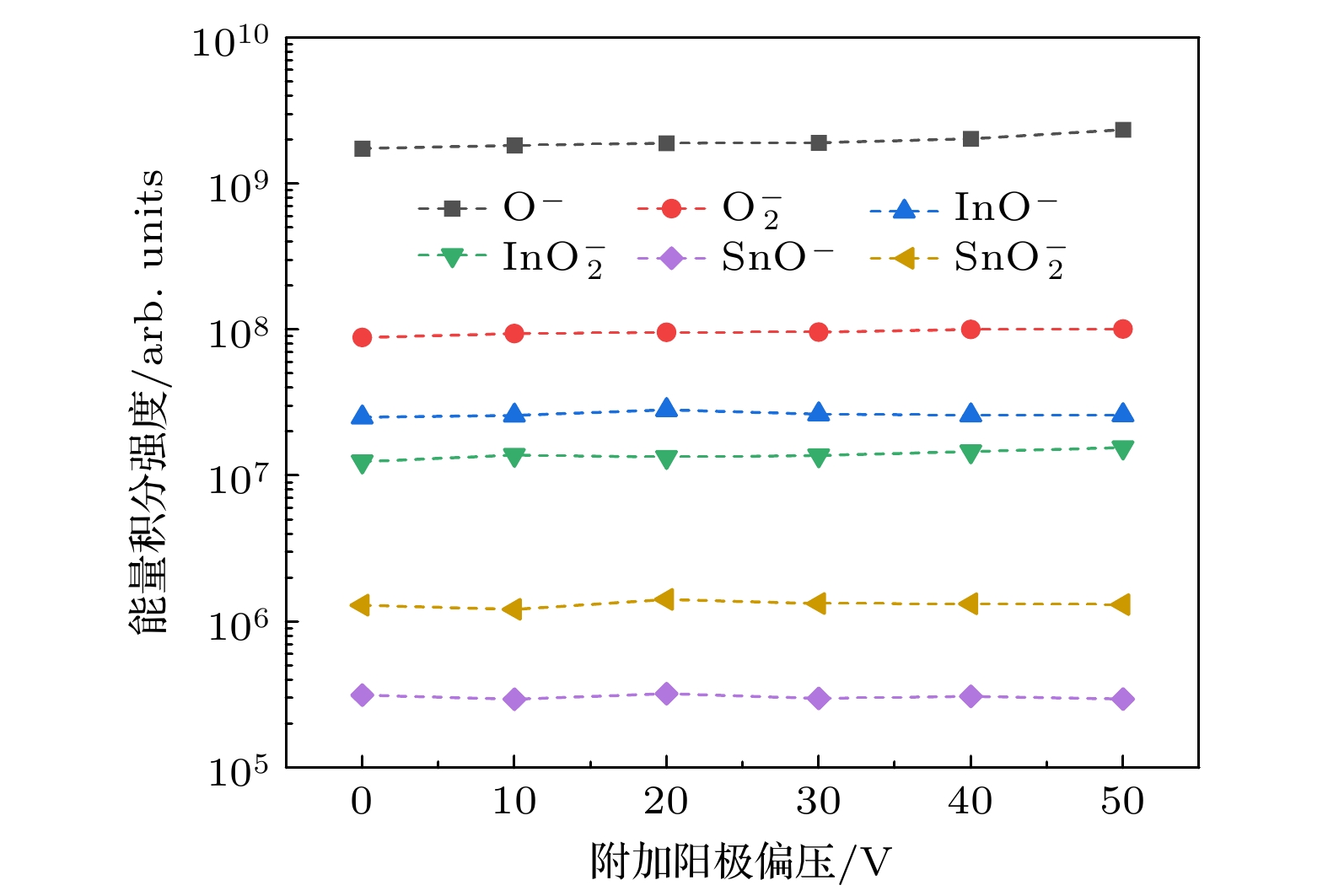
图 11 ITO射频磁控放电中, 不同辅助阳极电压(0—+50 V)下负离子(O–, $\rm O_2^- $, InO–, ${\mathrm{InO}}_2^- $, SnO–和${\mathrm{SnO}}_2^- $)的能量积分强度(气压: 0.6 Pa, 放电功率: 100 W)
Fig. 11. Energy-integrated intensities of negative ions (O–, $\rm O_2^-$, InO–, $ {\mathrm{InO}}_2^- $, SnO–, and ${\mathrm{SnO}}_2^- $) in an ITO RFMS discharge at different auxiliary anode voltages from 0 to +50 V (Gas pressure: 0.6 Pa, discharge power: 100 W).
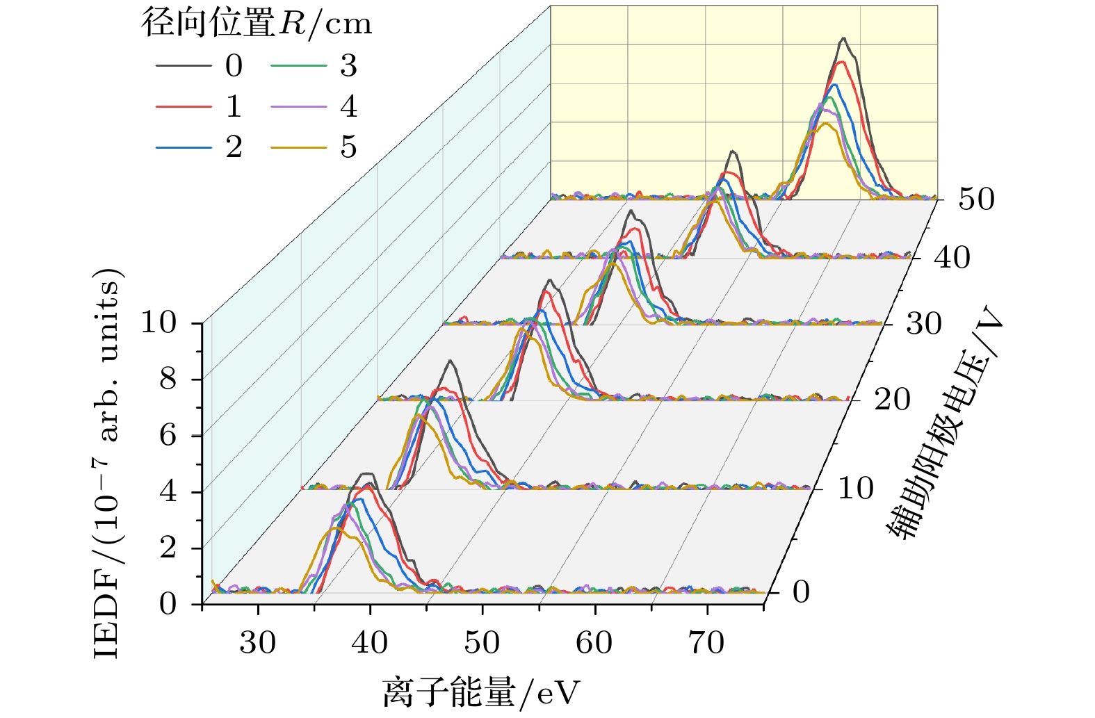
图 12 ITO射频磁控放电中, 不同辅助阳极电压(0—+50 V)下基片台表面IEDFs的径向分布情况(气压: 0.6 Pa, 放电功率: 100 W)
Fig. 12. Radial distributions of IEDFs on the substrate surface under different auxiliary anode voltages from 0 to +50 V during ITO RFMS discharge (Gas pressure: 0.6 Pa, discharge power: 100 W).
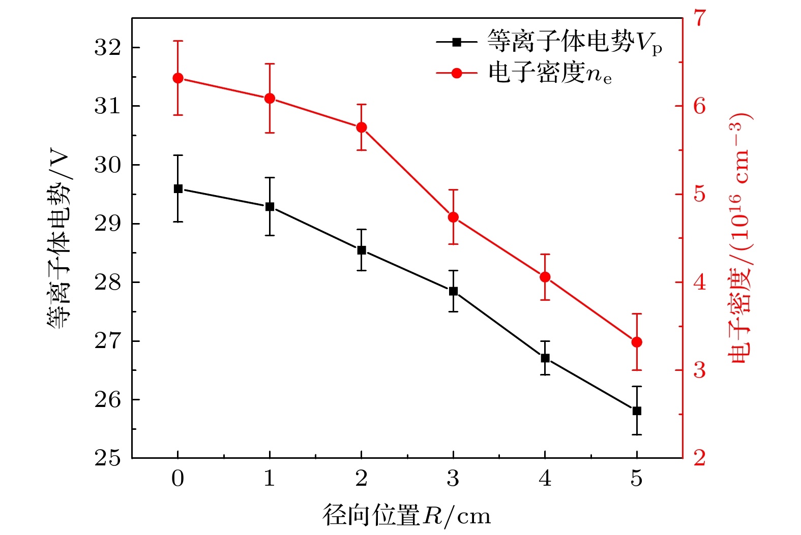
图 13 ITO射频磁控放电中, 辅助阳极电压$ {V}_{\mathrm{A}\mathrm{A}}=0\;\mathrm{V} $条件下近基片台表面等离子体电势Vp及电子密度ne的径向分布情况(气压: 0.6 Pa, 放电功率: 100 W)
Fig. 13. Radial distributions of plasma potential Vp and electron density ne near the substrate surface under auxiliary anode voltage $ {V}_{\mathrm{A}\mathrm{A}}=0\;\mathrm{V} $ during ITO RF magnetron discharge (Gas pressure: 0.6 Pa, discharge power: 100 W).
-
[1] Chavan G T, Kim Y, Khokhar M Q, Hussain S Q, Cho E, Yi J, Ahmad Z, Rosaiah P, Jeon C 2023 Nanomaterials 13 1226
Google Scholar
[2] Suemori K 2023 Org. Electron. 116 106764
Google Scholar
[3] Li S, Pomaska M, Lambertz A, et al. 2021 Joule 5 1535
Google Scholar
[4] Park G, Lim H, Jun D Y, Moon J, Otgongerel Z, Park J W, Kim J, Kim S H 2025 Cell Rep. Phys. Sci. 6 102619
Google Scholar
[5] Zhao M J, Zhang J F, Huang J, et al. 2022 Vacuum 200 111034
Google Scholar
[6] Hossain M I, Salhi A, Zekri A, Abutaha A, Tong Y, Mansour S 2025 Results in Surfaces and Interfaces 18 100383
Google Scholar
[7] 杨志伟, 韩圣浩, 杨田林, 赵俊卿, 马瑾, 马洪磊 2000 49 1196
Google Scholar
Yang Z W, Han S H, Yang T L, Zhao J Q, Ma J, Ma H L 2000 Acta Phys. Sin. 49 1196
Google Scholar
[8] Ishibashi S, Higuchi Y, Ota Y, Nakamuraet K 1990 J. Vac. Sci. Technol., A 8 1403
Google Scholar
[9] Dewald W, Sittinger V, Werner W, Jacobs C, Szyszka B 2009 Thin Solid Films 518 1085
Google Scholar
[10] Le A H T, Dao V A, Pham D P, et al. 2019 Sol. Energy Mater. Sol. Cells 192 36
Google Scholar
[11] Konishi T, Ohdaira K 2017 Thin Solid Films 635 73
Google Scholar
[12] Caudevilla D, García-Hemme E, San Andrés E, et al. 2022 Mater. Sci. Semicond. Process 137 106189
Google Scholar
[13] Qiu D, Duan W, Lambertzet A, et al. 2022 Sol. Energy 231 578
Google Scholar
[14] Petroski K A, Sagas J C 2020 Vacuum 182 109703
Google Scholar
[15] Hippler R, Cada M, Hubicka Z 2021 J. Vac. Sci. Technol., A 39 043007
Google Scholar
[16] Hippler R, Cada M, Hubicka Z 2021 Plasma Sources Sci. Technol. 30 045003
Google Scholar
[17] Huang T Y, Mo C C, Cui M L, et al. 2024 Vacuum 221 112848
Google Scholar
[18] Welzel T, Ellmer K 2013 J. Phys. D: Appl. Phys. 46 315202
Google Scholar
[19] Toyoda H, Goto K, Ishijima T, et al. 2009 Appl. Phys. Express 2 126001
Google Scholar
[20] Li M Y, Mo C C, Chen J L, et al. 2024 Plasma Sci. Technol. 26 075506
Google Scholar
[21] Ellmer K, Wendt R, Wiesemann K 2003 Int. J. Mass Spectrom. 223-224 679
[22] Hamers E A G, Sark W G J H M, Bezemer J, et al. 1998 Int. J. Mass. Spectrom. 173 91
Google Scholar
[23] Belkind A, Jansen F 1998 Surf. Coat. Technol. 99 52
Google Scholar
[24] Coburn J W, Kay E 1972 J. Appl. Phys. 43 4965
Google Scholar
[25] Woller K B, Whyte D G, Wright G M 2017 Phys. Plasmas 24 053513
Google Scholar
[26] Thompson M W 1968 Philosophical Magazine 18 377
Google Scholar
[27] Betz G, Husinsky W 2004 Philos. Trans. R. Soc. London, Ser. A 362 177
Google Scholar
[28] Pullins S H, Dressler R A, Torrents R, Gerlich D 2000 Z. Phys. Chem. 214 1279


 下载:
下载:


计量
- 文章访问数: 623
- PDF下载量: 15
- 被引次数: 0
