-
Full polarization imaging can obtain more information about target, which has a broad application prospect in the target detection, researches of atmospheric characteristics, and medical diagnosis. This paper develops an imaging system of polarized skylight pattern of full polarization for obtaining the information about full polarization rapidly. Meanwhile, aiming at the problem that the error of the light intensity image obtained by the system due to the different “behavior” of the system transmission matrix is brought into the solution of the target Stokes vector, this paper analyzes the condition number and determinant of the system transmission matrix. Firstly, an objective function is established by combining the three sets of condition numbers and the determinant. Therefore, the problem of solving the optimal transmission matrix is transformed into a multi-condition extremal problem. And then the objective function is minimized to determine the optimal angle of the transmission matrix when the 1 norm condition number, 2 norm condition number and ∞ norm condition number reach the minimum value and the determinant reaches the maximum value. In addition, in order to improve the measurement accuracy, the delay components of quarter wave plate, extinction ratio of polarizer, and the transmission matrix of the system are calibrated. Optimization contrast experiment and outfield experiment are performed. The entropy, mean, and standard deviation are used to quantify the optimized results of the angle of polarization, degree of polarization, and degree of linear polarization. ∆Aop is defined as the difference in absolute value of angle of polarization between the two sides of the symmetry axis to verify the optimization performance of angle of polarization. Experimental results show that the polarization angle error after optimization is reduced by more than 10% compared with that before optimization; the error of the band of maximum polarization and the error of the neutral zone in the degree of polarization and linear polarization also decline to different degrees compared with before optimization. On this basis, an experiment on measuring external field full polarization information is carried out. The results show that the system meets the design requirements and can effectively obtain the sky full polarization information.
-
Keywords:
- full polarization information /
- condition number /
- multiple conditional extremum /
- transmission matrix
[1] 高隽, 范之国 2014 仿生偏振光导航方法 (北京: 科学出版社) 第2页
Gao J, Fan Z G 2014 Bionic polarized light navigation method (Beijing: Science Press) p2 (in Chinese)
[2] Wehner R 2003 J. Comp. Physiol. A 189 579
 Google Scholar
[3] Kraft P, Evangelista C, Dacke M, Labhart T, Srinivasan M V 2011 Philos. Trans. R. Soc. London, Ser. B 366 703
 Google Scholar
[4] Reppert S M, Zhu H, White R H 2014 Curr. Biol. 14 155
[5] Homberg U 2015 Front. Behav. Neurosci. 9 346
[6] Liang H J, Bai H Y, Liu N, Sui X B 2020 Math. Probl. Eng. 2020 1
[7] Li J S, Chu J K, Zhang R, Chen J H, Wang Y L 2020 Appl. Opt. 59 2955
 Google Scholar
[8] Dupeyroux J, Viollet S, Serres J R 2019 J. R. Soc. Interface 16 20180878
 Google Scholar
[9] 胡帅, 高太长, 李浩, 程天际, 刘磊, 黄威, 江诗阳 2016 65 014203
 Google Scholar
Hu S, Gao T C, Li H, Cheng T J, Liu L, Huang W, Jiang S Y 2016 Acta Phys. Sin. 65 014203
 Google Scholar
[10] 刘敬, 金伟其, 王霞, 鲁啸天, 温仁杰 2016 65 094201
 Google Scholar
Liu J, Jin W Q, Wang X, Lu X T, Wen R J 2016 Acta Phys. Sin. 65 094201
 Google Scholar
[11] 王晨光, 张楠, 李大林, 杨江涛, 王飞, 任建斌, 唐军, 刘俊, 薛晨阳 2015 光电工程 42 60
 Google Scholar
Wang C G, Zhang N, Li D L, Yang J T, Wang F, Ren J B, Tang J, Liu J, Xue C Y 2015 Opto-Electron. Eng. 42 60
 Google Scholar
[12] Horváth G, Barta A, Gál J, Suhai B, Haiman O 2002 Appl. Opt. 41 543
 Google Scholar
[13] Pust N J, Shaw J A 2006 Appl. Opt. 45 22
 Google Scholar
[14] 孙洁, 高隽, 怀宇, 毕冉, 范之国 2016 光电工程 43 45
 Google Scholar
Sun J, Gao J, Huai Y, Fan Z G 2016 Opto-Electron. Eng. 43 45
 Google Scholar
[15] 戴俊, 高隽, 范之国 2017 中国激光 44 184
Dai J, Gao J Fan Z G 2017 Chin. J. Las. 44 184
[16] Hsu W L, Myhre G, Balakrishnan K, Brock N, Ibn-Elhaj M, Pau S. 2014 Opt. Express 22 3063
 Google Scholar
[17] 张忠顺 2014 硕士学位论文 (合肥: 合肥工业大学)
Zhang Z S 2014 M. S. Thesis (Hefei: Hefei University of Technology) (in Chinese)
[18] 殷玉龙, 孙晓兵, 宋茂新, 陈卫, 陈斐楠 2019 68 024203
 Google Scholar
Yin Y L, Sun X B, Song M X, Chen W, Chen F N 2019 Acta Phys. Sin. 68 024203
 Google Scholar
[19] Kiyohara J, Ueno S, Kitai R, Kurokawa H, Makita M, Ichimoto K 2004 Ground-based Instrumentation for Astronomy (Glasgow: SPIE) p1778
[20] Anan T, Ichimoto K, Oi A, Kimura G, Nakatani Y, Ueno S 2012 Ground-based Instrumentation for Astronomy IV (Glasgow: SPIE) p84461C
[21] Isaacson E, Keller H B 2012 Analysis of numerical methods (Massachusetts: Courier) pp54−55
[22] Iniesta J C D T, Collados M 2000 Appl. Opt. 39 1637
 Google Scholar
[23] Worster S, Mouritsen H, Hore P J 2017 J. R. Soc. Interface 14 134
-
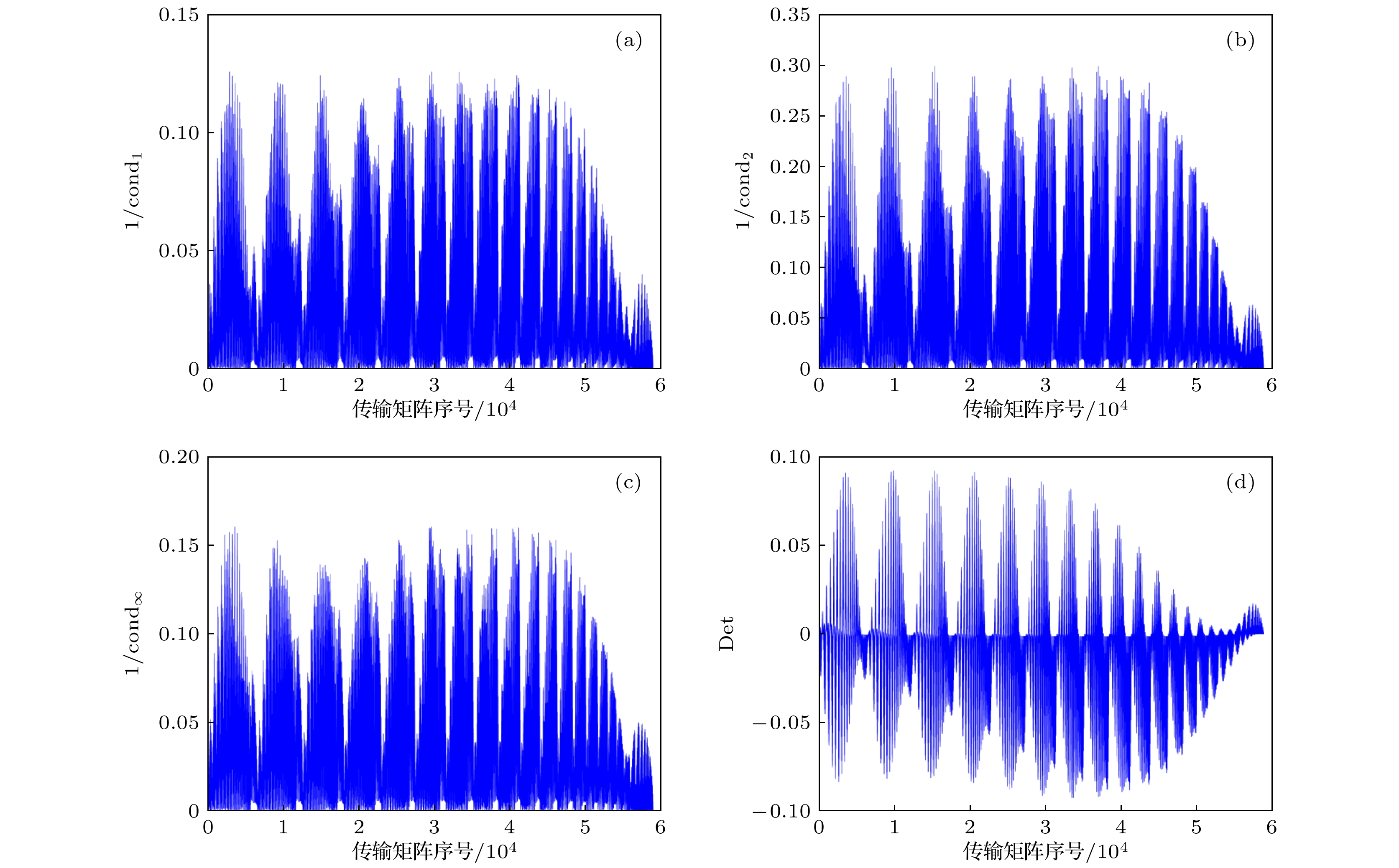
图 3
${{{M}}_{{\rm{tran}}}}$ 的$1/{\rm{Cond}}$ 与Det变化趋势 (a)$1/{\rm{Con}}{{\rm{d}}_1}$ 变化趋势; (b)$1/{\rm{Con}}{{\rm{d}}_2}$ 变化趋势; (c)$1/{\rm{Con}}{{\rm{d}}_\infty }$ 变化趋势; (d)$Det$ 变化趋势Figure 3. The change trend of
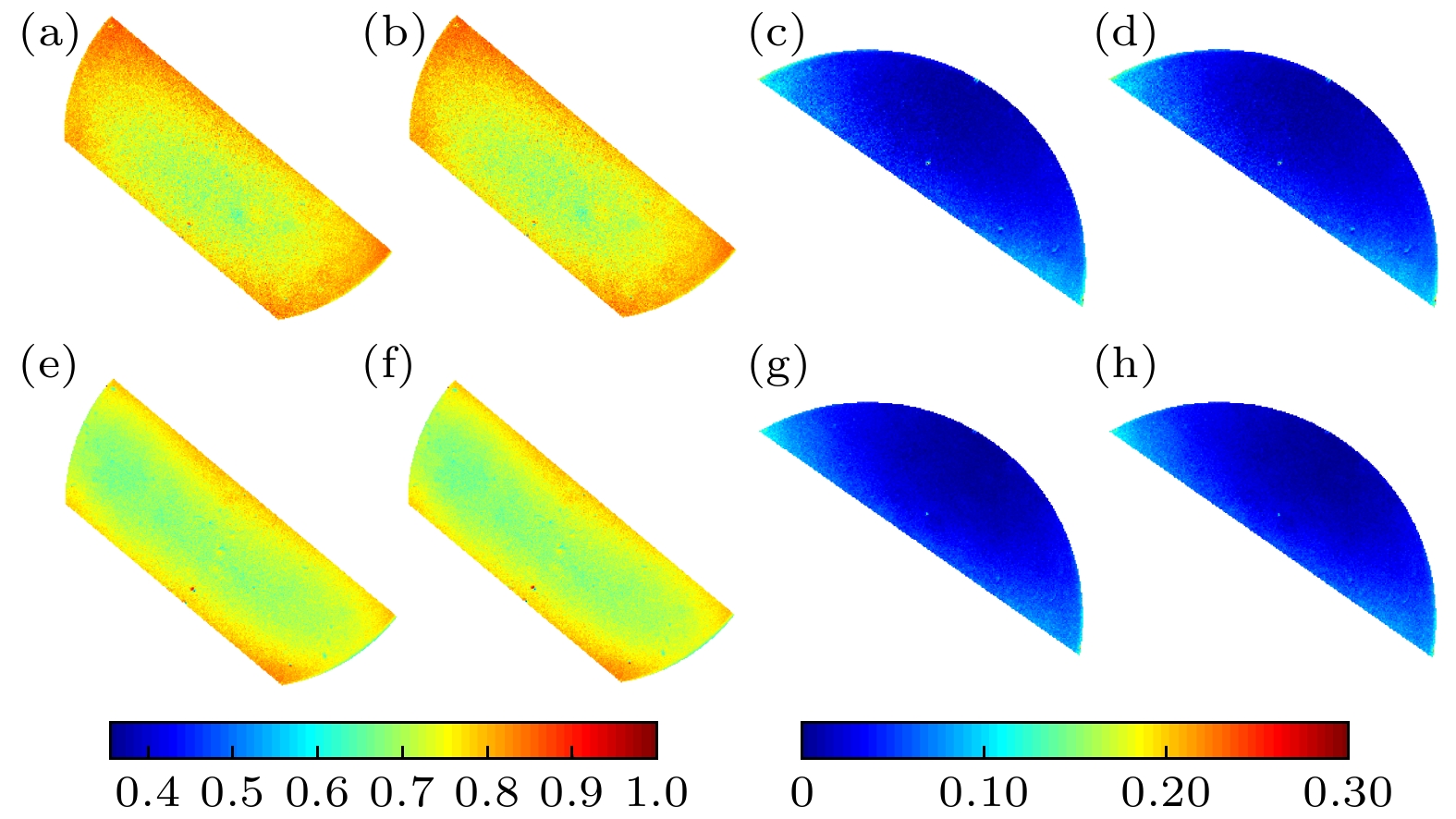
$1/{\rm{Cond}}$ and Det of the${{{M}}_{{\rm{tran}}}}$ : (a) Change trend of$1/{\rm{Con}}{{\rm{d}}_1}$ ; (b) change trend of$1/{\rm{Con}}{{\rm{d}}_2}$ ; (c) change trend of$1/{\rm{Con}}{{\rm{d}}_\infty }$ ; (d) change trend of Det.图 7 目标天空区域光强图与偏振模式分布结果 (a) 偏振光强图; (b) Aop; (c) Dop; (d) Dolp; (e) Docp; (f) I分量图; (g) Q分量图; (h) U分量图; (i) V分量图
Figure 7. The light intensity map and polarization mode distribution results of the target sky area: (a) Polarization intensity diagram; (b) Aop; (c) Dop; (d) Dolp; (e) Docp; (f) I component diagram; (g) Q component diagram; (h) U component diagram; (i) V component diagram.
表 1 最大Det、最小Cond与β对应表
Table 1. Corresponding table of maximum Det, minimum Cond and β.
条件数(Cond) 行列式(Det) 角度(β0, β1,
β2, β3)Cond1 8.6084 0.0923(最大) Det: (5°, 45°, 120°, 155°) Cond2 3.4864 Cond∞ 7.837 Cond1(最小) 7.9448 0.0814 Cond1: (0°, 30°, 115°, 150°) –0.0814 Cond1: (25°, 60°, 90°, 120°) Cond2 4.0092 — — Cond∞ 7.0859 — — Cond1 8.4653 — — Cond2(最小) 3.3381 –0.0919 Cond2: (35°, 70°, 100°, 135°) Cond∞ 7.791 — — Cond1 8.5767 — — Cond2 3.4563 — — Cond∞(最小) 6.2275 0.0911 Cond∞: (0°, 40°, 115°, 150°) 表 2 系统传输矩阵标定结果
Table 2. Calibration results of system transmission matrix
QWP旋转角度 m11 m12 m13 m14 5° 0.500 –0.44 –0.0775 0.225 10° 0.500 –0.377 –0.137 0.299 40° 0.500 0.0102 0.0577 0.497 45° 0.500 0.001 0.144 0.479 120° 0.500 –0.0574 –0.0994 –0.487 125° 0.500 –0.00975 –0.0268 –0.499 155° 0.500 –0.269 0.32 –0.274 160° 0.500 –0.352 0.295 –0.198 表 3 优化前后∆Aop数据离散度对比
Table 3. Comparisons of data dispersion of the ∆Aop before and after optimization.
Index 熵 均值 标准差 优化前 优化后 优化前 优化后 优化前 优化后 ∆Aop 1.996 1.7956 4.9553 4.2633 27.7036 24.709 表 4 优化前后BMP的数据离散度指标对比
Table 4. Comparisons of data dispersion index of BMP before and after optimization.
Index 熵 均值 标准差 优化前 优化后 优化前 优化后 优化前 优化后 $\Delta {\rm{Do}}{{\rm{p}}_{{\rm{BMP}}}}$ 2.6884 2.5550 0.7496 0.7252 0.0476 0.0359 $\Delta {\rm{Dol}}{{\rm{p}}_{{\rm{BMP}}}}$ 2.6933 2.5564 0.7508 0.7256 0.0481 0.0361 表 5 优化前后NZ数据离散度指标对比
Table 5. Comparisons of data dispersion index of NZ before and after optimization.
Index 熵 均值 标准差 Poa 优化前 优化后 优化前 优化后 优化前 优化后 优化前 优化后 $\Delta {\rm{Do}}{{\rm{p}}_{{\rm{NZ}}}}$ 1.5359 1.5141 0.0446 0.0413 0.0246 0.0222 31.9377 35.3431 $\Delta {\rm{Dol}}{{\rm{p}}_{{\rm{NZ}}}}$ 1.5285 1.5085 0.0441 0.0409 0.0245 0.0223 32.8158 35.9437 -
[1] 高隽, 范之国 2014 仿生偏振光导航方法 (北京: 科学出版社) 第2页
Gao J, Fan Z G 2014 Bionic polarized light navigation method (Beijing: Science Press) p2 (in Chinese)
[2] Wehner R 2003 J. Comp. Physiol. A 189 579
 Google Scholar
[3] Kraft P, Evangelista C, Dacke M, Labhart T, Srinivasan M V 2011 Philos. Trans. R. Soc. London, Ser. B 366 703
 Google Scholar
[4] Reppert S M, Zhu H, White R H 2014 Curr. Biol. 14 155
[5] Homberg U 2015 Front. Behav. Neurosci. 9 346
[6] Liang H J, Bai H Y, Liu N, Sui X B 2020 Math. Probl. Eng. 2020 1
[7] Li J S, Chu J K, Zhang R, Chen J H, Wang Y L 2020 Appl. Opt. 59 2955
 Google Scholar
[8] Dupeyroux J, Viollet S, Serres J R 2019 J. R. Soc. Interface 16 20180878
 Google Scholar
[9] 胡帅, 高太长, 李浩, 程天际, 刘磊, 黄威, 江诗阳 2016 65 014203
 Google Scholar
Hu S, Gao T C, Li H, Cheng T J, Liu L, Huang W, Jiang S Y 2016 Acta Phys. Sin. 65 014203
 Google Scholar
[10] 刘敬, 金伟其, 王霞, 鲁啸天, 温仁杰 2016 65 094201
 Google Scholar
Liu J, Jin W Q, Wang X, Lu X T, Wen R J 2016 Acta Phys. Sin. 65 094201
 Google Scholar
[11] 王晨光, 张楠, 李大林, 杨江涛, 王飞, 任建斌, 唐军, 刘俊, 薛晨阳 2015 光电工程 42 60
 Google Scholar
Wang C G, Zhang N, Li D L, Yang J T, Wang F, Ren J B, Tang J, Liu J, Xue C Y 2015 Opto-Electron. Eng. 42 60
 Google Scholar
[12] Horváth G, Barta A, Gál J, Suhai B, Haiman O 2002 Appl. Opt. 41 543
 Google Scholar
[13] Pust N J, Shaw J A 2006 Appl. Opt. 45 22
 Google Scholar
[14] 孙洁, 高隽, 怀宇, 毕冉, 范之国 2016 光电工程 43 45
 Google Scholar
Sun J, Gao J, Huai Y, Fan Z G 2016 Opto-Electron. Eng. 43 45
 Google Scholar
[15] 戴俊, 高隽, 范之国 2017 中国激光 44 184
Dai J, Gao J Fan Z G 2017 Chin. J. Las. 44 184
[16] Hsu W L, Myhre G, Balakrishnan K, Brock N, Ibn-Elhaj M, Pau S. 2014 Opt. Express 22 3063
 Google Scholar
[17] 张忠顺 2014 硕士学位论文 (合肥: 合肥工业大学)
Zhang Z S 2014 M. S. Thesis (Hefei: Hefei University of Technology) (in Chinese)
[18] 殷玉龙, 孙晓兵, 宋茂新, 陈卫, 陈斐楠 2019 68 024203
 Google Scholar
Yin Y L, Sun X B, Song M X, Chen W, Chen F N 2019 Acta Phys. Sin. 68 024203
 Google Scholar
[19] Kiyohara J, Ueno S, Kitai R, Kurokawa H, Makita M, Ichimoto K 2004 Ground-based Instrumentation for Astronomy (Glasgow: SPIE) p1778
[20] Anan T, Ichimoto K, Oi A, Kimura G, Nakatani Y, Ueno S 2012 Ground-based Instrumentation for Astronomy IV (Glasgow: SPIE) p84461C
[21] Isaacson E, Keller H B 2012 Analysis of numerical methods (Massachusetts: Courier) pp54−55
[22] Iniesta J C D T, Collados M 2000 Appl. Opt. 39 1637
 Google Scholar
[23] Worster S, Mouritsen H, Hore P J 2017 J. R. Soc. Interface 14 134
Catalog
Metrics
- Abstract views: 7797
- PDF Downloads: 157
- Cited By: 0


 DownLoad:


