-
自旋轨道转矩(spin-orbit torque, SOT)为超低功耗自旋电子器件提供新的实现方法, 在反铁磁材料体系中面内交换偏置场可辅助SOT磁化翻转, 同时利用电压调控磁各向异性(voltage-controlled magnetic anisotropy, VCMA)能有效降低翻转势垒, 从而实现无外场辅助的磁隧道结. 本文通过求解修正Landau-Lifshitz-Gilbert (LLG)方程, 建立反铁磁/铁磁/氧化物构成的无外场辅助自旋轨道矩的磁隧道结模型, 并对其磁化动力学过程进行分析. 以IrMn/CoFeB/MgO材料体系为例, 揭示了影响磁化翻转的因素, 包括交换偏置(exchange bias, EB)效应对临界翻转电流
$ {I_{{\text{SOT}}}} $ 的影响, VCMA效应和SOT类场转矩的影响机制; 分析了实际应用中磁隧道结制作工艺偏差的影响. 结果表明: EB效应与VCMA效应共同作用能极大降低临界翻转电流$ {I_{{\text{SOT}}}} $ , 从而实现完全无场开关切换; SOT类场转矩对磁化翻转起主导作用, 且一定条件下可实现器件在ps量级的无场翻转; 以及当氧化层厚度偏差$ {\gamma _{{\text{tf}}}} \leqslant 10\% $ 或自由层厚度偏差$ {\gamma _{{\text{tox}}}} \leqslant 13\% $ 时MTJ能实现有效切换. 基于反铁磁的无场辅助自旋轨道矩器件将为新一代超低功耗、超高速度和超高集成度器件和电路提供极具前景的解决方案.The effect of spin-orbit torque (SOT) provides a new method of implementing ultra-low power spintronic devices. The in-plane exchange bias (EB) field in antiferromagnetic material can effectively assist SOT magnetization switching. Meanwhile, the utilization of voltage-controlled magnetic anisotropy (VCMA) can effectively reduce the switching barrier. Taking advantage of the EB and VCMA effect, it is possible to realize SOT magnetic tunnel junctions without external field assistance. In this work, a spin-orbit torque magnetic tunnel junction model composed of antiferromagnetic/ferromagnetism/oxides without external magnetic field is developed by solving the modified Landau-Lifshitz-Gilbert (LLG) modular equation, and its magnetization dynamics is analyzed and studied. The effective fields in the model include the demagnetization field, thermal noise field, perpendicular magnetic anisotropy field with VCMA effect, and exchange bias field. Taking IrMn/CoFeB/MgO material system for example, the factors affecting the precession of magnetization are investigated, such as the effect of the exchange bias field, the VCMA effect and the mechanism of SOT field-like torque. Considering the practical applications, the effect of the deviation of the fabrication process of magnetic tunnel junctions is also analyzed. The simulation results demonstrate that the combined effect of$ {{\boldsymbol{H}}_{{\text{EB}}}} $ with VCMA effect can greatly reduce the critical ISOT, thus assisting and realizing the complete field-free magnetization reversal; the SOT field-like torque plays a dominant role in realizing the magnetization reversal, and by adjusting the ratio of the SOT field-like torque to the damping-like torque, field free switching can be realized in the device at the ps grade ; and the MTJ can realize effective switching when the deviation of oxide thickness$ {\gamma _{{\text{tf}}}} \leqslant 10{\text{%}} $ or the deviation of free layer thickness$ {\gamma _{{\text{tox}}}} \leqslant 13{\text{%}}$ . Spin-orbit torque devices based on the antiferromagnetic without external magnetic field will provide highly promising solutions for a new-generation ultra-low power, ultra-high speed, and ultra-high integration devices and circuits.-
Keywords:
- spin-orbit torque magnetic tunnel junction /
- voltage-controlled magnetic anisotropy /
- exchange bias /
- process deviation
[1] Bhatti S, Sbiaa R, Hirohata A, Ohno H, Fukami S, Piramanayagam S N 2017 Mater. Today 20 530
 Google Scholar
[2] Slonczewski J C 1996 J. Magn. Magn. Mater. 159 L1
 Google Scholar
[3] Berger L 1992 J. Appl. Phys. 71 2721
 Google Scholar
[4] Wang Z H, Zhou H C, Wang M X, Cai W L, Zhu D Q, Klein J O, Zhao W S 2019 IEEE Electr. Device L. 40 726
 Google Scholar
[5] Fong B, Fong A C M, Hong G Y, Ryu H 2005 IEEE Antenn. Wirel. Pr. 4 20
 Google Scholar
[6] Manchon A, Železný J, Miron I M, Jungwirth T, Sinova J, Thiaville A, Garrello K, Gambardella P 2019 Rev. Mod. Phys. 91 035004
 Google Scholar
[7] 粟傈, 童良乐, 李晴, 王可欣 2023 电子元件与材料 42 127
 Google Scholar
Su L, Tong L L, Li Q, Wang K X 2023 Electr. Comp. Mater. 42 127
 Google Scholar
[8] Zhou J, Shu X Y, Liu Y H, Wang X, Lin W N, Chen S H, Liu L, Xie Q D, Hong T, Yang P, Yan B H, Han X F, Chen J S 2020 Phys. Rev. B 101 184403
 Google Scholar
[9] Park B G, Wunderlich J, Martí X, Holý V, Kurosaki Y, Yamada M, Yamamoto H, Nishide A, Hayakawa J, Takahashi H, Shick A B, Jungwirth T 2011 Nat. Mater. 10 347
 Google Scholar
[10] Lau Y C, Betto D, Rode K, Coey, J M D, Stamenov P 2016 Nat. Nanotechnol. 11 758
 Google Scholar
[11] Liu Y, Zhou B, Zhu J G 2019 Sci. Rep. UK 9 325
 Google Scholar
[12] Wang M X, Zhou J, Xu X G, Zhang T Z, Zhu Z Q, Guo Z X, Deng Y B, Yang M, Meng K K, He B, Li J L, Yu G Q, Zhu T, Li A, Han X D, Jiang Y 2023 Nat. Commun. 14 2871
 Google Scholar
[13] Lin P H, Yang B Y, Tsai M H, Chen P C, Huang K F, Lin H H, La C H 2019 Nat. Mater. 18 335
 Google Scholar
[14] Kim H J, Je S G, Jung D H, Lee K S, Hong J I 2019 Appl. Phys. Lett. 115 022401
 Google Scholar
[15] Amiri P K, Alzate J G, Cai X Q, Ebrahim F, Hu Q, Wong K, Grèzes C, Lee H, Yu G Q, Li X, Akyol M, Shao Q M, Katine J A, Langer J, Ocker B, Wang K L 2015 IEEE T. Magn. 51 1
 Google Scholar
[16] Wang W G, Li M, Hageman S, Chien C L 2012 Nat. Mater. 11 64
 Google Scholar
[17] Alzate J G, Amiri P K, Upadhyaya P, Cherepov S S, Zhu J, Lewis M, Dorrance R, Katine J A, Langer J, Galatsis K, Markovic D, Krivorotov I, Wang K L 2012 IEEE IEDM San Francisco, CA, USA, December 10–13, 1999 p29.5. 1
[18] Zhang H, Kang W, Wang L, Wang K L, Zhao W 2017 IEEE T Electron. Dev. 64 4295
 Google Scholar
[19] Inokuchi T, Yoda H, Kato Y, Shimizu M, Shirotori S, Shimomura N, Koi K, Kamiguchi Y, Sugiyama H, Oikawa S, Ikegami K, Ishikawa M, Altansargai B, Tiwari A, Ohsawa Y, Saito Y, Kurobe A 2017 Appl. Phys. Lett. 110 1
[20] Lee K, Kan J, Kang S H 2017 US Patent 9 589 619
[21] Zhang K L, Zhang D M, Wang C Z, Zeng L, Wang Y, Zhao W S 2020 IEEE Access. 8 50792
 Google Scholar
[22] Wang Y, Cai H, Naviner L A B, Zhao X X, Zhang Y, Slimani M, Klein J O, Zhao W S 2016 Microelectron. Reliab. 64 26
 Google Scholar
[23] Meng H, Lum W H, Sbiaa R, Lua S Y H, Tan H K 2011 J. Appl. Phys. 110 033904
 Google Scholar
[24] Jeong J, Endoh T 2017 Jpn. J. Appl. Phys. 56 04CE09
 Google Scholar
[25] Wang M X, Cai W L, Zhu D Q, Wang Z H, Kan J, Zhao Z Y, Cao K H, Wang Z L, Zhang Y G, Zhang T R, Park C, Wang J P, Fert A, Zhao W S 2018 Nat. Electron. 1 582
 Google Scholar
[26] Kazemi M, Rowlands G E, Ipek E, Buhrman R A, Friedman E G 2016 IEEE T. Electron. Dev. 63 848
 Google Scholar
[27] Lee H, Lee A, Wang S D, Ebrahimi F, Gupta P, Amiri P K, Wang K L 2018 IEEE T. Magn. 54 1
 Google Scholar
[28] Kang W, Ran Y, Zhang Y G, Lü W F, Zhao W S 2017 IEEE T. Nanotechnol. 16 387
 Google Scholar
[29] 王日兴, 曾逸涵, 赵婧莉, 李连, 肖运昌 2023 72 087202
 Google Scholar
Wang R X, Zeng Y H, Zhao J L, Li L, Xiao Y C 2023 Acta Phys. Sin. 72 087202
 Google Scholar
[30] Legrand W, Ramaswamy R, Mishra R, Yang H 2015 Phys. Rev. Appl. 3 064012
 Google Scholar
[31] 金冬月, 陈虎, 王佑, 张万荣, 那伟聪, 郭斌, 吴玲, 杨绍萌, 孙晟 2020 69 198502
 Google Scholar
Jin D Y, Chen H, Wang Y, Zhang W R, Na W C, Guo B, Wu L, Yang S M, Sun S 2020 Acta Phys. Sin. 69 198502
 Google Scholar
[32] 金冬月, 曹路明, 王佑, 贾晓雪, 潘永安, 周钰鑫, 雷鑫, 刘圆圆, 杨滢齐, 张万荣 2022 71 107501
 Google Scholar
Jin D Y, Cao L M, Wang Y, Jia X X, Pan Y A, Zhou Y X, Lei X, Liu Y Y, Yang Y Q, Zhang W R 2022 Acta Phys. Sin. 71 107501
 Google Scholar
[33] Rata A D, Braak H, Bürgler D E, Schneider C M 2007 Appl. Phys. Lett. 90 162512
 Google Scholar
[34] Gajek M, Nowak J J, Sun J Z, Trouilloud P L, O’ sullivan E J, Abraham D W, Gaidis M C, Hu G, Brown S, Zhu Y, Robertazzi R P, Gallagher W J, Worledge D C 2012 Appl. Phys. Lett. 100 132408
 Google Scholar
-
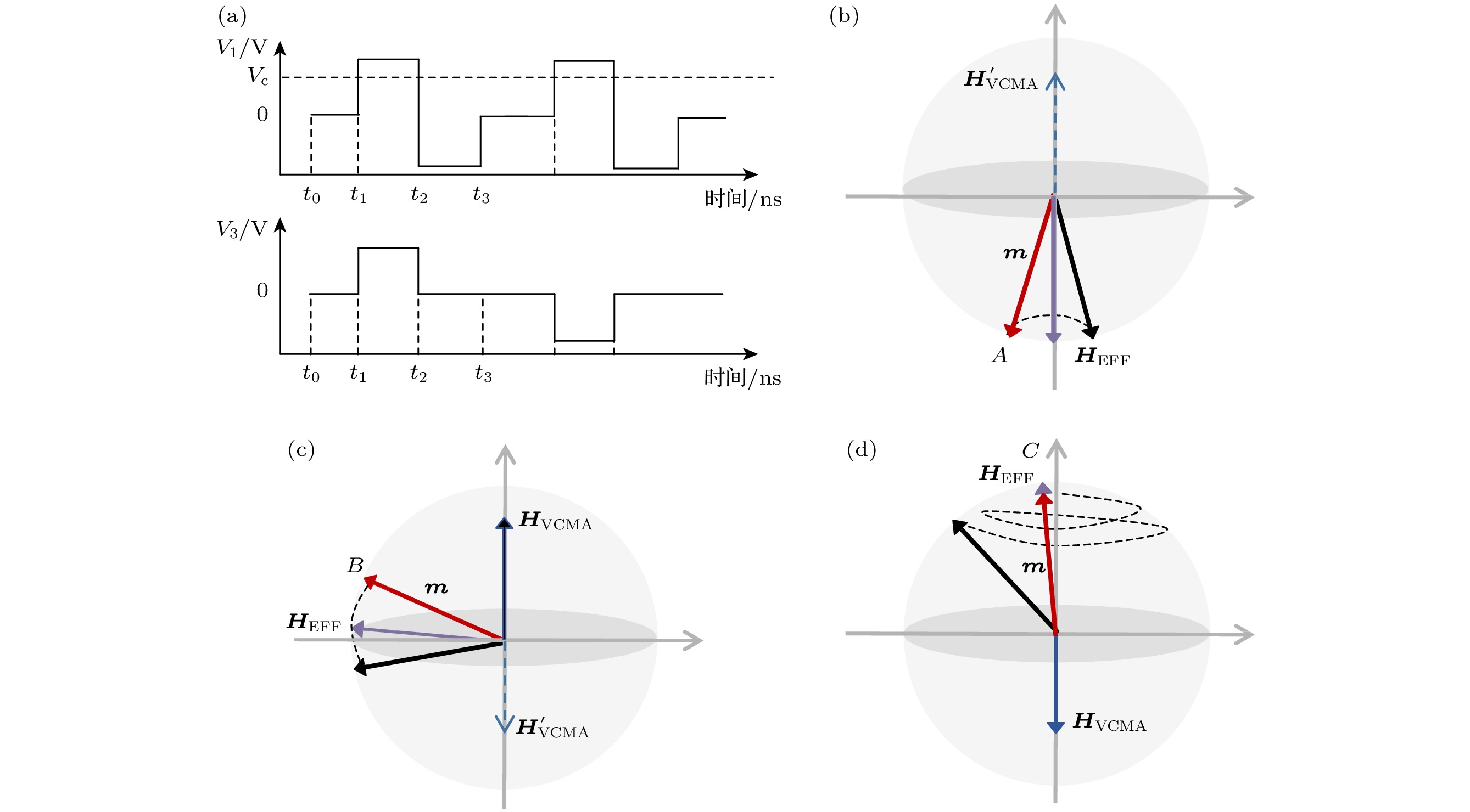
图 2 (a) AP态切换到P态器件外加电压随时间的变化; (b)
$ {t}_{0}<t\leqslant {t}_{1} $ 磁化翻转示意图; (c)$ {t}_{1}<t\leqslant {t}_{2} $ 磁化翻转示意图; (d)$ {t}_{2}< $ $ t\leqslant {t}_{3} $ 磁化翻转示意图Fig. 2. (a) Change of the applied voltage of a device from AP state to P state with time; (b) schematic diagram of magnetization reversal during
$ {t}_{0}<t\leqslant {t}_{1} $ ; (c) schematic diagram of magnetization reversal during$ {t}_{1}<t\leqslant {t}_{2} $ ; (c) schematic diagram of magnetization reversal during$ {t}_{2}<t\leqslant {t}_{3} $ 图 3 (a) AP状态下
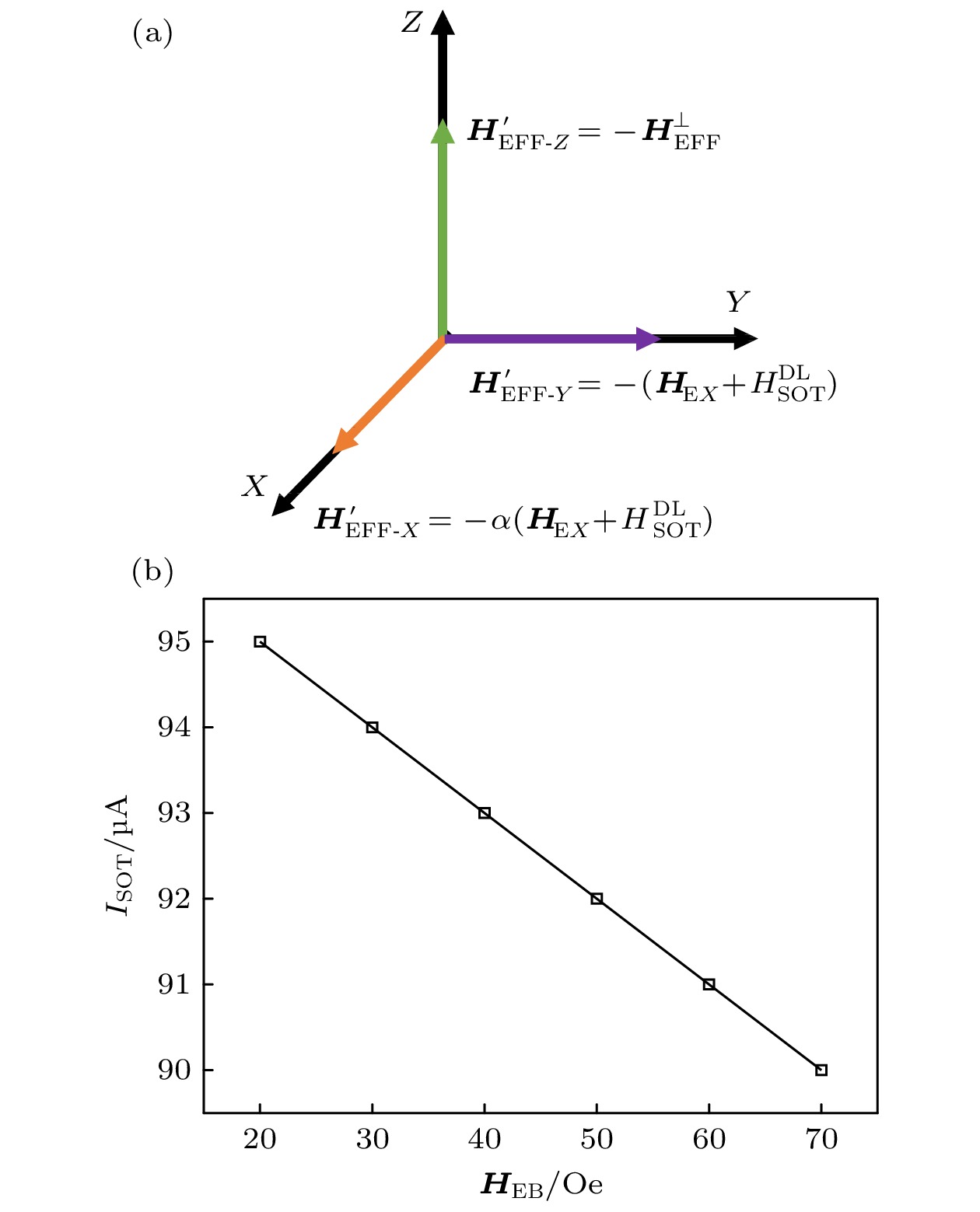
$ {\boldsymbol{H}}_{{\text{EFF}}}' $ 在坐标轴的分量; (b)不同$ {{\boldsymbol{H}}_{{\text{EB}}}} $ 下的临界$ {I_{{\text{SOT}}}} $ Fig. 3. (a) Component of
$ {\boldsymbol{H}}_{{\text{EFF}}}' $ on the coordinate axis in AP state; (b) critical$ {I_{{\text{SOT}}}} $ under different$ {{\boldsymbol{H}}}_{{\text{EB}}} $ .图 5 (a) VCSOT-MTJ在不同
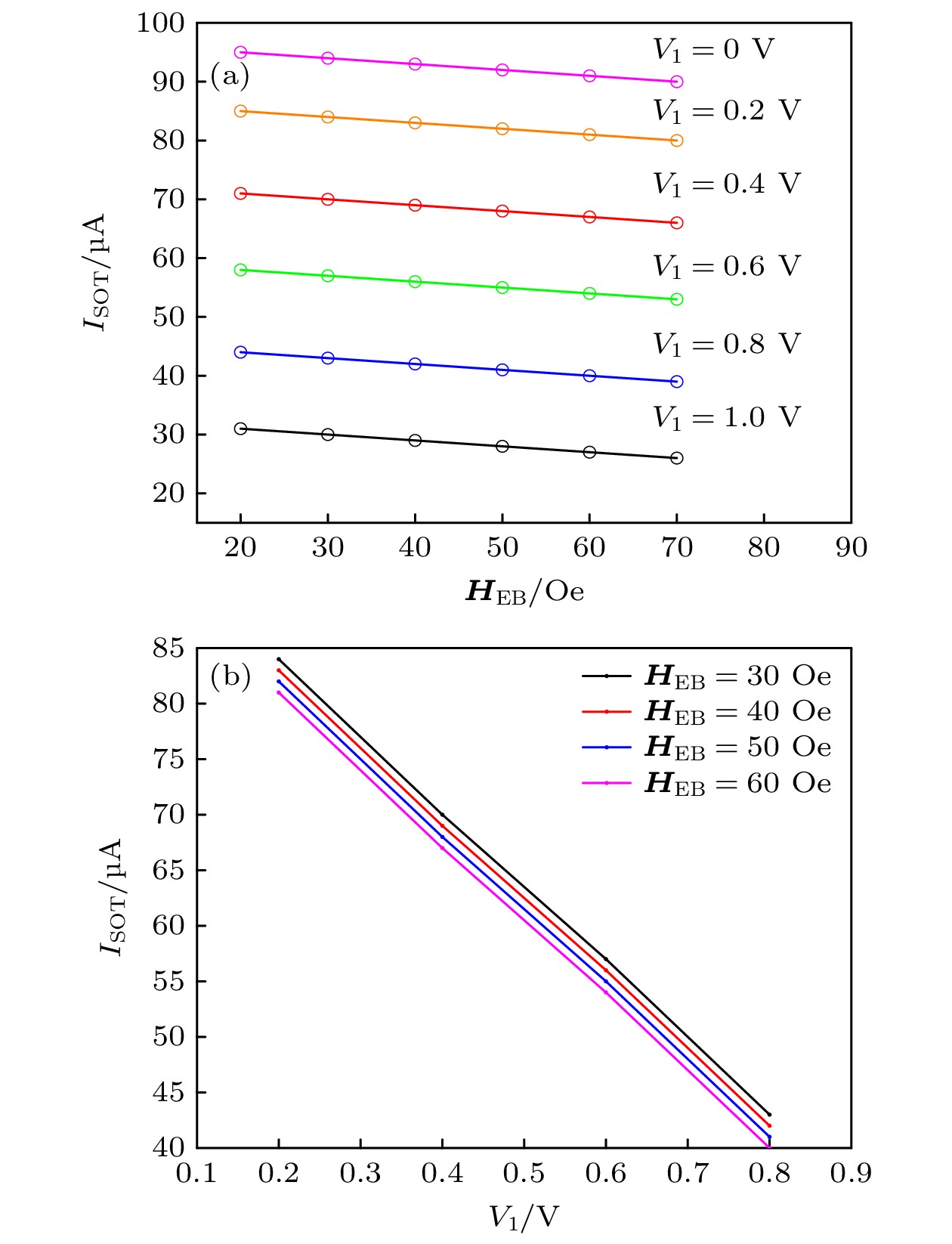
$ {{\boldsymbol{H}}_{{\text{EB}}}} $ 下改变V1的临界$ {I_{{\text{SOT}}}} $ ; (b)截取部分临界$ {I_{{\text{SOT}}}} $ 下降趋势Fig. 5. (a) Critical
$ {I_{{\text{SOT}}}} $ of VCSOT-MTJ under different$ {{\boldsymbol{H}}_{{\text{EB}}}} $ and V1; (b) intercepted part of the critical$ {I_{{\text{SOT}}}} $ downward trend.表 1 VCSOT-MTJ模型部分参数
Table 1. Partial parameters of the VCSOT-MTJ model.
参数 符号 默认值 饱和磁化强度 $ {M_{\text{s}}} $ $ 0.625 \times {10^6}~{\rm A}{\text{/m}} $ 垂直磁各向异性系数 $ {K_{\text{i}}} $ $ 3.2 \times {10^{{{ - }}4}}~{\text{J/}}{{\text{m}}^{2}} $ MTJ直径 $ D $ 50 nm VCMA系数 $ \beta $ $ 60~ {\text{fJ/(V}}{\cdot}{\text{m)}} $ 自旋极化率 $ P $ $ 0.58 $ 温度 $ T $ 300 K 氧化层厚度值 $ {t_{{\text{ox}}}} $ 1.4 nm 自由层厚度值 $ {t_{\text{f}}} $ 1.1 nm 自旋霍尔角 $ {\theta _{{\text{SH}}}} $ $ 0.25 $ $ H_{{\text{STT}}}^{{\text{FL}}} $与$ H_{{\text{STT}}}^{{\text{DL}}} $比值 $ {\xi _1} $ $ 0 $ $ H_{{\text{SOT}}}^{{\text{FL}}} $与$ H_{{\text{SOT}}}^{{\text{DL}}} $比值 $ {\xi _2} $ $ 0 $ AFM材料长, 宽, 高 $ {L_{{\text{AFM}}}}, {W_{{\text{AFM}}}}, {T_{{\text{AFM}}}} $ $ 60\,{\text{nm,}}\;{50}\,{\text{nm,}}\;{3}\,{\text{nm}} $ AFM电阻率 $ {\rho _{{\text{AFM}}}} $ $ 2.78 \times {10^{{{-}}6}}\;\Omega{\cdot}{\text{m}} $ -
[1] Bhatti S, Sbiaa R, Hirohata A, Ohno H, Fukami S, Piramanayagam S N 2017 Mater. Today 20 530
 Google Scholar
[2] Slonczewski J C 1996 J. Magn. Magn. Mater. 159 L1
 Google Scholar
[3] Berger L 1992 J. Appl. Phys. 71 2721
 Google Scholar
[4] Wang Z H, Zhou H C, Wang M X, Cai W L, Zhu D Q, Klein J O, Zhao W S 2019 IEEE Electr. Device L. 40 726
 Google Scholar
[5] Fong B, Fong A C M, Hong G Y, Ryu H 2005 IEEE Antenn. Wirel. Pr. 4 20
 Google Scholar
[6] Manchon A, Železný J, Miron I M, Jungwirth T, Sinova J, Thiaville A, Garrello K, Gambardella P 2019 Rev. Mod. Phys. 91 035004
 Google Scholar
[7] 粟傈, 童良乐, 李晴, 王可欣 2023 电子元件与材料 42 127
 Google Scholar
Su L, Tong L L, Li Q, Wang K X 2023 Electr. Comp. Mater. 42 127
 Google Scholar
[8] Zhou J, Shu X Y, Liu Y H, Wang X, Lin W N, Chen S H, Liu L, Xie Q D, Hong T, Yang P, Yan B H, Han X F, Chen J S 2020 Phys. Rev. B 101 184403
 Google Scholar
[9] Park B G, Wunderlich J, Martí X, Holý V, Kurosaki Y, Yamada M, Yamamoto H, Nishide A, Hayakawa J, Takahashi H, Shick A B, Jungwirth T 2011 Nat. Mater. 10 347
 Google Scholar
[10] Lau Y C, Betto D, Rode K, Coey, J M D, Stamenov P 2016 Nat. Nanotechnol. 11 758
 Google Scholar
[11] Liu Y, Zhou B, Zhu J G 2019 Sci. Rep. UK 9 325
 Google Scholar
[12] Wang M X, Zhou J, Xu X G, Zhang T Z, Zhu Z Q, Guo Z X, Deng Y B, Yang M, Meng K K, He B, Li J L, Yu G Q, Zhu T, Li A, Han X D, Jiang Y 2023 Nat. Commun. 14 2871
 Google Scholar
[13] Lin P H, Yang B Y, Tsai M H, Chen P C, Huang K F, Lin H H, La C H 2019 Nat. Mater. 18 335
 Google Scholar
[14] Kim H J, Je S G, Jung D H, Lee K S, Hong J I 2019 Appl. Phys. Lett. 115 022401
 Google Scholar
[15] Amiri P K, Alzate J G, Cai X Q, Ebrahim F, Hu Q, Wong K, Grèzes C, Lee H, Yu G Q, Li X, Akyol M, Shao Q M, Katine J A, Langer J, Ocker B, Wang K L 2015 IEEE T. Magn. 51 1
 Google Scholar
[16] Wang W G, Li M, Hageman S, Chien C L 2012 Nat. Mater. 11 64
 Google Scholar
[17] Alzate J G, Amiri P K, Upadhyaya P, Cherepov S S, Zhu J, Lewis M, Dorrance R, Katine J A, Langer J, Galatsis K, Markovic D, Krivorotov I, Wang K L 2012 IEEE IEDM San Francisco, CA, USA, December 10–13, 1999 p29.5. 1
[18] Zhang H, Kang W, Wang L, Wang K L, Zhao W 2017 IEEE T Electron. Dev. 64 4295
 Google Scholar
[19] Inokuchi T, Yoda H, Kato Y, Shimizu M, Shirotori S, Shimomura N, Koi K, Kamiguchi Y, Sugiyama H, Oikawa S, Ikegami K, Ishikawa M, Altansargai B, Tiwari A, Ohsawa Y, Saito Y, Kurobe A 2017 Appl. Phys. Lett. 110 1
[20] Lee K, Kan J, Kang S H 2017 US Patent 9 589 619
[21] Zhang K L, Zhang D M, Wang C Z, Zeng L, Wang Y, Zhao W S 2020 IEEE Access. 8 50792
 Google Scholar
[22] Wang Y, Cai H, Naviner L A B, Zhao X X, Zhang Y, Slimani M, Klein J O, Zhao W S 2016 Microelectron. Reliab. 64 26
 Google Scholar
[23] Meng H, Lum W H, Sbiaa R, Lua S Y H, Tan H K 2011 J. Appl. Phys. 110 033904
 Google Scholar
[24] Jeong J, Endoh T 2017 Jpn. J. Appl. Phys. 56 04CE09
 Google Scholar
[25] Wang M X, Cai W L, Zhu D Q, Wang Z H, Kan J, Zhao Z Y, Cao K H, Wang Z L, Zhang Y G, Zhang T R, Park C, Wang J P, Fert A, Zhao W S 2018 Nat. Electron. 1 582
 Google Scholar
[26] Kazemi M, Rowlands G E, Ipek E, Buhrman R A, Friedman E G 2016 IEEE T. Electron. Dev. 63 848
 Google Scholar
[27] Lee H, Lee A, Wang S D, Ebrahimi F, Gupta P, Amiri P K, Wang K L 2018 IEEE T. Magn. 54 1
 Google Scholar
[28] Kang W, Ran Y, Zhang Y G, Lü W F, Zhao W S 2017 IEEE T. Nanotechnol. 16 387
 Google Scholar
[29] 王日兴, 曾逸涵, 赵婧莉, 李连, 肖运昌 2023 72 087202
 Google Scholar
Wang R X, Zeng Y H, Zhao J L, Li L, Xiao Y C 2023 Acta Phys. Sin. 72 087202
 Google Scholar
[30] Legrand W, Ramaswamy R, Mishra R, Yang H 2015 Phys. Rev. Appl. 3 064012
 Google Scholar
[31] 金冬月, 陈虎, 王佑, 张万荣, 那伟聪, 郭斌, 吴玲, 杨绍萌, 孙晟 2020 69 198502
 Google Scholar
Jin D Y, Chen H, Wang Y, Zhang W R, Na W C, Guo B, Wu L, Yang S M, Sun S 2020 Acta Phys. Sin. 69 198502
 Google Scholar
[32] 金冬月, 曹路明, 王佑, 贾晓雪, 潘永安, 周钰鑫, 雷鑫, 刘圆圆, 杨滢齐, 张万荣 2022 71 107501
 Google Scholar
Jin D Y, Cao L M, Wang Y, Jia X X, Pan Y A, Zhou Y X, Lei X, Liu Y Y, Yang Y Q, Zhang W R 2022 Acta Phys. Sin. 71 107501
 Google Scholar
[33] Rata A D, Braak H, Bürgler D E, Schneider C M 2007 Appl. Phys. Lett. 90 162512
 Google Scholar
[34] Gajek M, Nowak J J, Sun J Z, Trouilloud P L, O’ sullivan E J, Abraham D W, Gaidis M C, Hu G, Brown S, Zhu Y, Robertazzi R P, Gallagher W J, Worledge D C 2012 Appl. Phys. Lett. 100 132408
 Google Scholar
计量
- 文章访问数: 6831
- PDF下载量: 135
- 被引次数: 0


 下载:
下载:


