-
超磁致伸缩材料的磁滞模型随着激励幅值、偏磁情况、激励频率的变化模型参数也会发生变化, 现有的磁滞模型无法预测三种外部条件同时变化所带来的影响. 本文通过传统Jiles-Atherton (J-A)动态模型解释磁滞损耗机理, 根据运行条件和材料特性建立关系式来反映外界条件变化. 针对J-A模型建立与激励幅值相关的关系式, 针对剩余损耗建立起剩余损耗系数与激励幅值和偏磁情况的关系式, 同时利用分数阶对系统的涡流损耗重新进行定义, 从而得到修正后的磁滞模型. 文中利用遗传算法对不同运行条件下的试验数据进行模型参数辨识, 根据模型参数以及运行条件得到相应的修正系数. 通过模型的仿真情况, 验证了修正后模型的精度, 分析了涡流和剩余损耗的影响因素以及对模型预测的影响; 通过对磁滞模型进行评估, 对比了磁滞曲线与磁滞损耗的误差情况. 结果表明, 修正后的模型能够对不同的激励进行高精度预测, 低频时忽略动态损耗会造成较大误差, 且涡流和剩余损耗对磁滞模型精度具有较大影响, 在对具体磁滞情况进行分析时利用磁滞曲线进行评估更为准确.
-
关键词:
- 超磁致伸缩材料 /
- Jiles-Atherton动态模型 /
- 涡流损耗 /
- 剩余损耗
The hysteresis model of giant magnetostrictive materials (GMMs) changes with model parameters: the excitation amplitude, bias condition and excitation frequency. The existing hysteresis model is unable to predict the effects of simultaneous changes in the three external conditions. In this paper, the hysteresis loss mechanism is explained by using the traditional Jiles-Atherton (J-A) dynamic model, and the relation equation is established according to the operating conditions and material properties to respond to the changes of external conditions. For the J-A model, the relationship equation related to the excitation amplitude is established, and the relationship equation relating the residual loss coefficient to the excitation amplitude and the bias condition is established for the residual loss, while the eddy current loss of the system is redefined by using the fractional order to obtain the modified hysteresis model. In the paper, the genetic algorithm is used to identify the model parameters of the test data under different operating conditions, and the corresponding correction coefficients are obtained according to the model parameters and the operating conditions. The accuracy of the modified model is verified by simulating the model and analyzing the influences of eddy currents and residual losses and their effects on the model predictions. The hysteresis model is evaluated to compare the hysteresis curves with the hysteresis losses in terms of errors. The results show that the modified model is capable of predicting various excitations with high accuracy, and that neglecting dynamic losses at low frequencies results in large errors. If the model order of the eddy current loss is smaller than the actual order of the material, the predicted hysteresis curve will be contracted inward and the predicted eddy current loss will be small; on the contrary, the predicted hysteresis curve will be expanded outward and the predicted eddy current loss will be large, and with the increase of the excitation frequency, both cases will cause the prediction error to become larger and larger. When the bias magnetic field is zero, the residual loss coefficient is unchanged; when the bias magnetic field is kept constant, the excitation amplitude increases and the residual loss coefficient decreases; when the excitation amplitude is unchanged, the bias magnetic field increases and the residual loss coefficient also increases. When both the bias magnetic field and the excitation amplitude change at the same time, it is necessary to conduct an actual analysis of their corresponding residual loss coefficients. Using hysteresis curves to evaluate hysteresis is more accurate.-
Keywords:
- giant magnetostrictive materials /
- Jiles-Atherton dynamic model /
- eddy current loss /
- residual loss
[1] Yang Z J, Li J H, Zhou Z G, Gong J X, Bao X Q, Gao X X 2022 Metals 12 341
 Google Scholar
[2] Yamaura S, Nakajima T, Kamata Y, Sasaki T, Sekiguchi T 2020 J. Magn. Magn. Mater. 514 167260
 Google Scholar
[3] Yu C F, Wu G, Wang Y, Xiao Z H, Duan Y Y, Chen Z 2022 IEEE Access 10 43501
 Google Scholar
[4] Li Y S 2023 Shock Vib. 2023 7379276
 Google Scholar
[5] Liu Y G, Gao X H, Li Y L 2016 Sensor. Actuat. APhys. 250 7
 Google Scholar
[6] Sablik M J, Jiles D C 1988 J. Appl. Phys. 64 5402
 Google Scholar
[7] Unniachanparambil G M, Kulkarni S V 2019 IET Electr. Power App. 13 2090
 Google Scholar
[8] 王洋, 刘志珍 2017 中国电机工程学报 37 313
 Google Scholar
Wang Y, Liu Z Z 2017 Proc. CSEE 37 313
 Google Scholar
[9] 刘任, 李琳 2019 高电压技术 45 4062
 Google Scholar
Liu R, Li L 2019 High Volt. Eng. 45 4062
 Google Scholar
[10] 澹台乐琰, 韩肖清, 王磊, 袁铁江 2020 电网技术 44 122
 Google Scholar
Tantai L Y, Han X Q, Wang L, Yuan T J 2020 Power Syst. Technol. 44 122
 Google Scholar
[11] 刘任, 顾朝阳, 孙江东, 唐波 2024 中国电机工程学报 1 1
 Google Scholar
Liu R, Gu C Y, Sun J D, Tang B 2024 Proc. CSEE 1 1
 Google Scholar
[12] Zhang B, Gupta B, Ducharne B, Sébald G, Uchimoto T 2018 IEEE T. Mang. 54 7301605
 Google Scholar
[13] Zhang B, Gupta B, Ducharne B, Sébald G, Uchimoto T 2018 IEEE T. Mang. 54 6100204
 Google Scholar
[14] Liu R, Li L 2021 IEEE T. Power Electr. 36 2009
 Google Scholar
[15] Hamimid M, Mimoune S M, Feliachi M 2012 Physica B 407 2438
 Google Scholar
[16] Liu Y G, Gao X H, Chen C X 2016 Math. Probl. Eng. 2016 2609069
 Google Scholar
[17] Meng A H, Zhu J M, Kong M, He H L 2013 IEEE T. Mang. 49 552
 Google Scholar
[18] 陈彬, 秦小彬, 唐波, 刘任, 张建功, 万妮娜 2022 中国电机工程学报 42 4590
 Google Scholar
Chen B, Qin X B, Tang B, Liu R, Zhang J G, Wan N N 2022 Proc. CSEE 42 4590
 Google Scholar
[19] Li Y, Zhu L H, Zhu J G 2018 IEEE T. Mang. 54 1300105
 Google Scholar
[20] Baghel A P S, Kulkarni S V 2014 IEEE T. Mang. 50 7009004
 Google Scholar
[21] Jumarie G 2009 Appl. Math. Lett. 22 1659
 Google Scholar
[22] Wang Y, Liu Z Z 2016 IEEE T Appl. Supercon. 26 0608905
 Google Scholar
[23] Liu R, Li L 2019 IEEE T. Mang. 55 7501404
 Google Scholar
[24] Wei Y F, Yang X, Chen Y K, Zheng H B, Su L L 2022 IEEE T. Mang. 58 7300909
 Google Scholar
[25] Zhu Y C, Yang X L, Wereley N M 2016 Smart Mater. Struct. 25 085030
 Google Scholar
[26] Du R Y, Robertson P 2015 UKSim (Cambridge: Emmanuel Coll) p432
-
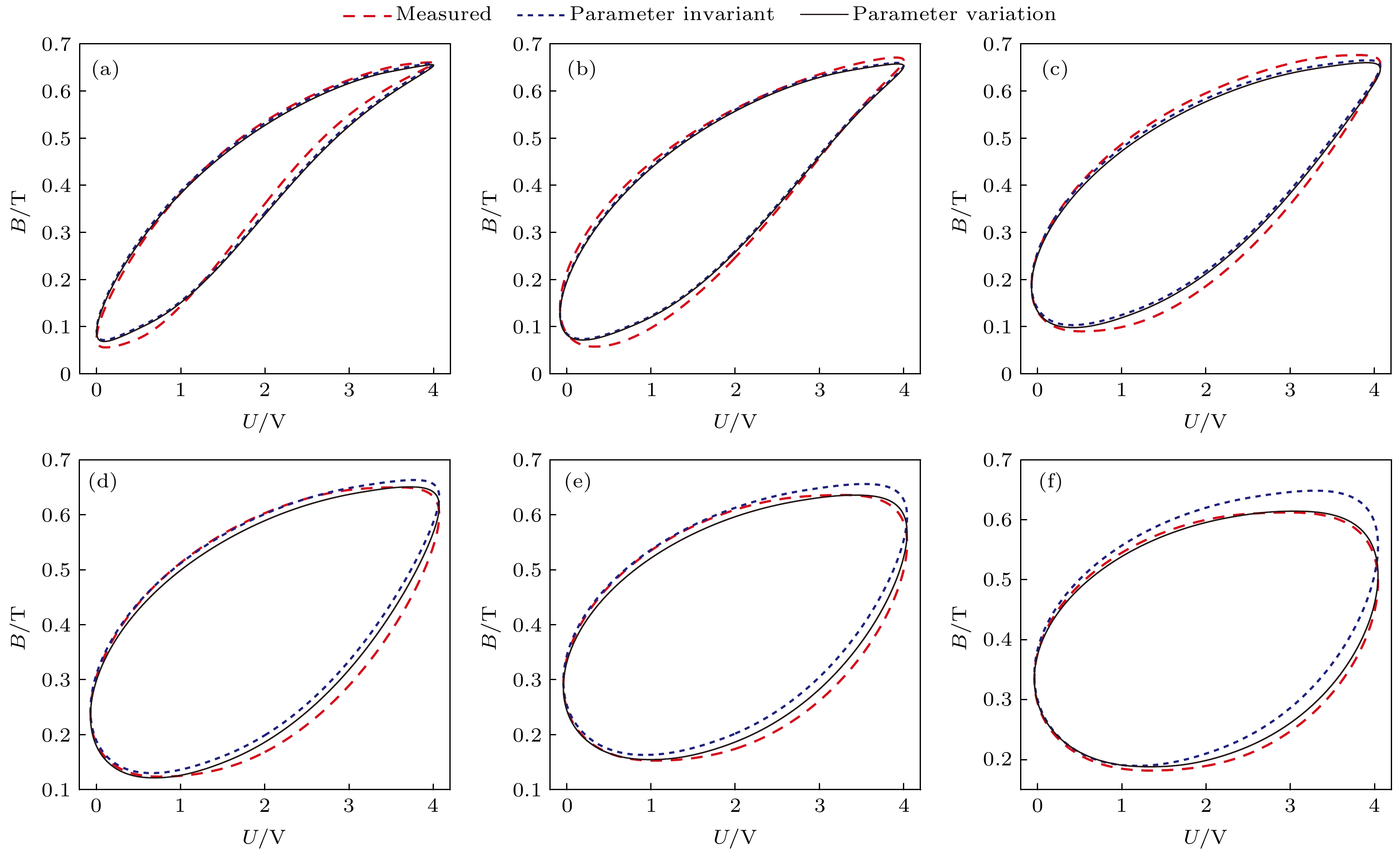
图 7 0—4 V激励下磁感应强度随频率变化动态特性 (a) f = 100 Hz; (b) f = 200 Hz; (c) f = 300 Hz; (d) f = 400 Hz; (e) f = 500 Hz; (f) f = 600 Hz
Fig. 7. Dynamic characterization of magnetic inductance with frequency under 0–4 V excitation. (a) f = 100 Hz; (b) f = 200 Hz; (c) f = 300 Hz; (d) f = 400 Hz; (e) f = 500 Hz; (f) f = 600 Hz
表 1 GMA系统主要相关参数
Table 1. GMA system main relevant parameters.
名称 符号 单位 数值 GMM棒长 l m 0.08 GMM直径 D m 0.0128 GMM质量 m2 kg 0.12 GMM棒相对磁导率 μr — 9 GMM棒电阻率 ρ Ω·m 6×10⁻⁷ 激励线圈匝数 N — 1000 真空磁导率 μ0 H·m–1 4π×10–7 漏磁系数 kg — 1.1 饱和磁滞伸缩系数 λs 10–6 1100 表 2 修改后的模型辨识参数
Table 2. Modified model parameter identification.
系数 数值 系数 数值 系数 数值 α 0.01812 λα –0.613 kcl 8.533 c 0.3899 λc 2.393 ka 21.03 k 4407 λk –0.933 w1 9.35×10⁸ a 16179 λa 0.7 w2 3.97 Ms 695000 p 1.07 w3 –29.35 表 3 不同激励下的磁感应强度
Table 3. Magnetic induction at various excitations.
U/V f/Hz Bmin/T Bmax/T Bp/T Bd/T 0—5 20 0.066 0.7038 0.3189 0.3849 0—4 20 0.0504 0.669 0.3093 0.3597 0—4 100 0.056 0.661 0.3025 0.3585 0—4 200 0.059 0.66 0.3005 0.3595 0—4 300 0.09 0.676 0.293 0.383 0—4 400 0.124 0.65 0.263 0.387 0—4 500 0.153 0.636 0.2415 0.3945 0—4 600 0.182 0.612 0.215 0.397 0—3 20 0.0499 0.5686 0.25935 0.30925 0—3 200 0.0559 0.5832 0.26365 0.31955 0—3 400 0.107 0.536 0.2145 0.3215 0—3 600 0.16 0.48 0.16 0.32 表 4 0—4 V不同频率激励下磁能损耗误差和磁滞曲线误差情况
Table 4. Magnetic energy loss error and hysteresis curve error under different frequency excitation from 0–4 V.
f/Hz ε Ref εemu1/% εemu2/% Ref1 Ref2 20 3.35 4.63 8×10⁻⁵ 5.94×10⁻⁵ 100 5.73 5.24 4.01×10⁻⁴ 4.21×10⁻⁴ 200 9.41 9.51 5.55×10⁻⁴ 5.82×10⁻⁴ 300 13.18 13.21 9.3×10⁻⁴ 8.79×10⁻⁴ 400 11.17 10.4 1.53×10⁻³ 9.89×10⁻⁴ 500 10.03 8.79 1.96×10⁻³ 9.42×10⁻⁴ 600 5.62 5.19 2.54×10⁻³ 6.17×10⁻⁴ 注: εemu1为参数未变化的相对损耗误差, εemu2为参数修正后的相对损耗误差, Ref1为参数未变化的磁滞曲线误差, Ref1为参数修正后的磁滞曲线误差. -
[1] Yang Z J, Li J H, Zhou Z G, Gong J X, Bao X Q, Gao X X 2022 Metals 12 341
 Google Scholar
[2] Yamaura S, Nakajima T, Kamata Y, Sasaki T, Sekiguchi T 2020 J. Magn. Magn. Mater. 514 167260
 Google Scholar
[3] Yu C F, Wu G, Wang Y, Xiao Z H, Duan Y Y, Chen Z 2022 IEEE Access 10 43501
 Google Scholar
[4] Li Y S 2023 Shock Vib. 2023 7379276
 Google Scholar
[5] Liu Y G, Gao X H, Li Y L 2016 Sensor. Actuat. APhys. 250 7
 Google Scholar
[6] Sablik M J, Jiles D C 1988 J. Appl. Phys. 64 5402
 Google Scholar
[7] Unniachanparambil G M, Kulkarni S V 2019 IET Electr. Power App. 13 2090
 Google Scholar
[8] 王洋, 刘志珍 2017 中国电机工程学报 37 313
 Google Scholar
Wang Y, Liu Z Z 2017 Proc. CSEE 37 313
 Google Scholar
[9] 刘任, 李琳 2019 高电压技术 45 4062
 Google Scholar
Liu R, Li L 2019 High Volt. Eng. 45 4062
 Google Scholar
[10] 澹台乐琰, 韩肖清, 王磊, 袁铁江 2020 电网技术 44 122
 Google Scholar
Tantai L Y, Han X Q, Wang L, Yuan T J 2020 Power Syst. Technol. 44 122
 Google Scholar
[11] 刘任, 顾朝阳, 孙江东, 唐波 2024 中国电机工程学报 1 1
 Google Scholar
Liu R, Gu C Y, Sun J D, Tang B 2024 Proc. CSEE 1 1
 Google Scholar
[12] Zhang B, Gupta B, Ducharne B, Sébald G, Uchimoto T 2018 IEEE T. Mang. 54 7301605
 Google Scholar
[13] Zhang B, Gupta B, Ducharne B, Sébald G, Uchimoto T 2018 IEEE T. Mang. 54 6100204
 Google Scholar
[14] Liu R, Li L 2021 IEEE T. Power Electr. 36 2009
 Google Scholar
[15] Hamimid M, Mimoune S M, Feliachi M 2012 Physica B 407 2438
 Google Scholar
[16] Liu Y G, Gao X H, Chen C X 2016 Math. Probl. Eng. 2016 2609069
 Google Scholar
[17] Meng A H, Zhu J M, Kong M, He H L 2013 IEEE T. Mang. 49 552
 Google Scholar
[18] 陈彬, 秦小彬, 唐波, 刘任, 张建功, 万妮娜 2022 中国电机工程学报 42 4590
 Google Scholar
Chen B, Qin X B, Tang B, Liu R, Zhang J G, Wan N N 2022 Proc. CSEE 42 4590
 Google Scholar
[19] Li Y, Zhu L H, Zhu J G 2018 IEEE T. Mang. 54 1300105
 Google Scholar
[20] Baghel A P S, Kulkarni S V 2014 IEEE T. Mang. 50 7009004
 Google Scholar
[21] Jumarie G 2009 Appl. Math. Lett. 22 1659
 Google Scholar
[22] Wang Y, Liu Z Z 2016 IEEE T Appl. Supercon. 26 0608905
 Google Scholar
[23] Liu R, Li L 2019 IEEE T. Mang. 55 7501404
 Google Scholar
[24] Wei Y F, Yang X, Chen Y K, Zheng H B, Su L L 2022 IEEE T. Mang. 58 7300909
 Google Scholar
[25] Zhu Y C, Yang X L, Wereley N M 2016 Smart Mater. Struct. 25 085030
 Google Scholar
[26] Du R Y, Robertson P 2015 UKSim (Cambridge: Emmanuel Coll) p432
计量
- 文章访问数: 3669
- PDF下载量: 52
- 被引次数: 0


 下载:
下载:

