-
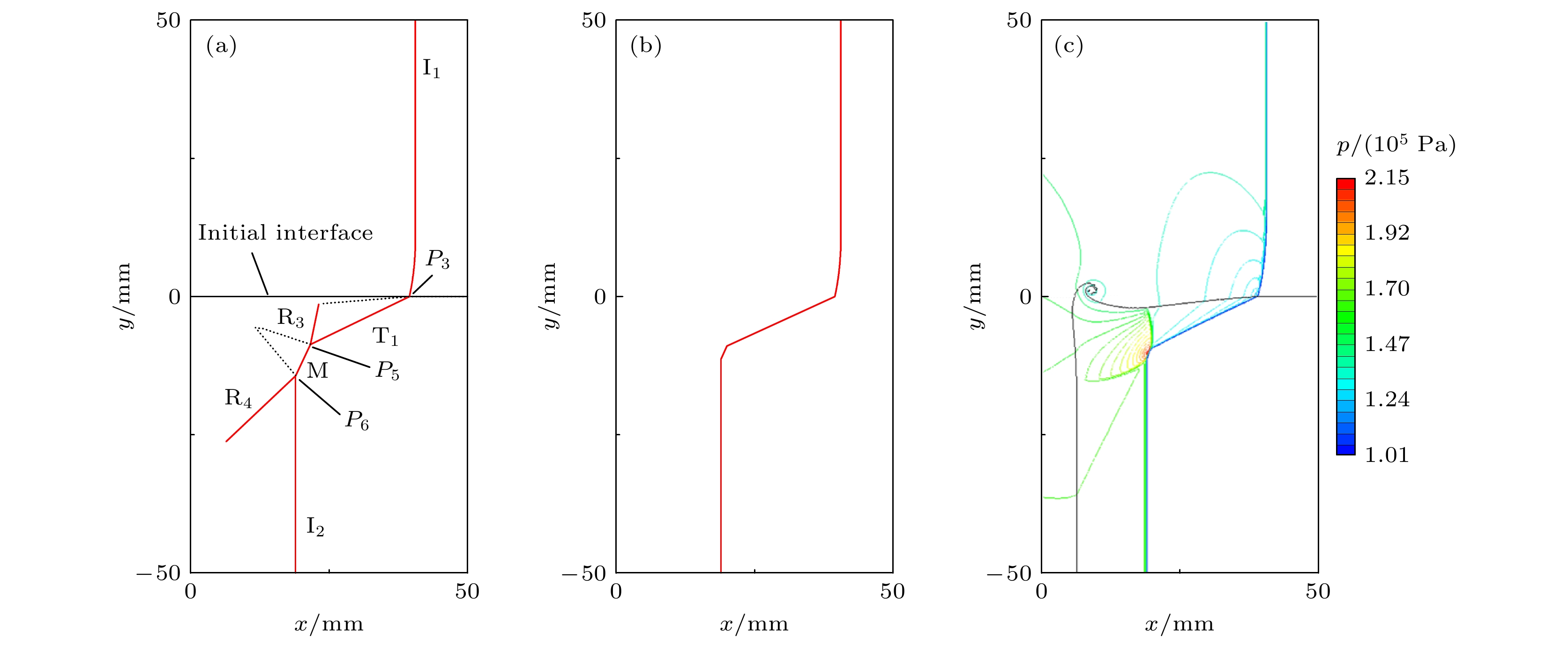
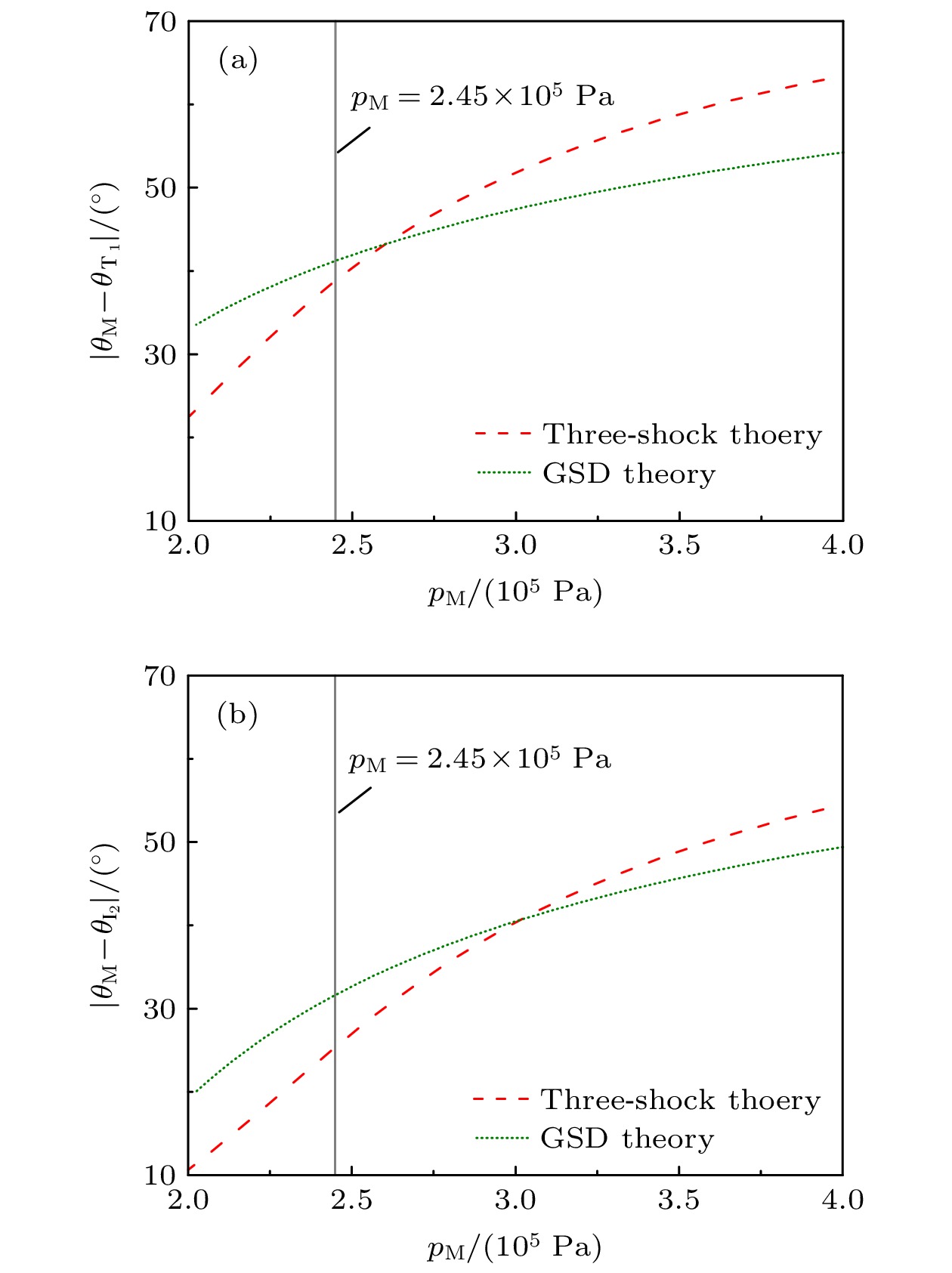
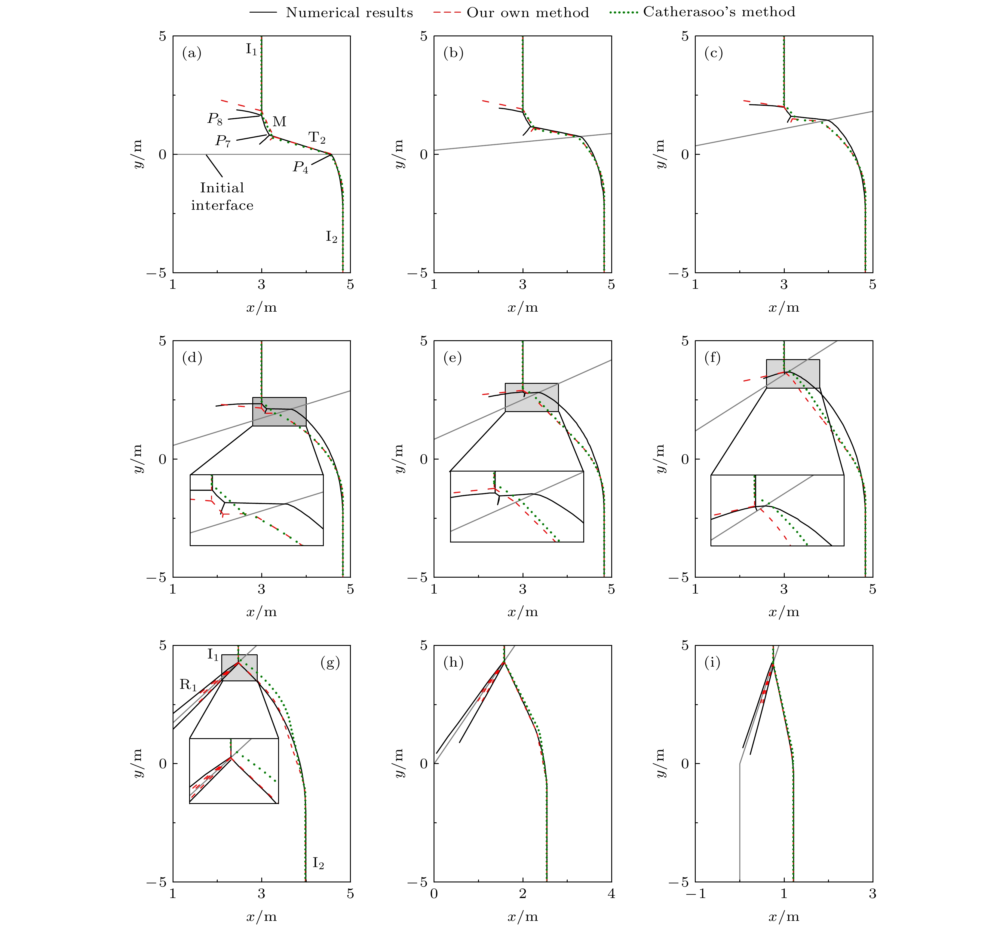
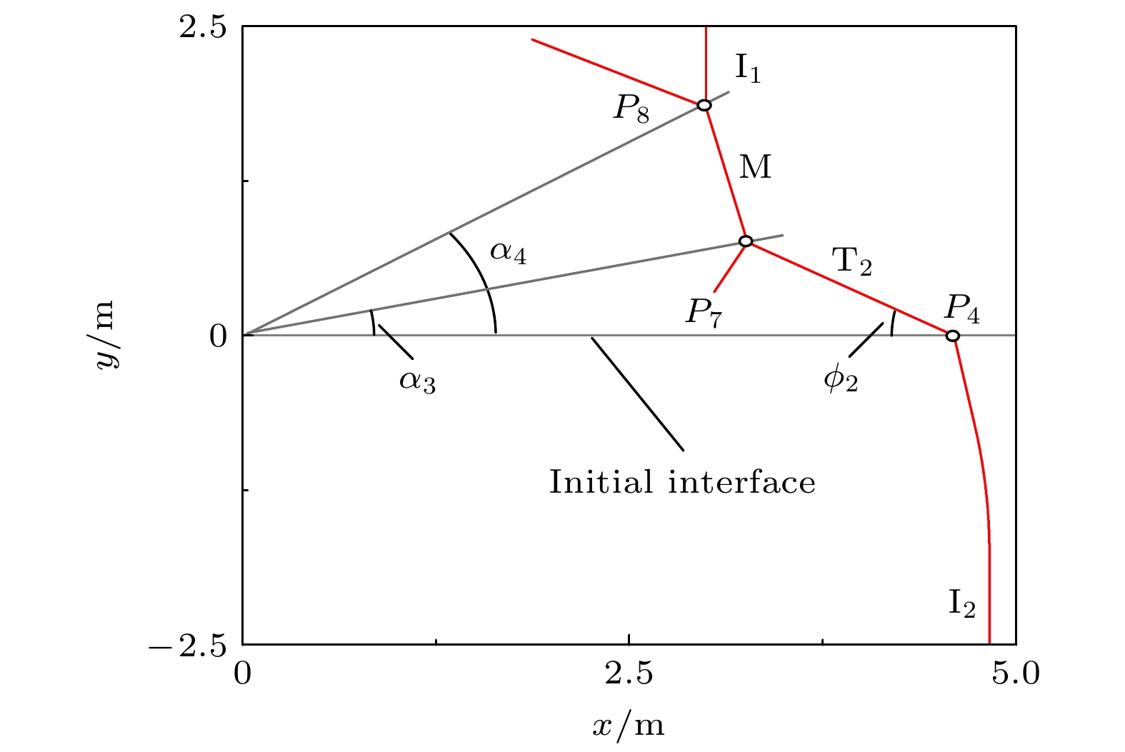
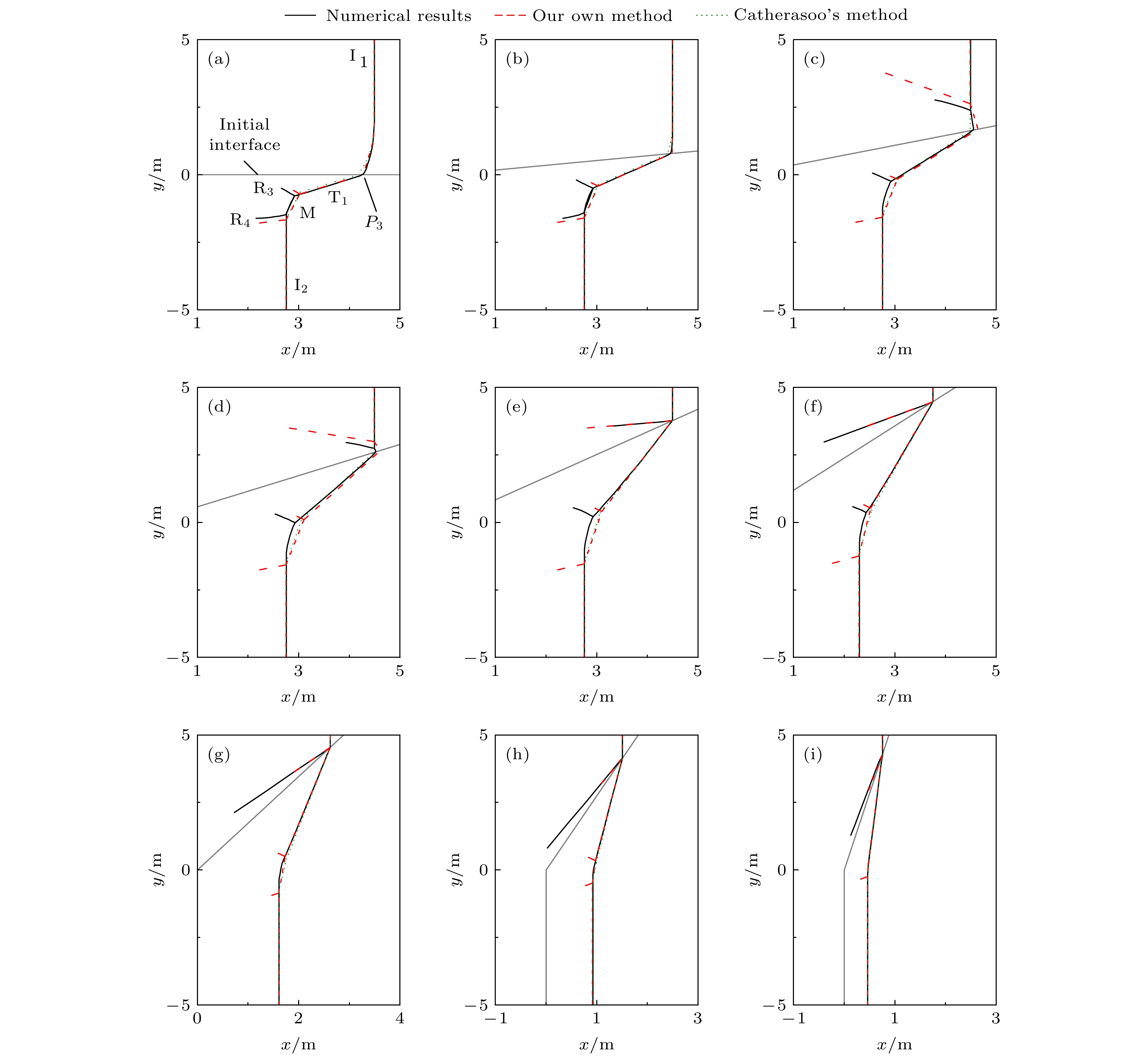
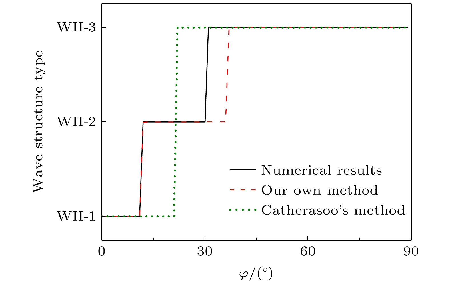
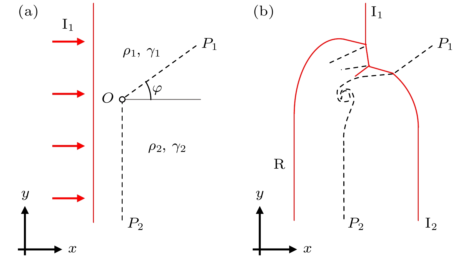
围绕二维平面激波与物质界面作用, 建立了流场波系结构的理论计算方法. 首先分析了界面两侧激波独自沿界面传播过程, 识别了两类正规折射和三类非正规折射; 然后, 根据两侧扰动沿界面传播的相对快慢, 得到了三种不同的作用情形. 与已有的Catherasoo方法相比, 此方法: 1) 考虑了激波波后紧邻波阵面流场中扰动对界面附近折射的影响, 区分了扰动的强弱及其是否可以追赶上激波阵面; 2) 除了少数情形外, 大都基于Euler方程精确解描述流场中波系相互作用. 利用该方法对马赫数1.17的激波与空气/SF6界面作用进行计算, 得到的波系结构与数值结果、已有实验数据基本一致, 透射波阵面与水平方向夹角吻合程度优于Catherasoo结果; 给出了反射波参数、界面偏折角度等, 而Catherasoo方法不能计算这些参数. 对于马赫数2.00的激波, 通过比较不同介质密度比和界面倾角下的理论与数值结果, 发现此方法对波系类型的识别比Catherasoo方法更为准确, 且识别了波后强扰动追赶上激波形成三波结构的折射类型, 后者无法识别此类型. 上述结果表明, 新方法具有良好的适用性, 对波系类型的识别较已有方法的准确度更高, 可获取更为丰富的波系结构信息.A theoretical calculation method for wave structures in the flow resulting from the interaction between the two-dimensional planar shock and the material interface is developed. First, the propagation of the shock wave on either side of the interface is analyzed, and two regular refraction types and three irregular ones are identified. Then, according to the relative speed of the perturbations on either side, three different interaction cases are established. Compared with the existing Catherasoo’s method, this method is improved in the following aspects: 1) the influence of the perturbation in the post-shock flow field on the interaction is taken into account, including its type and whether it can catch up and interact with the shock front; 2) the interactions between different waves are calculated mostly based on the exact solutions of the Euler equations, except those involving post-shock subsonic rarefaction waves. This method has been used to investigate the interaction of a Mach number 1.17 shock with an air/SF6 interface, and give wave structures that accord with numerical results and existing experimental data. The angle between the transmitted shock and the horizontal direction is obtained to be in better agreement with experimental data than Catherasoo’s result, and more parameters are obtained, such as the reflected wave and the interface deflection angle. For cases involving a Mach number 2.00 shock with different material density ratios and interface inclination angles, comparisons between theoretical and numerical results show that our method can obtain the type of wave structure more accurately than Catherasoo’s method, and identify a refraction type in which the post-shock strong perturbation catches up with the shock front and a three-wave structure is formed, whereas Catherasoo’s method cannot handle this case. Thus, the results show that the improved method in this work has better applicability and higher accuracy than the existing method in identifying the type of wave structure, and can also provide more information about the wave structures.
-
Keywords:
- shock wave /
- regular/irregular refraction /
- wave structures /
- theoretical calculation
[1] Taub A H 1947 Phys. Rev. 72 51
 Google Scholar
[2] Polachek H, Seeger R J 1951 Phys. Rev. 84 922
 Google Scholar
[3] Henderson L F 1966 J. Fluid Mech. 26 607
 Google Scholar
[4] Ben-Dor G, Igra O, Elperin T 2001 Handbook of Shock Waves (Vol. 2) (London: Academic Press) pp71,72
[5] Jahn R G 1956 J. Fluid Mech. 1 457
 Google Scholar
[6] Abd-El-Fattah A M, Henderson L F, Lozzi A 1976 J. Fluid Mech. 76 157
 Google Scholar
[7] Flores J, Holt M 1982 Phys. Fluids 25 238
 Google Scholar
[8] Henderson L F, Jia-Huan M, Akira S, Kazuyoshi T 1990 Fluid Dyn. Res. 5 337
 Google Scholar
[9] Henderson L F 1992 Shock Waves 2 103
 Google Scholar
[10] Abd-El-Fattah A M, Henderson L F 1978 J. Fluid Mech. 86 15
 Google Scholar
[11] Abd-El-Fattah A M, Henderson L F 1978 J. Fluid Mech. 89 79
 Google Scholar
[12] Henderson L F 1989 J. Fluid Mech. 198 365
 Google Scholar
[13] Henderson L F, Colella P, Puckett E G 1991 J. Fluid Mech. 224 1
 Google Scholar
[14] Henderson L F, Puckett E G 2014 Shock Waves 24 553
 Google Scholar
[15] Nourgaliev R R, Sushchikh S Y, Dinh T N, Theofanous T G 2005 Int. J. Multiphas. Flow 31 969
 Google Scholar
[16] Zhai Z G, Wang M H, Si T, Luo X S 2014 J. Fluid Mech. 757 800
 Google Scholar
[17] Wang M H, Si T, Luo X S 2015 Shock Waves 25 347
 Google Scholar
[18] Luo X S, Wang M H, Si T, Zhai Z G 2015 J. Fluid Mech. 773 366
 Google Scholar
[19] Zhai Z G, Li W, Si T, Luo X S, Yang J M, Lu X Y 2017 Phys. Fluids 29 016102
 Google Scholar
[20] Igra D, Igra O 2018 Phys. Fluids 30 056104
 Google Scholar
[21] Sadin D V, Davidchuk V A 2020 J. Eng. Phys. Thermophys. 93 474
 Google Scholar
[22] Onwuegbu S, Yang Z 2022 AIP Adv. 12 025215
 Google Scholar
[23] Georgievskii P, Levin V, Sutyrin O 2010 Fluid Dyn. 45 281
 Google Scholar
[24] Georgievskiy P, Levin V, Sutyrin O 2012 Proceedings of the 15th International Symposium on Flow Visualization Minsk, Belarus, June 25-28, 2012 p1
[25] Catherasoo C J, Sturtevant B 1983 J. Fluid Mech. 127 539
 Google Scholar
[26] Whitham G B 1957 J. Fluid Mech. 2 145
 Google Scholar
[27] Whitham G B 1959 J. Fluid Mech. 5 369
 Google Scholar
[28] Schwendeman D W 1988 J. Fluid Mech. 188 383
 Google Scholar
[29] Toro E F 2009 Riemann Solvers and Numerical Methods for Fluid Dynamics (3rd Ed.) (Berlin, Heidelberg: Springers-Verlag) pp115–151
-
表 1 波T1参数的理论计算结果
Table 1. Theoretical retuslts for parameters of T1.
计算方法 pT1/(105 Pa) uT1/(m·s–1) vT1/(m·s–1) 本文 1.32 15.8 –32.6 Catherasoo 1.21 9.95 –21.6 表 2 波T1与I2作用的理论计算结果
Table 2. Theoretical retuslts for interaction between T1 and I2.
波T1参数 计算方法 α1/(°) α2/(°) pM/(105 Pa) pT1 = 1.32×10⁵ Pa 本文 21.8 37.2 2.45 Catherasoo 24.9 32.0 2.23 pT1 = 1.21×10⁵ Pa 本文 21.3 36.6 2.37 Catherasoo 24.1 30.8 2.17 表 3 不同φ值下波系结构变量(MaI1 = 2.00, ρ2/ρ1 = 0.25)
Table 3. Wave structure parameters for different φ (MaI1 = 2.00, ρ2/ρ1 = 0.25).
φ/(°) 计算方法 ϕ2 α3 α4 d7–8 r4 结果/(°) 偏差/% 结果/(°) 偏差/% 结果/(°) 偏差/% 结果/m 偏差/% 结果/m 偏差/% 0 本文 29.4 –4.42 13.0 –10.1 31.7 10.6 1.13 34.2 4.60 0.86 Catherasoo 28.4 –7.89 12.2 –15.6 29.5 3.01 1.02 22.0 4.54 –0.31 10 本文 29.4 –4.62 8.97 –14.3 22.6 8.86 0.84 34.0 4.33 –0.51 Catherasoo 28.2 –8.54 7.89 –24.6 22.1 6.53 0.87 38.9 4.29 –1.33 20 本文 29.4 –5.12 5.33 –25.4 13.9 2.43 0.54 33.0 4.09 –3.34 Catherasoo 28.1 –9.28 3.97 –44.4 15.4 12.8 0.72 77.5 4.06 –3.89 30 本文 29.4 –9.64 2.01 –54.1 5.74 –27.5 0.24 2.59 3.88 –8.68 Catherasoo 28.1 –13.7 0.37 –91.7 9.12 15.0 0.59 148.7 3.86 –9.00 40 本文 — — — — 4.17 25.9 — — 4.16 –5.15 Catherasoo — — — — 5.02 51.4 — — 4.22 –3.88 50 本文 — — — — 0.82 22.7 — — 4.74 –1.27 Catherasoo — — — — 1.99 197.9 — — 4.86 1.22 60 本文 — — — — — — — — 4.94 –0.06 Catherasoo — — — — 0.71 — — — 5.05 2.12 70 本文 — — — — — — — — 4.60 –0.85 Catherasoo — — — — — — — — 4.60 –0.85 80 本文 — — — — — — — — 4.31 –0.98 Catherasoo — — — — — — — — 4.31 –0.98 表 4 不同φ值下波系结构变量(MaI1 = 2.00, ρ2/ρ1 = 4.00)
Table 4. Wave structure parameters for different φ (MaI1 = 2.00, ρ2/ρ1 = 4.00).
φ/(°) 计算方法 ϕ1 α1 α2 d5–6 r3 结果/(°) 偏差/% 结果/(°) 偏差/% 结果/(°) 偏差/% 结果/m 偏差/% 结果/m 偏差/% 0 本文 29.6 –2.32 13.3 –11.4 31.2 11.3 0.99 40.4 4.27 0.83 Catherasoo 29.4 –3.02 12.0 –20.0 31.0 10.5 1.04 48.1 4.17 –1.61 10 本文 29.5 –2.64 17.8 –9.35 40.2 8.18 1.22 31.2 4.56 0.69 Catherasoo 29.8 –1.64 16.8 –14.2 39.6 6.55 1.23 32.5 4.46 –1.51 20 本文 29.4 –1.14 23.0 –6.63 49.8 — 1.44 — 4.94 1.78 Catherasoo 30.2 1.73 22.0 –10.9 48.8 — 1.44 — 4.78 –1.53 30 本文 29.5 3.20 28.0 –6.96 59.7 — 1.71 — 5.32 1.96 Catherasoo 29.9 4.53 27.4 –9.10 58.4 — 1.66 — 5.19 –0.68 40 本文 27.5 3.74 32.6 –9.07 69.2 — 1.97 — 5.86 0.14 Catherasoo 27.4 3.07 33.4 –6.81 67.9 — 1.84 — 5.86 0.14 50 本文 22.8 1.86 38.1 –8.40 78.5 — 1.79 — 5.82 –0.16 Catherasoo 23.3 4.49 39.9 –3.99 77.2 — 1.65 — 5.82 –0.16 60 本文 17.6 0.12 44.0 — 88.0 — 1.36 — 5.24 0.01 Catherasoo 18.3 3.71 46.8 — 86.5 — 1.22 — 5.24 0.01 70 本文 12.0 0.36 50.1 — 97.7 — 0.84 — 4.38 –0.45 Catherasoo 12.5 4.35 54.0 — 95.8 — 0.73 — 4.38 –0.45 80 本文 6.10 –0.64 56.4 — 107.5 — 0.45 — 4.31 –0.73 Catherasoo 6.35 3.47 60.9 — 105.0 — 0.39 — 4.31 –0.73 -
[1] Taub A H 1947 Phys. Rev. 72 51
 Google Scholar
[2] Polachek H, Seeger R J 1951 Phys. Rev. 84 922
 Google Scholar
[3] Henderson L F 1966 J. Fluid Mech. 26 607
 Google Scholar
[4] Ben-Dor G, Igra O, Elperin T 2001 Handbook of Shock Waves (Vol. 2) (London: Academic Press) pp71,72
[5] Jahn R G 1956 J. Fluid Mech. 1 457
 Google Scholar
[6] Abd-El-Fattah A M, Henderson L F, Lozzi A 1976 J. Fluid Mech. 76 157
 Google Scholar
[7] Flores J, Holt M 1982 Phys. Fluids 25 238
 Google Scholar
[8] Henderson L F, Jia-Huan M, Akira S, Kazuyoshi T 1990 Fluid Dyn. Res. 5 337
 Google Scholar
[9] Henderson L F 1992 Shock Waves 2 103
 Google Scholar
[10] Abd-El-Fattah A M, Henderson L F 1978 J. Fluid Mech. 86 15
 Google Scholar
[11] Abd-El-Fattah A M, Henderson L F 1978 J. Fluid Mech. 89 79
 Google Scholar
[12] Henderson L F 1989 J. Fluid Mech. 198 365
 Google Scholar
[13] Henderson L F, Colella P, Puckett E G 1991 J. Fluid Mech. 224 1
 Google Scholar
[14] Henderson L F, Puckett E G 2014 Shock Waves 24 553
 Google Scholar
[15] Nourgaliev R R, Sushchikh S Y, Dinh T N, Theofanous T G 2005 Int. J. Multiphas. Flow 31 969
 Google Scholar
[16] Zhai Z G, Wang M H, Si T, Luo X S 2014 J. Fluid Mech. 757 800
 Google Scholar
[17] Wang M H, Si T, Luo X S 2015 Shock Waves 25 347
 Google Scholar
[18] Luo X S, Wang M H, Si T, Zhai Z G 2015 J. Fluid Mech. 773 366
 Google Scholar
[19] Zhai Z G, Li W, Si T, Luo X S, Yang J M, Lu X Y 2017 Phys. Fluids 29 016102
 Google Scholar
[20] Igra D, Igra O 2018 Phys. Fluids 30 056104
 Google Scholar
[21] Sadin D V, Davidchuk V A 2020 J. Eng. Phys. Thermophys. 93 474
 Google Scholar
[22] Onwuegbu S, Yang Z 2022 AIP Adv. 12 025215
 Google Scholar
[23] Georgievskii P, Levin V, Sutyrin O 2010 Fluid Dyn. 45 281
 Google Scholar
[24] Georgievskiy P, Levin V, Sutyrin O 2012 Proceedings of the 15th International Symposium on Flow Visualization Minsk, Belarus, June 25-28, 2012 p1
[25] Catherasoo C J, Sturtevant B 1983 J. Fluid Mech. 127 539
 Google Scholar
[26] Whitham G B 1957 J. Fluid Mech. 2 145
 Google Scholar
[27] Whitham G B 1959 J. Fluid Mech. 5 369
 Google Scholar
[28] Schwendeman D W 1988 J. Fluid Mech. 188 383
 Google Scholar
[29] Toro E F 2009 Riemann Solvers and Numerical Methods for Fluid Dynamics (3rd Ed.) (Berlin, Heidelberg: Springers-Verlag) pp115–151
计量
- 文章访问数: 7576
- PDF下载量: 92
- 被引次数: 0


 下载:
下载:


