-
比例积分调节单相H桥光伏逆变器存在复杂的分岔与混沌等非线性行为, 这些非线性行为会大大增加输出电流的谐波含量, 降低系统运行的稳定性与供电可靠性. 现有的混沌控制方法存在建模复杂、控制系数难以确定等问题. 针对于此, 本文提出了一种改进指数延迟反馈控制方法. 该方法首先利用系统输出电流与其自身延迟的差值形成反馈信号, 然后将该反馈信号通过指数环节、作差环节和比例环节得到控制信号, 并将该控制信号以反馈的形式施加于被控系统, 同时建立系统的离散映射模型并求取系统雅克比矩阵表达式; 最后基于稳定判据推导出该控制信号的反馈控制系数的限定条件并实施对系统的控制. 为了验证该方法的控制效果, 进行了大量的仿真实验. 结果表明, 该方法能有效抑制系统中的混沌行为, 大大扩展系统稳定运行域.
-
关键词:
- 比例积分调节 /
- 单相H桥光伏逆变器 /
- 混沌控制 /
- 改进指数延迟反馈控制
There are complex nonlinear behaviors such as bifurcation and chaos in a single-phase H-bridge photovoltaic inverter under proportional integral control, which will increase the harmonic content of the output current greatly and reduce the stability of system operation and reliability of power supply. There are the problems suffering the complicated modeling and difficulty in determining the control coefficients in existing chaos control methods. The exponential delay feedback control is a further development of the delay feedback control, which has the advantages of requiring no precise mathematical model of the system and simple implementation. However, our research shows that when the exponential delay feedback control is directly applied to the system, the feedback intensity cannot be controlled, which will bring too big a disturbance to the system. Based on it, an improved exponential delayed feedback control method is proposed in this paper. Firstly, a feedback signal is formed by the difference between the output current of the system and its own delay, then the feedback signal is used to obtain the control signal through an exponential link, a subtraction link and an proportion link, and the control signal is applied to the controlled system in the form of a feedback. At the same time, the discrete mapping model of the system is established and its Jacobian matrix expression is determined. Finally, the limiting conditions of the feedback control coefficient of the control signal are derived based on the stability criterion, and the control is applied to the system. In order to verify the control effect of this method, a lot of simulation experiments are conducted. The results show that the problems that the exponential delay feedback cannot control the feedback strength and causes excessive disturbance to the system will be effectively solved by this method. When the bifurcation parameters vary greatly, the chaos behaviors in the system will be suppressed effectively, the stable operating domain of the system will be expanded greatly and the harmonic content of the output current will be reduced.-
Keywords:
- proportional integral control /
- single-phase H-bridge photovoltaic inverter /
- chaos control /
- improved exponential delay feedback control
[1] 谢玲玲, 龚仁喜, 卓浩泽, 马献花 2012 61 058401
 Google Scholar
Xie L L, Gong R X, Zhuo H Z, Ma X H 2012 Acta Phys. Sin. 61 058401
 Google Scholar
[2] Zhusubaliyev Z T, Mosekilde E, Yanochkina O O 2011 IEEE Trans. Power Electron. 26 1270
 Google Scholar
[3] Kapat S 2019 IEEE Trans. Circuits Syst. Express Briefs 66 1048
 Google Scholar
[4] Ma W, Wang L, Zhang R, Li J H, Dong Z M, Zhang Y H, Hu M, Liu S X 2019 IEEE Trans. Circuits Syst. Express Briefs 66 1411
 Google Scholar
[5] Xie F, Yang R, Zhang B 2011 IEEE Trans. Circuits Syst. Regul. Pap. 58 2269
 Google Scholar
[6] Han Y, Fang X, Yang P, Wang C L, Xu L, Guerrero J M 2018 IEEE Trans. Power Electron. 33 6333
 Google Scholar
[7] Dasgupta S, Sahoo S K, Panda S K 2011 IEEE Trans. Power Electron. 26 717
 Google Scholar
[8] Zhang H, Ding H H, Yi C Z 2017 Int. J. Bifurcation Chaos 27 1750086
 Google Scholar
[9] Lei B, Xiao G C, Wu X L, Kafle Y R, Zheng L F 2014 Int. J. Bifurcation Chaos 24 1450002
 Google Scholar
[10] Tong Y N, Li C L, Zhou F 2016 Optik 127 1724
 Google Scholar
[11] Li M, Dai D, Ma X K 2008 Circuits Syst. Signal Process. 27 811
 Google Scholar
[12] Liu W, Wang F Q, Ma X K 2016 Int. J. Bifurcation Chao. 26 1650200
 Google Scholar
[13] Avrutin V, Mosekilde E, Zhusubaliyev Z T, Gardini L 2015 Chao. 25 043114
 Google Scholar
[14] Robert B, Robert C 2002 Int. J. Control. 75 1356
 Google Scholar
[15] Asahara H, Kousaka T 2011 Int. J. Bifurcation Chaos 21 985
 Google Scholar
[16] Yang F, Yang L H, Ma X K 2016 Int. J. Bifurcation Chaos 26 1650199
 Google Scholar
[17] Hsieh F H, Wang H K, Chang P L, Chen Y S, Yang Y K 2009 Int. J. Innov. Comput. Inf. Control. 5 4647
[18] Yang L H, Yang L, Yang F, Ma X K 2020 Int. J. Bifurcation Chaos 30 2050005
 Google Scholar
[19] 刘洪臣, 李飞, 杨爽 2013 62 110504
 Google Scholar
Liu H C, Li F, Yang S, 2013 Acta Phys. Sin. 62 110504
 Google Scholar
[20] 刘洪臣, 杨爽 2013 62 210502
 Google Scholar
Liu H C, Yang S, 2013 Acta Phys. Sin. 62 210502
 Google Scholar
[21] Iu H H C, Robert B 2003 IEEE Trans. Circuits Syst. I -Fundam. Theor. Appl. 50 1125
 Google Scholar
[22] Feki A, Robert B, Iu H H C 2004 35th Annual IEEE Power Electronics Specialists Conference Aachen Germany, 20−25 June 2004, p3317
[23] Lu W G, Zhao N K, Wu J K, Aroudi E A, Zhou L W 2015 Int. J. Circuit Theory Appl. 43 866
 Google Scholar
[24] Nakajima H, Ueda Y 1998 Physica D 111 143
 Google Scholar
-
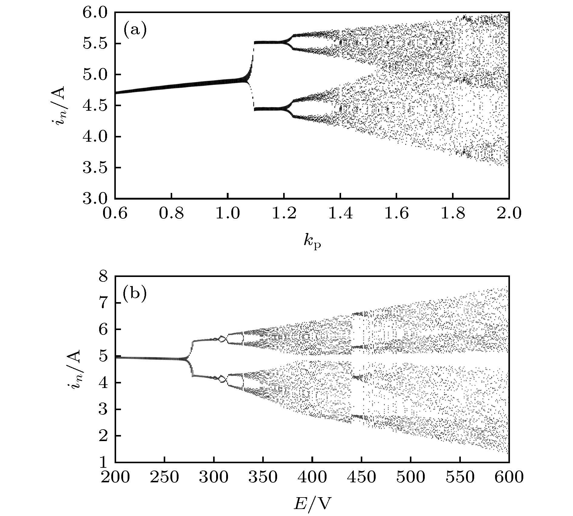
图 2 未引入混沌控制时电感电流峰值处分岔图(n = 100+400k, k = 1, 2, 3, ···) (a) kp为分岔参数时分岔图; (b) E为分岔参数时分岔图
Fig. 2. Bifurcation diagram with inductance current at peak value without chaos control (n = 100+ 400k, k = 1, 2, 3, ···): (a) Bifurcation diagram with kp as bifurcation parameter; (b) bifurcation diagram with E as bifurcation parameter.
图 4 引入EDFC后电感电流峰值处分岔图 (n = 100+400k, k = 1, 2, 3, ···) (a) kp为分岔参数时分岔图; (b) E为分岔参数时分岔图
Fig. 4. Bifurcation diagram with inductance current at peak value with EDFC applied (n = 100+ 400k, k = 1, 2, 3···): (a) Bifurcation diagram with kp as bifurcation parameter; (b) bifurcation diagram with E as bifurcation parameter
图 6 引入IEDFC后电感电流峰值处分岔图 (n = 100+400k, k = 1, 2, 3, ···) (a) 以kp为分岔参数时分岔图; (b) 以E为分岔参数时分岔图
Fig. 6. Bifurcation diagram with inductance current at peak value with IEDFC applied (n = 100+400k, k = 1, 2, 3, ···): (a) Bifurcation diagram with kp as bifurcation parameter; (b) bifurcation diagram with E as bifurcation parameter
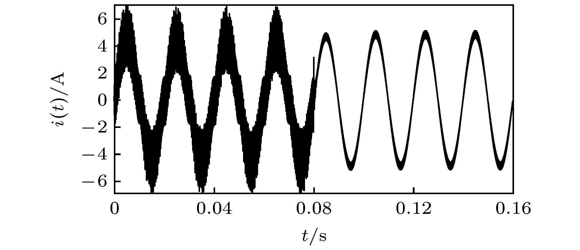
图 13 kp = 1.4, t = 0.06 s时, 引入其他混沌控制后电感电流 (a) 引入时间延迟反馈控制后; (b) 引入扩展时间延迟反馈控制后; (c) 引入基于滤波器的混沌控制后
Fig. 13. Inductor current with other chaos control applied for kp = 1.4, t = 0.06 s: (a) With time-delay feedback control applied; (b) with extended time-delay feedback control applied; (c) with chaos control based on filter applied.
表 1 电路参数设定值
Table 1. Set values of circuit parameters.
电路参数 取值 电路参数 取值 直流侧输入电压E/V 250 载波itri的最大值 1 电感L/mH 7 载波itri的最小值 –1 电阻R/Ω 20 积分控制系数ki 180 给定参考电流幅值
irefm/A5 开关频率fs/kHz 20 载波itri的周期T/μs 50 调制信号icon的
周期Ts/s0.02 -
[1] 谢玲玲, 龚仁喜, 卓浩泽, 马献花 2012 61 058401
 Google Scholar
Xie L L, Gong R X, Zhuo H Z, Ma X H 2012 Acta Phys. Sin. 61 058401
 Google Scholar
[2] Zhusubaliyev Z T, Mosekilde E, Yanochkina O O 2011 IEEE Trans. Power Electron. 26 1270
 Google Scholar
[3] Kapat S 2019 IEEE Trans. Circuits Syst. Express Briefs 66 1048
 Google Scholar
[4] Ma W, Wang L, Zhang R, Li J H, Dong Z M, Zhang Y H, Hu M, Liu S X 2019 IEEE Trans. Circuits Syst. Express Briefs 66 1411
 Google Scholar
[5] Xie F, Yang R, Zhang B 2011 IEEE Trans. Circuits Syst. Regul. Pap. 58 2269
 Google Scholar
[6] Han Y, Fang X, Yang P, Wang C L, Xu L, Guerrero J M 2018 IEEE Trans. Power Electron. 33 6333
 Google Scholar
[7] Dasgupta S, Sahoo S K, Panda S K 2011 IEEE Trans. Power Electron. 26 717
 Google Scholar
[8] Zhang H, Ding H H, Yi C Z 2017 Int. J. Bifurcation Chaos 27 1750086
 Google Scholar
[9] Lei B, Xiao G C, Wu X L, Kafle Y R, Zheng L F 2014 Int. J. Bifurcation Chaos 24 1450002
 Google Scholar
[10] Tong Y N, Li C L, Zhou F 2016 Optik 127 1724
 Google Scholar
[11] Li M, Dai D, Ma X K 2008 Circuits Syst. Signal Process. 27 811
 Google Scholar
[12] Liu W, Wang F Q, Ma X K 2016 Int. J. Bifurcation Chao. 26 1650200
 Google Scholar
[13] Avrutin V, Mosekilde E, Zhusubaliyev Z T, Gardini L 2015 Chao. 25 043114
 Google Scholar
[14] Robert B, Robert C 2002 Int. J. Control. 75 1356
 Google Scholar
[15] Asahara H, Kousaka T 2011 Int. J. Bifurcation Chaos 21 985
 Google Scholar
[16] Yang F, Yang L H, Ma X K 2016 Int. J. Bifurcation Chaos 26 1650199
 Google Scholar
[17] Hsieh F H, Wang H K, Chang P L, Chen Y S, Yang Y K 2009 Int. J. Innov. Comput. Inf. Control. 5 4647
[18] Yang L H, Yang L, Yang F, Ma X K 2020 Int. J. Bifurcation Chaos 30 2050005
 Google Scholar
[19] 刘洪臣, 李飞, 杨爽 2013 62 110504
 Google Scholar
Liu H C, Li F, Yang S, 2013 Acta Phys. Sin. 62 110504
 Google Scholar
[20] 刘洪臣, 杨爽 2013 62 210502
 Google Scholar
Liu H C, Yang S, 2013 Acta Phys. Sin. 62 210502
 Google Scholar
[21] Iu H H C, Robert B 2003 IEEE Trans. Circuits Syst. I -Fundam. Theor. Appl. 50 1125
 Google Scholar
[22] Feki A, Robert B, Iu H H C 2004 35th Annual IEEE Power Electronics Specialists Conference Aachen Germany, 20−25 June 2004, p3317
[23] Lu W G, Zhao N K, Wu J K, Aroudi E A, Zhou L W 2015 Int. J. Circuit Theory Appl. 43 866
 Google Scholar
[24] Nakajima H, Ueda Y 1998 Physica D 111 143
 Google Scholar
计量
- 文章访问数: 6867
- PDF下载量: 113
- 被引次数: 0


 下载:
下载:
