-
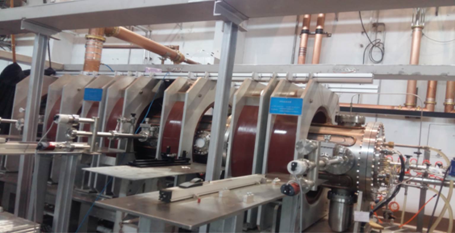
近年来, 螺旋波等离子体源在核聚变条件下等离子体与材料的相互作用方面具有十分重要的研究意义. 本文对高密度螺旋波等离子体原型实验装置(helicon physics prototype experiment, HPPX)中的螺旋波系统发射天线进行了优化设计, 利用HELIC程序, 对螺旋波的耦合和功率沉积与天线的类型、天线长度、运行频率等关键参数的相互关系作了数值模拟计算, 进而给出了天线的最佳天线结构和物理尺寸. 同时还分析了静磁场强度和轴心等离子体密度对功率沉积及其分布的影响, 发现等离子体对螺旋波的吸收功率在多个静磁场和轴心密度处有不同的峰值功率点, 且整体的耦合趋势随静磁场增大呈上升的趋势, 而随轴心密度增大是下降的趋势; 并根据这些仿真结果深入探讨了螺旋波等离子体的电离机制. 为了进一步研究HPPX装置中螺旋波与等离子体耦合的问题, 还给出了等离子体放电时的感生电磁场与电流密度的分布情况. 本文工作可为HPPX装置上螺旋波天线设计和相关物理实验提供理论依据.
Recently, helicon plasma sources have aroused the great interest particularly in plasma-material interaction under fusion conditions. In this paper, the helicon wave antenna in helicon physics prototype experiment (HPPX) is optimized. To reveal the effect of the radial density configuration on wave field and energy flow, Maxwell's equations for a radially nonuniform plasma with standard cold-plasma dielectric tensor are solved. Helicon wave coupling and power deposition are studied under different types of antennas, different antenna lengths and driving frequencies by using HELIC. Through the numerical simulation, the optimal antenna structure and size are obtained, that is, half helix antenna, which works at 13.56 MHz and has a length of 0.4 m, can generate nonaxisymmetric radio frequency energy coupling to excite higher electron density. The influences of different static magnetic fields and axis plasma densities on power deposition are also analyzed. It is found that the absorbed power of the plasma to the helicon wave has different peak power points in a multiple static magnetic field and axial plasma densities, and the overall coupling trend increases with static magnetic field increasing, but decreases with axis plasma density increasing. According to the simulation results, the ionization mechanism of helicon plasma is discussed. In order to further study the coupling of helicon wave with plasma in HPPX, the induced electromagnetic field and current density distribution are given when the plasma discharges. Under parabolic density distribution, the field intensity of the induced electric field at the edge is large, while neither the induced magnetic field nor current density changes much along the radial direction, the energy is distributed evenly in the whole plasma. Under the Gaussian density distribution, the induced electric field intensity is higher at the edge, while the induced magnetic field and current density in the center are much higher than at the edge. In this paper studied are the structure and size of helicon wave antenna, the influences of static magnetic field and axial plasma density on plasma power deposition and the distribution of induced electromagnetic field and current density during plasma discharge under different density distributions. This work will provide important theoretical basis for helicon wave antena design and relevant physical experiments on HPPX. -
Keywords:
- helicon plasma /
- antenna /
- static magnetic field /
- axial plasma density /
- power deposition
[1] Carter M D, Baity F W, Barber G C, et al. 2002 Phys. Plasmas 9 5097
 Google Scholar
[2] Batishchev O V 2009 IEEE Trans. Plasma Sci. 37 1563
 Google Scholar
[3] Goulding R H, Caughman J B O, Rapp J, et al. 2017 Fusion Sci. Technol. 72 588
 Google Scholar
[4] Shinohara S, Nishida H, Tanikawa T, et al. 2014 IEEE Trans. Plasma Sci. 42 1245
 Google Scholar
[5] Lee M J, Jung Y D 2018 Phys. Plasmas 25 044501
 Google Scholar
[6] Gallo A, Fedorczak N, Elmore S, et al 2018 Plasma Phys. Control. Fusion 60 014007
 Google Scholar
[7] Aigrain P 1960 Proceedings of the International Conference on Semiconductor Physics Prague, Czech Republic, 1960 p224
[8] Boswell R W 1970 Phys. Lett. 33A 457
[9] Chen F F 1991 Plasma Phys. Controlled Fusion 33 339
 Google Scholar
[10] Chen F F, Blackwell D D 1999 Phys. Rev. Lett. 82 2677
[11] Krmer M, Enk T, Lorenz B 2000 Phys. Scripta T84 132
 Google Scholar
[12] Shamrai K P, Taranov V B 1996 Plasma Sources Sci. Technol. 5 474
 Google Scholar
[13] Afsharmanesh M, Habibi M 2017 Plasma Sci. Technol. 19 105403
 Google Scholar
[14] Arnush D 2000 Phys. Plasmas 7 3042
 Google Scholar
[15] Chen F F, Arnush D 1997 Phys. Plasmas 4 3411
 Google Scholar
[16] Arnush D, Chen F F 1998 Phys. Plasmas 5 1239
 Google Scholar
[17] Mouzouris Y, Scharer J E 1996 IEEE Trans. Plasma Sci. 24 152
 Google Scholar
[18] Melazzi D, Curreli D, Manente M, et al. 2012 Com. Phys. Comm. 183 1182
 Google Scholar
[19] Melazzi D, Lancellotti V 2015 Plasma Sources Sci. Technol. 24 25024
 Google Scholar
[20] 成玉国, 程谋森, 王墨戈, 等 2014 63 035203
 Google Scholar
Cheng Y G, Cheng M S, Wang M G, et al. 2014 Acta Phys. Sin. 63 035203
 Google Scholar
[21] 杨雄, 程谋森, 王墨戈, 等 2017 66 025201
 Google Scholar
Yang X, Cheng M S, Wang M G, et al. 2017 Acta Phys. Sin. 66 025201
 Google Scholar
[22] Chang L, Li Q C, Zhang H J, et al. 2016 Plasma Sci. Technol. 18 848
 Google Scholar
[23] Chang L, Hu X Y, Gao L, et al. 2018 AIP ADVANCES 8 045016
 Google Scholar
[24] Chang L, Hole M J, Corr C S 2011 Phys. Plasmas 18 042106
 Google Scholar
[25] Boswell R W 1984 Plasma Phys. Control. Fusion 26 1147
 Google Scholar
[26] Chen R T S, Breun R A, Gross S, et al. 1995 Plasma Sources Sci. Technol. 4 337
 Google Scholar
[27] Charles C, Boswell R W, Lieberman M A 2003 Phys. Plasmas 10 891
 Google Scholar
[28] Chi K K, Sheridan T E, Boswell R W 1999 Plasma Sources Sci. Technol. 8 421
 Google Scholar
[29] Jung H D, Park M J, Kim S H, et al 2004 Rev. Sci. Instrum. 75 1878
 Google Scholar
[30] Michael A L, Allan J L 2007 Principles of Plasma Discharges and Materials Processing (Beijing: Science Press) pp291, 292, 350–352, 374–379, 392–399
[31] Chen F F 2012 Phys. Plasmas 19 093509
 Google Scholar
-
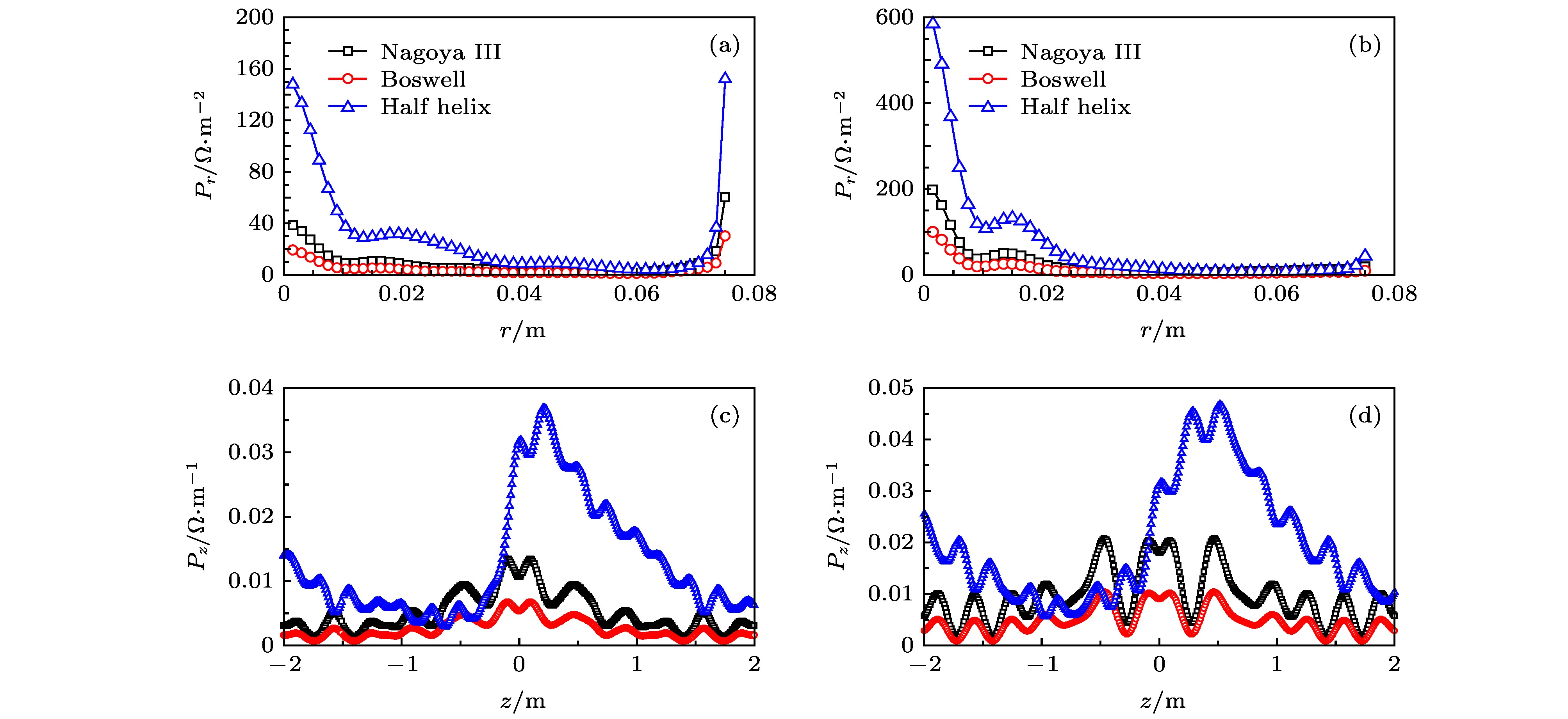
图 3 3种典型的螺旋波天线的径向(z = 0.2 m)和轴向(r = 0.02 m)相对吸收功率 (a)抛物面密度分布下3种天线的径向相对吸收功率; (b)高斯密度分布下3种天线的径向相对吸收功率; (c)抛物面密度分布下3种天线的轴向相对吸收功率; (d)高斯密度分布下3种天线的轴向相对吸收功率
Fig. 3. Relative power absorption in radial (z = 0.2 m) and axial (r = 0.02 m) directions for three typical helicon wave antennas: (a) Radial relative absorption power of three antennas under parabolic density distribution; (b) radial relative absorption power of three antennas under Gaussian density distribution; (c) axial relative absorption of power of three antennas under parabolic density distribution; (d) axial relative absorption of power of three antennas under Gaussian density distribution.
图 4 不同天线长度下的径向(z = 0.2 m)吸收功率 (a)抛物面密度分布下天线长度对径向相对吸收功率的影响; (b)高斯密度分布下天线长度对径向相对吸收功率的影响; (c)抛物面密度分布下径向吸收功率随天线长度的变化曲线; (d)高斯密度分布下径向吸收功率随天线长度的变化曲线
Fig. 4. Relative power absorption in radial (z = 0.2 m) directions for different antenna lengths: (a) Effect of antenna length on radial relative absorption power under parabolic density distribution; (b) effect of antenna length on radial relative absorption power under Gaussian density distribution; (c) radial relative absorption power of different antennas lengths under parabolic density distribution; (d) radial relative absorption power of different antennas lengths under Gaussian density distribution.
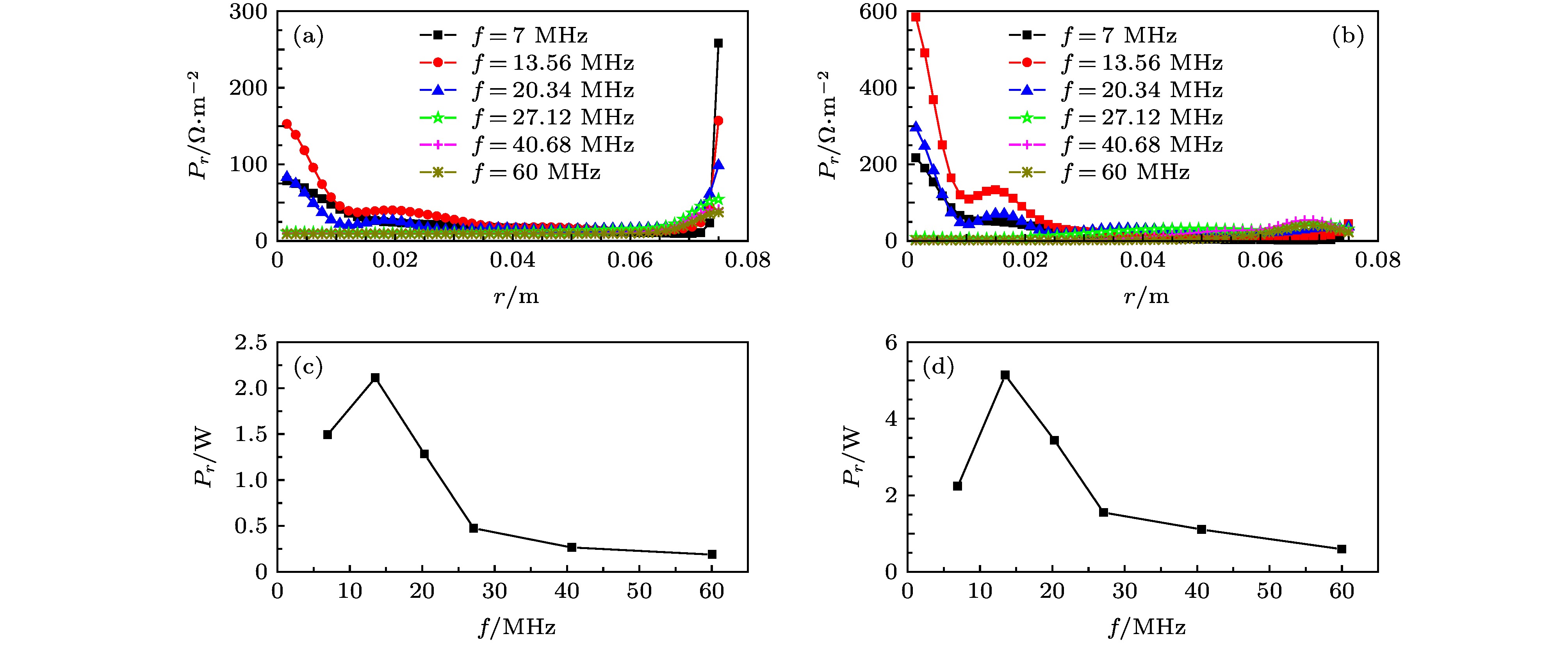
图 5 不同运行频率下的径向(z = 0.2 m)吸收功率 (a)抛物面密度分布下天线运行频率对径向相对吸收功率的影响; (b)高斯密度分布下天线运行频率对径向相对吸收功率的影响; (c) 抛物面密度分布下径向吸收功率随运行频率的变化曲线; (d)高斯密度分布下径向吸收功率随运行频率的变化曲线
Fig. 5. Relative power absorption in radial (z = 0.2 m) directions for various operating frequencies: (a) Effect of various operating frequencies on radial relative absorption power under parabolic density distribution; (b) effect of various operating frequencies on radial relative absorption power under Gaussian density distribution; (c) radial relative absorption power of various operating frequencies under parabolic density distribution; (d) radial relative absorption power of various operating frequencies under Gaussian density distribution.
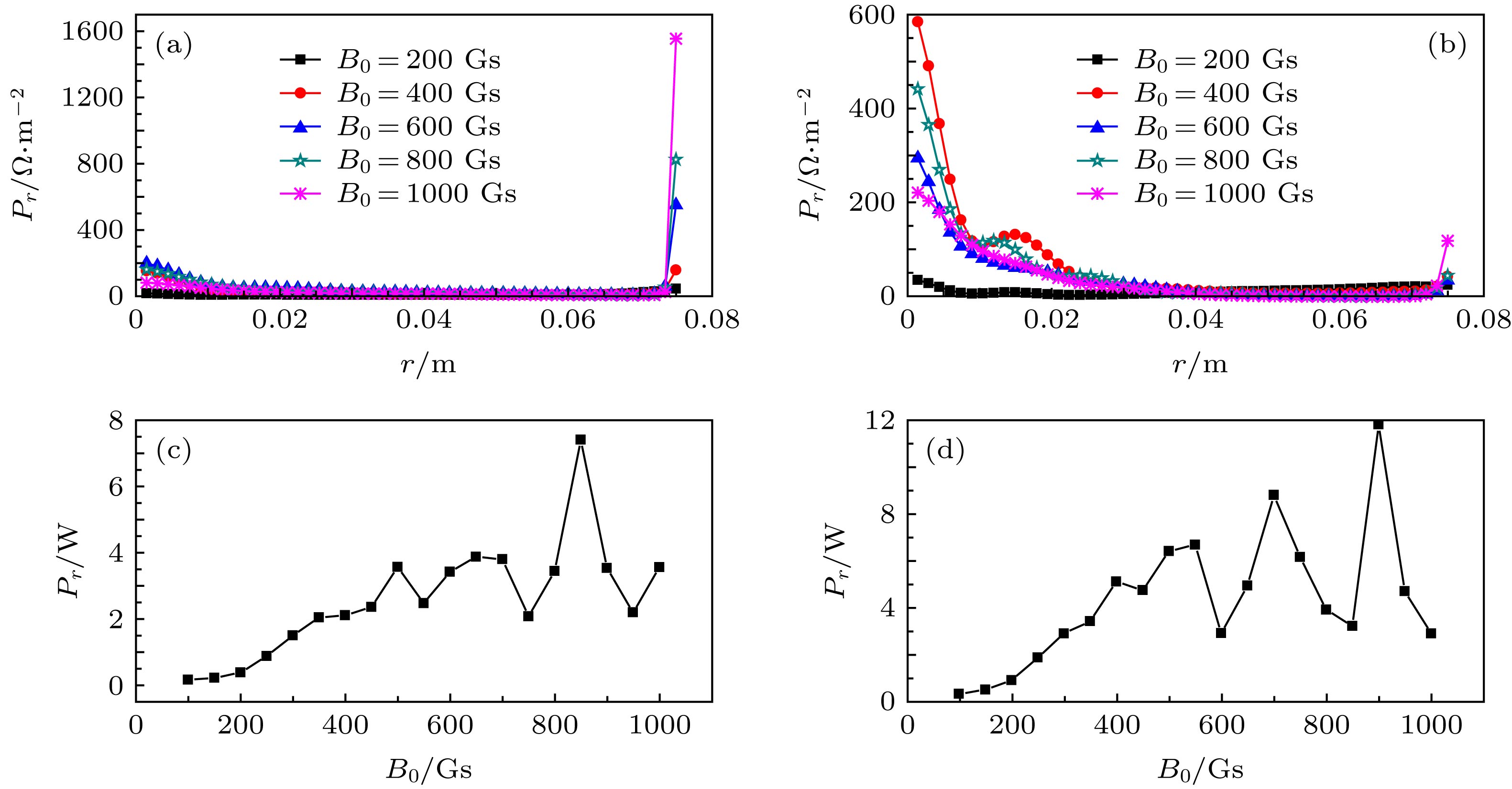
图 6 不同静磁场下的径向(z = 0.2 m)吸收功率 (a)抛物面密度分布下磁场对径向相对吸收功率的影响; (b)高斯密度分布下磁场对径向相对吸收功率的影响; (c)抛物面密度分布下径向吸收功率随磁场强度的变化曲线; (d)高斯密度分布下径向吸收功率随磁场强度的变化曲线
Fig. 6. Relative power absorption in radial (z = 0.2 m) directions for various static magnetic intensity: (a) Effect of various magnetic intensity on radial relative absorption power under parabolic density distribution; (b) effect of various magnetic intensity on radial relative absorption power under Gaussian density distribution; (c) radial relative absorption power of various magnetic intensity under parabolic density distribution; (d) radial relative absorption power of various magnetic intensity under Gaussian density distribution.
图 7 不同密度下的径向(z = 0.2 m)吸收功率 (a)抛物面密度分布下密度对径向相对吸收功率的影响; (b)高斯密度分布下密度对径向相对吸收功率的影响; (c)抛物面密度分布下径向吸收功率随密度大小的变化曲线; (d)高斯密度分布下径向吸收功率随密度大小的变化曲线
Fig. 7. Relative power absorption in radial (z = 0.2 m) directions for various density: (a) Effect of various density on radial relative absorption power under parabolic density distribution; (b) effect of various density on radial relative absorption power under Gaussian density distribution; (c) radial relative absorption power of various density under parabolic density distribution; (d) radialrelative absorption power of various density under Gaussian density distribution.
表 1 HPPX装置参数及等离子体参数
Table 1. HPPX device parameters and plasma parameters.
参数 数值 等离子体半径Ra/m 0.075 天线半径Rb/m 0.2 真空腔半径Rc/m 0.25 工质粒子种类 Ar+ 射频天线运行频率f/MHz 13.56 射频天线长度LA/m 0.4 中心轴处等离子体密度ne0/cm–3 4 × 10¹² 轴向静磁场强度B0/T 0.04 电子温度Te0/eV 5 中性轴压强Pg0/mTorr 10 步长N 49 碰撞因子 1 -
[1] Carter M D, Baity F W, Barber G C, et al. 2002 Phys. Plasmas 9 5097
 Google Scholar
[2] Batishchev O V 2009 IEEE Trans. Plasma Sci. 37 1563
 Google Scholar
[3] Goulding R H, Caughman J B O, Rapp J, et al. 2017 Fusion Sci. Technol. 72 588
 Google Scholar
[4] Shinohara S, Nishida H, Tanikawa T, et al. 2014 IEEE Trans. Plasma Sci. 42 1245
 Google Scholar
[5] Lee M J, Jung Y D 2018 Phys. Plasmas 25 044501
 Google Scholar
[6] Gallo A, Fedorczak N, Elmore S, et al 2018 Plasma Phys. Control. Fusion 60 014007
 Google Scholar
[7] Aigrain P 1960 Proceedings of the International Conference on Semiconductor Physics Prague, Czech Republic, 1960 p224
[8] Boswell R W 1970 Phys. Lett. 33A 457
[9] Chen F F 1991 Plasma Phys. Controlled Fusion 33 339
 Google Scholar
[10] Chen F F, Blackwell D D 1999 Phys. Rev. Lett. 82 2677
[11] Krmer M, Enk T, Lorenz B 2000 Phys. Scripta T84 132
 Google Scholar
[12] Shamrai K P, Taranov V B 1996 Plasma Sources Sci. Technol. 5 474
 Google Scholar
[13] Afsharmanesh M, Habibi M 2017 Plasma Sci. Technol. 19 105403
 Google Scholar
[14] Arnush D 2000 Phys. Plasmas 7 3042
 Google Scholar
[15] Chen F F, Arnush D 1997 Phys. Plasmas 4 3411
 Google Scholar
[16] Arnush D, Chen F F 1998 Phys. Plasmas 5 1239
 Google Scholar
[17] Mouzouris Y, Scharer J E 1996 IEEE Trans. Plasma Sci. 24 152
 Google Scholar
[18] Melazzi D, Curreli D, Manente M, et al. 2012 Com. Phys. Comm. 183 1182
 Google Scholar
[19] Melazzi D, Lancellotti V 2015 Plasma Sources Sci. Technol. 24 25024
 Google Scholar
[20] 成玉国, 程谋森, 王墨戈, 等 2014 63 035203
 Google Scholar
Cheng Y G, Cheng M S, Wang M G, et al. 2014 Acta Phys. Sin. 63 035203
 Google Scholar
[21] 杨雄, 程谋森, 王墨戈, 等 2017 66 025201
 Google Scholar
Yang X, Cheng M S, Wang M G, et al. 2017 Acta Phys. Sin. 66 025201
 Google Scholar
[22] Chang L, Li Q C, Zhang H J, et al. 2016 Plasma Sci. Technol. 18 848
 Google Scholar
[23] Chang L, Hu X Y, Gao L, et al. 2018 AIP ADVANCES 8 045016
 Google Scholar
[24] Chang L, Hole M J, Corr C S 2011 Phys. Plasmas 18 042106
 Google Scholar
[25] Boswell R W 1984 Plasma Phys. Control. Fusion 26 1147
 Google Scholar
[26] Chen R T S, Breun R A, Gross S, et al. 1995 Plasma Sources Sci. Technol. 4 337
 Google Scholar
[27] Charles C, Boswell R W, Lieberman M A 2003 Phys. Plasmas 10 891
 Google Scholar
[28] Chi K K, Sheridan T E, Boswell R W 1999 Plasma Sources Sci. Technol. 8 421
 Google Scholar
[29] Jung H D, Park M J, Kim S H, et al 2004 Rev. Sci. Instrum. 75 1878
 Google Scholar
[30] Michael A L, Allan J L 2007 Principles of Plasma Discharges and Materials Processing (Beijing: Science Press) pp291, 292, 350–352, 374–379, 392–399
[31] Chen F F 2012 Phys. Plasmas 19 093509
 Google Scholar
计量
- 文章访问数: 13247
- PDF下载量: 189
- 被引次数: 0


 下载:
下载:

