-
提出了一种三线阿基米德螺线结构产生环形磁势阱以囚禁中性原子的导引方案. 该结构具有
$ {\text{π}}/3$ 旋转对称性, 由三根导线组成. 每根导线包含一对由圆弧连接的阿基米德螺线, 且具有中心对称性. 这种结构能够避免电流引线端导致的导引缺口问题. 当加载直流电时, 可以形成闭合的环形磁导引, 但导引中心存在磁场零点. 利用时间轨道平均势原理, 在直流电的基础上再加载交流调制, 对调制电流的参数进行分析和讨论后给出优化方案, 使环形磁导引中心无磁场零点, 同时平滑了环形磁导引中心磁场强度在角向上的起伏变化. 该结构可以刻蚀在芯片表面, 具有生产工艺简单、调制稳定等优点, 有利于实现导引型原子芯片陀螺仪.We propose a scheme to create a ring magnetic guide based on Archimedean spirals. This scheme is significant to obtaining large circle area for atom interference and the realization of guided atom-interferometer gyroscopes. Then the scheme can be used to realize an inertial sensing system which is independent of the GPS system. The wires structure with $ {\text{π}}/3$ rotational symmetry is composed of three wires. Each wire is centrosymmetric and consists of a pair of Archimedean spirals connected by two arcs. Consequently, the leading wire ends of the layout can be arranged separately in the different place of the layout plane. If the leading wire ends are put together somewhere, the closed ring guide cannot form and a gap appears in the guide due to the concentrated distribution of the leading wire ends. Since the leading wire ends distribute in the different location with$ {\text{π}}/3$ rotational symmetry in our scheme, when direct currents are applied, the closed ring trap can be generated ingeniously.We calculate and analyze the magnetic field distribution generated by our structure after loading currents in the cylindrical coordinates system. To get higher sensitivity compared to GPS and make the ring trap locate in a proper height above the chip surface, we set the initial radius of Archimedean spirals $ a=5\ {\rm{mm}}$ and the distance between neighboring spirals$ d=0.1\ {\rm{mm}}$ . When three wires carry direct currents in an opposite current-phase-difference between the adjacent wires, a closed ring magnetic guide indeed appears but with six zero magnetic field points along the guide center. Because of the variation of the current density along r direction in Archimedean spirals, the magnetic field of the guide center is not zero at most angle. However, the variation cannot avoid the existence of zero points and the distribution of the zero points is determined by the rotational symmetry of the wires structure.Since atoms near the zero points of the magnetic field would be lost from the trap, the zero points must be removed from the center of the ring guide. Based on the time-orbiting-potential principle (TOP), we add an ac current modulation on the direct currents above to eliminate the influence of the zero points of the guide center. We give the ac current expressions and discuss the effects of currents parameters on the ring guide. The current phase reflects how the currents change in three wires. The modulation depth determines the effect of the modulation: if the modulation depth is too high, the trap may disappear; if the modulation depth is too low, the effect is minimal. The modulation frequency reflects the change rate of the modulation magnetic field. To ensure the smoothness of the guide along angular direction and adiabatic following of the magnetic field, we set the modulation depth $ I_j/I_i=0.1$ , the current-phase$ \phi=2{\text{π}}/3$ and the modulation frequency$ \omega_b=2{\text{π}}\times10\ {\rm{kHz}}$ . The numerical calculation results indicate that ac current modulation can change the magnetic field intensity of the guide center and smooth the variance of the magnetic field intensity of the guide along angular direction. We take the cross section of the guide with$ \theta={\text{π}}/2$ , for example. The minimum of the instantaneous magnetic field rotates and our structure has formed a TOP trap in both the r and z directions. In angular direction, the magnetic field intensity of the guide center changes near$ 0.25\ {\rm{mT}}$ . The difference between the maximum and the minimum is$ \Delta\,B\approx0.007\ {\rm{mT}}$ which is small enough compared to applying direct current only.Therefore, based on the Archimedean spirals and ac current modulation, we obtain an enclosed and smooth ring magnetic guide without zero magnetic fields along the guide center for neutral atoms. The location of the guide center also changes along the angle direction. The amplitudes of variation along r and z directions are $ \Delta r=0.015\ {\rm{mm}}$ ,$ \Delta z=0.005\ {\rm{mm}}$ , which are$ \Delta r/l\approx0.3\,\%$ ,$ \Delta z/l\approx0.1\,\%$ compared with$ l\approx2{\text{π}} a/6\approx5.236\ {\rm{mm}}$ .Compared to other schemes, our structure can be etched on an atom chip and is easily to apply modulation currents, which is simple and stable to form a ring magnetic guide. This scheme can be used to realize a compact, low power and stable inertial sensor based on atom-chip gyroscope device. -
Keywords:
- ring magnetic guide /
- Archimedean spirals /
- atom chip /
- AC modulation
[1] Luo C Y, Huang J H, Zhang X D, Lee C H 2017 Phys. Rev. A 95 023608
 Google Scholar
[2] Che Y M, Yao F, Liang H B, Li G L, Wang X G 2018 Phys. Rev. A 98 053609
 Google Scholar
[3] Yao F, Che Y M, Su Y G, Liang H B, Pei J C, Wang X G 2019 Phys. Rev. A 99 052128
 Google Scholar
[4] Barrett B, Geiger R, Dutta I, Meunier M, Canuel B, Gauguet A, Bouyer P, Landragin A 2014 C. R. Phys. 15 875
 Google Scholar
[5] Deissler B, Hughes K J, Burke J H T, Sackett C A 2008 Phys. Rev. A 77 031604
 Google Scholar
[6] Yan H 2012 Appl. Phys. Lett. 101 194102
 Google Scholar
[7] Kreutzmann H, Poulsen U V, Lewenstein M, Dumke R, Ertmer W, Birkl G, Sanpera A 2004 Phys. Rev. Lett. 92 163201
 Google Scholar
[8] Wu S J, Su E, Prentiss M 2007 Phys. Rev. Lett. 99 173201
 Google Scholar
[9] Cronin A D, Schmiedmayer J, Pritchard D E 2009 Rev. Mod. Phys. 81 1051
 Google Scholar
[10] Wang J 2015 Chin. Phys. B 24 053702
 Google Scholar
[11] Geiger R, Menoret V, Stern G, Zahzam N, Cheinet P, Battelier B, Villing A, Moron F, Lours M, Bidel Y, Bresson A, Landragin A, Bouyer P 2011 Nat. Commun. 2 474
 Google Scholar
[12] Sauer J A, Barrett M D, Chapman M S 2001 Phys. Rev. Lett. 87 270401
 Google Scholar
[13] Wu S J, Rooijakkers W, Striehl P, Prentiss M 2004 Phys. Rev. A 70 013409
 Google Scholar
[14] Gupta S, Murch K W, Moore K L, Purdy T P, Stamper-Kurn D M 2005 Phys. Rev. Lett. 95 143201
 Google Scholar
[15] Arnold A S, Garvie C S, Riis E 2006 Phys. Rev. A 73 041606
 Google Scholar
[16] Baker P M, Stickney J A, Squires M B, Scoville J A, Carlson E J, Buchwald W R, Miller S M 2009 Phys. Rev. A 80 063615
 Google Scholar
[17] Pritchard J D, Dinkelaker A N, Arnold A S, Griffin P F, Riis E 2012 New J. Phys. 14 103047
 Google Scholar
[18] West A D, Wade C G, Weatherill K J, Hughes I G 2012 Appl. Phys. Lett. 101 023115
 Google Scholar
[19] Vangeleyn M, Garraway B M, Perrin H, Arnold A S 2014 J. Phys. B: At. Mol. Opt. Phys. 47 071001
 Google Scholar
[20] Sinuco-Leon G A, Burrows K A, Arnold A S, Garraway B M 2014 Nat. Commun. 5 5289
 Google Scholar
[21] Jiang X J, Li X L, Xu X P, Zhang H C, Wang Y Z 2015 Chin. Phys. Lett. 32 020301
 Google Scholar
[22] Jiang X J, Li X L, Zhang H C, Wang Y Z 2016 Chin. Opt. Lett. 14 070201
 Google Scholar
[23] 程俊, 张敬芳, 许忻平, 蒋小军, 李晓林, 张海潮, 王育竹 2016 65 060302
 Google Scholar
Cheng J, Zhang J F, Xu X P, Jiang X J, Li X L, Zhang H C, Wang Y Z 2016 Acta Phys. Sin. 65 060302
 Google Scholar
[24] Folman R, Kruger P, Cassettari D, Hessmo B, Maier T, Schmiedmayer J 2000 Phys. Rev. Lett. 84 4749
 Google Scholar
[25] Lovecchio C, Cherukattil S, Cilenti B, Herrera I, Cataliotti F S, Montangero S, Calarco T, Caruso F 2015 New J. Phys. 17 093024
 Google Scholar
[26] Petrich W, Anderson M H, Ensher J R, Cornell E A 1995 Phys. Rev. Lett. 74 3352
 Google Scholar
[27] Feenstra L, Andersson L M, Schmiedmayer J 2004 Gen. Relativ. Gravitation. 36 2317
 Google Scholar
[28] Arnold A S 2004 J. Phys. B: At. Mol. Opt. Phys. 37 L29
 Google Scholar
-
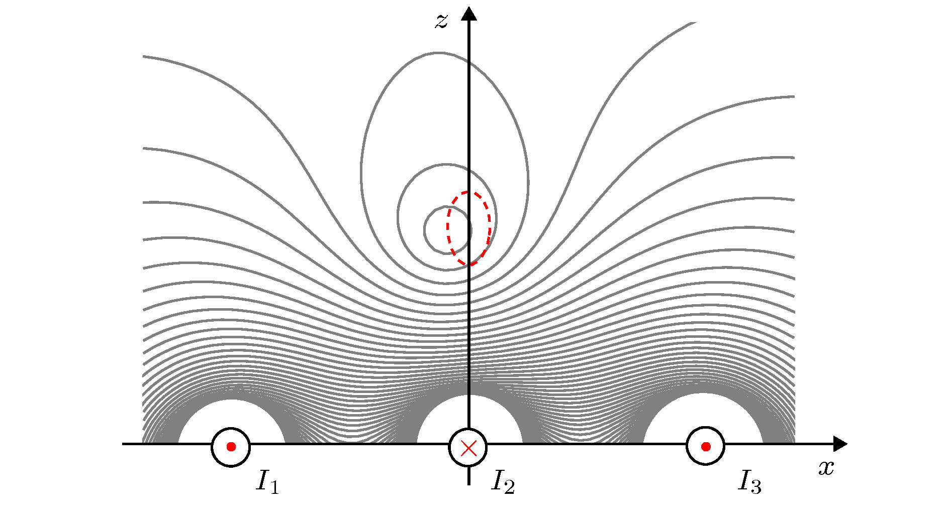
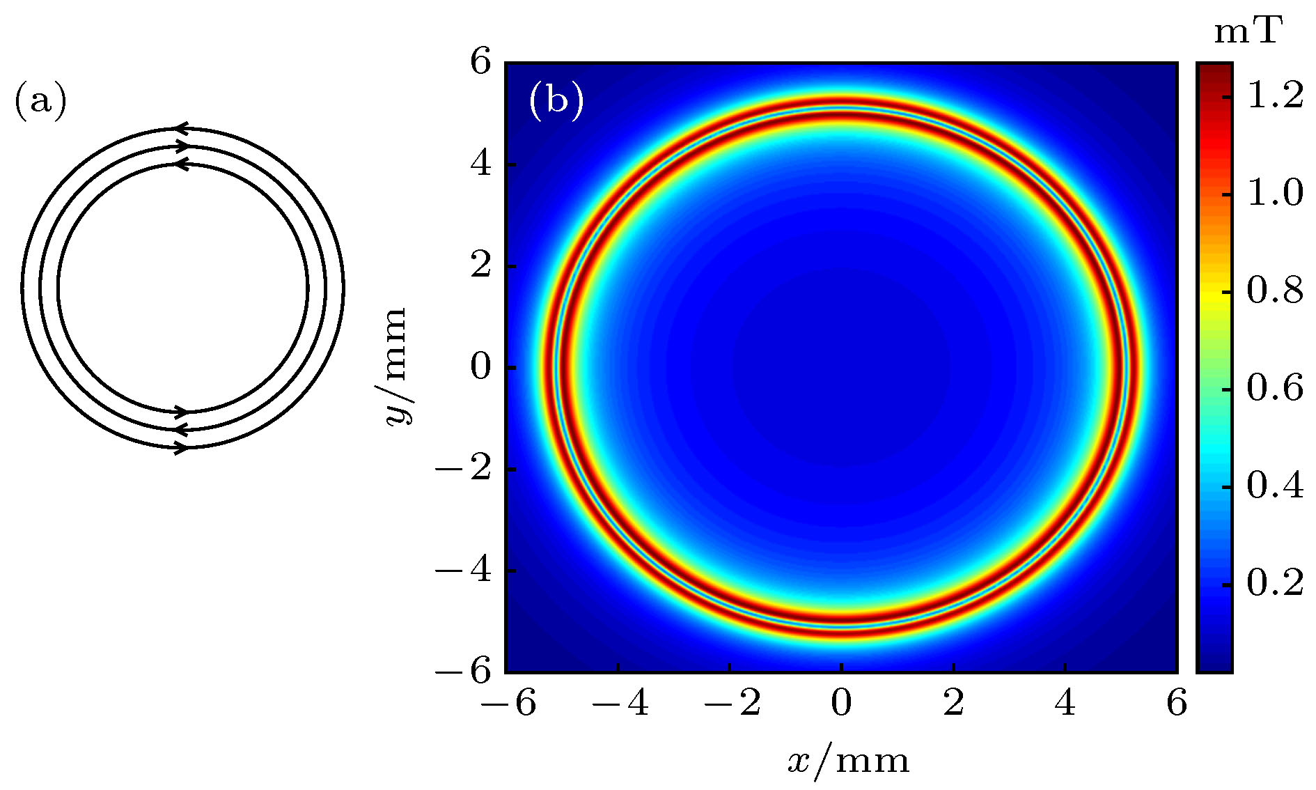
图 1 (a)理想三环线结构, 其中箭头表示电流方向; (b)理想环形磁导引的磁场分布示意图, 图中的蓝色圆环部分为环形磁导引
Fig. 1. (a) The ideal structure of the three concentric ring wires. The arrows represent the direction of currents; (b) The magnetic field intensity distribution of the ideal ring magnetic guide. The blue circle marks the ring magnetic guide.
图 2 三线阿基米德螺线环形磁导引的布线结构, 其中黑色实线、红色点划线和蓝色虚线分别表示三根不同的导线, 每根导线的引线端分别用1, 2, 3表示, 箭头表示电流方向, 阿基米德螺线起始半径
$a=5\ {\rm{mm}}$ , 相邻螺线的间距d = 0.1 mmFig. 2. Archimedean-spiral-based three wires structure of the ring waveguide. The black solid line, the red chain-dotted line and the blue dashed line denote three different wires respectively. The input and output ports of each wire are marked by 1, 2, 3 and the arrows represent the direction of currents. The initial radius of Archimedean spirals is
$a=5\ {\rm{mm}}$ and the distance between neighboring spirals is$d=0.1\ {\rm{mm}}$ .图 3 当调制频率
$\omega_{\rm b}=2{\text{π}}\times10\ {{\rm{kHz}}}$ , 电流位相$\phi=2{\text{π}}/3$ , 电流直流成分$I_{\rm i}=1\ {\rm{A}}$ 时, 导引中心的角向磁场起伏$\Delta\, B$ 与调制深度$I_{\rm j}/I_{\rm i}$ 的关系. 当$I_{\rm j}/I_{\rm i}=0.1$ 时, 环形磁导引中心磁场强度的起伏最小:$\Delta\, B\approx0.007\ {\rm{mT}}$ Fig. 3. The relation of the angular magnetic field intensity
$\Delta\, B$ of the guide center with the modulation depth$I_{\rm j}/I_{\rm i}$ when the modulation frequency is$\omega_{\rm b}=2{\text{π}}\times10\ {{\rm{kHz}}}$ , the current phase is$\phi=2{\text{π}}/3$ and the DC part of the currents is$I_{\rm i}=1\ {\rm{A}}$ . When the modulation depth is$I_{\rm j}/I_{\rm i}=0.1$ , the variation of the angular magnetic field intensity is the minimum:$\Delta\, B\approx0.007\ {\rm{mT}}$ .图 4 三线阿基米德螺线结构产生的环形磁导引在
$\theta={\text{π}}/2$ 截面上的磁场分布. 调制电流的直流成分$I_{\rm i}=1\ {\rm{A}}$ , 交流成分$I_{\rm j}=0.1\ {\rm{A}}$ , 调制频率$\omega_{\rm b}=2{\text{π}}\times10\ {\rm{kHz}}$ , 电流相位差$\phi=2{\text{π}}/3$ . 加载交流调制后, 磁场的瞬时极小值(磁场零点)沿红色虚线旋转, 旋转轨迹在水平和竖直方向上的变化幅度分别为$0.02\ {}$ 和$0.03\ {\rm{mm}}$ Fig. 4. The distribution of the magnetic field intensity in the
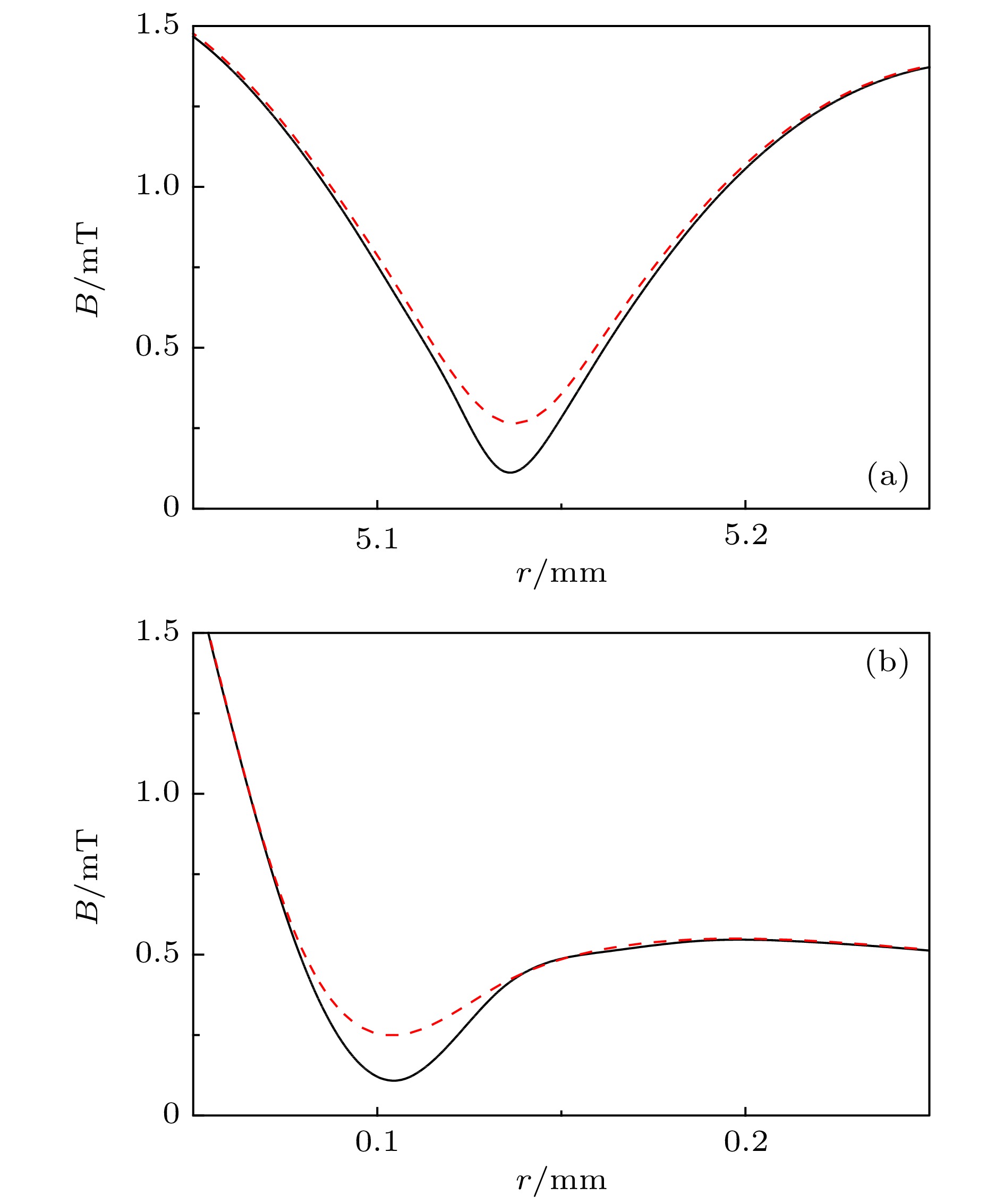
$\theta={\text{π}}/2$ cross section of the ring magnetic guide generated by the Archimedean-spiral-based three wires structure. The DC part and the AC part of the modulation currents are$I_{\rm i}=1\ {\rm{A}}$ and$I_{\rm j}=0.1\ {\rm{A}}$ , respectively. The modulation frequency is$\omega_{\rm b}=2{\text{π}}\times10\ {\rm{kHz}}$ . The current phase is$\phi=2{\text{π}}/3$ . After loading AC modulation, the minimum (zero point) of the magnetic field rotates along the red dashed line. The variation amplitude of the path along r and z direction are respectively$0.02\ $ and$0.03\ {\rm{mm}}$ .图 5 (a) 环形磁导引加载交流调制前(黑色实线)和加载交流调制后(红色虚线)在
$\theta={\text{π}}/2$ 截面上磁场在r方向上的分布; (b) 环形磁导引加载交流调制前(黑色实线)和加载交流调制后(红色虚线)在$\theta={\text{π}}/2$ 截面上磁场在z方向上的分布. 加载电流的直流成分$I_{\rm i}=1\ {\rm{A}}$ , 交流成分$I_{\rm j}=0.1\ {\rm{A}}$ , 调制频率$\omega_{\rm b}=2{\text{π}}\times10\ {\rm{kHz}}$ , 电流相位差$\phi=2{\text{π}}/3$ . 加载交流调制后, 截面上的磁场最小值由$0.12\ {\rm{mT}}$ 变为$0.26\ {\rm{mT}}$ Fig. 5. (a) The magnetic field distribution in the cross section with
$\theta={\text{π}}/2$ of the ring magnetic guide along r direction before (black solid line) and after (red dashed line) loading AC modulation; (b) The magnetic field distribution in the cross section with$\theta={\text{π}}/2$ of the ring magnetic guide along z direction before (black solid line) and after (red dashed line) loading AC modulation. The DC part and the AC part of the AC modulation currents are$I_{\rm i}=1\ {\rm{A}}$ and$I_{\rm j}=0.1\ {\rm{A}}$ , respectively. The modulation frequency is$\omega_{\rm b}=2{\text{π}}\times10\ {\rm{kHz}}$ . The current phase is$\phi=2{\text{π}}/3$ . After loading AC modulation, the minimum of the magnetic field intensity in the cross section changes from$0.12\ {\rm{mT}}$ to$0.26\ {\rm{mT}}$ .图 6 在三线阿基米德螺线上单独加载直流电流时的环形磁导引(虚线)和加载交流调制(实线)后导引中心的磁场强度随着角度
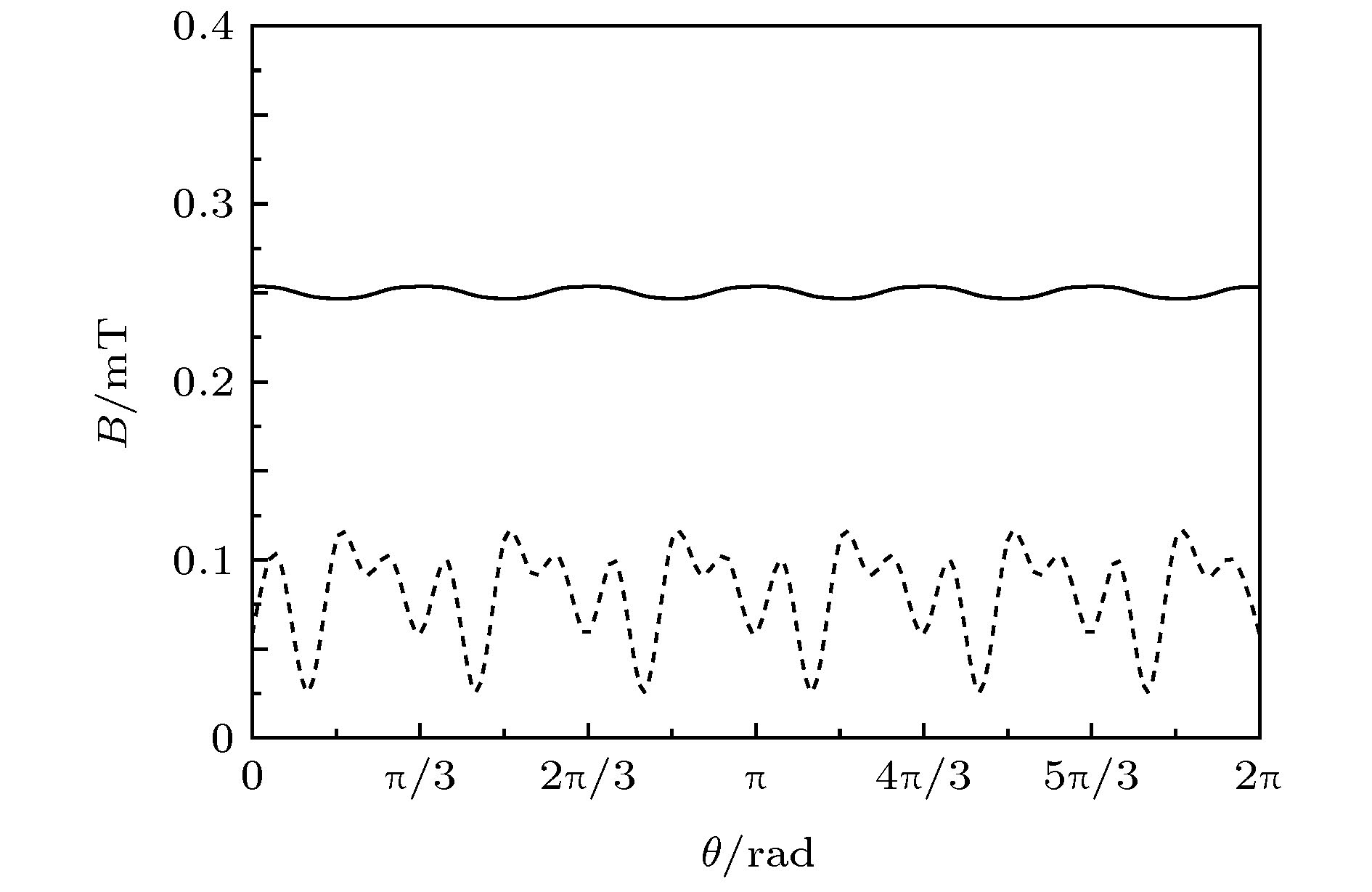
$\theta$ 的变化. 图中虚线情形: 三根导线上加载的直流电流分别为$I_1=1\ {\rm{A}}$ ,$I_2=-1\ {\rm{A}}$ ,$I_3=1\ {\rm{A}}$ , 导引中心的磁场强度的变化范围约为$0.025\, —\, 0.120\ {\rm{mT}}$ , 最大值和最小值之差为$0.095\ {\rm{mT}}$ . 图中实线情形: 三根导线上加载电流的直流成分$I_{\rm i}=1\ {\rm{A}}$ , 交流成分$I_{\rm j}=0.1\ {\rm{A}}$ , 调制频率$\omega_{\rm b}=2{\text{π}}\times10\ {\rm{kHz}}$ , 电流相位差$\phi=2{\text{π}}/3$ , 导引中心的磁场强度$B\approx0.25\ {\rm{mT}}$ , 磁场起伏$\Delta\, B\approx0.007\ {\rm{mT}}$ Fig. 6. The magnetic field intensity of the guide center versus azimuthal angle
$\theta$ for loading DC currents only (dashed line) and loading AC modulation (solid line), respectively. The dashed line: The DC currents applied to the three wires respectively are$I_1=1\ {\rm{A}}$ ,$I_2=-1\ {\rm{A}}$ ,$I_3=1\ {\rm{A}}$ . The variation of the magnetic field is about$0.025\, —\, 0.120\ {\rm{mT}}$ . The difference between the maximum and the minimum is$0.095\ {\rm{mT}}$ . The solid line: The DC part and the AC part of the AC modulation currents applied to the three wires are$I_{\rm i}=1\ {\rm{A}}$ and$I_{\rm j}=0.1\ {\rm{A}}$ , respectively. The modulation frequency is$\omega_{\rm b}=2{\text{π}}\times10\ {\rm{kHz}}$ . The current phase is$\phi=2{\text{π}}/3$ . The magnetic field intensity of the guide center is about$B\approx0.25\ {\rm{mT}}$ . The variation of the magnetic field is$\Delta\, B\approx0.007\ {\rm{mT}}$ .图 7 对三线阿基米德螺线加载交流调制. 加载调制电流的直流成分
$I_{\rm i}=1\ {\rm{A}}$ , 交流成分$I_{\rm j}=0.1\ {\rm{A}}$ , 调制频率$\omega_{\rm b}=2{\text{π}}\times10\ {\rm{kHz}}$ , 电流相位差$\phi=2{\text{π}}/3$ . (a) (b)分别为加载交流调制后导引中心空间位置在半径r方向和竖直z方向上的起伏变化, 起伏变化的幅度分别为$\Delta r=0.015\ {\rm{mm}}$ 和$\Delta z=0.005\ {\rm{mm}}$ Fig. 7. Applying AC modulation to the three-wires Archimedean spirals structure. The DC part and the AC part of the AC modulation currents are
$I_{\rm i}=1\ {\rm{A}}$ and$I_{\rm j}=0.1\ {\rm{A}}$ , respectively. The modulation frequency is$\omega_{\rm b}=2{\text{π}}\times10\ {\rm{kHz}}$ . The current phase is$\phi=2{\text{π}}/3$ . (a) and (b) are respectively the spatial position in r direction and z direction of the ring magnetic guide after loading AC modulation. The amplitudes of variation along r direction and z direction are$\Delta r=0.015\ {\rm{mm}}$ and$\Delta z=0.005\ {\rm{mm}}$ , respectively.图 8 加载交流调制后的三线阿基米德螺线环形磁导引在高度
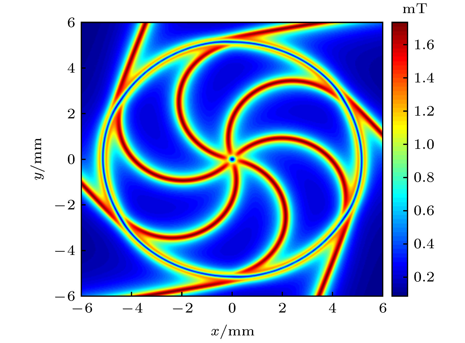
$z=115\ {\text{µ}}{\rm{m}}$ 处的磁场分布. 图中的蓝色圆环部分为环形磁导引, 导引中心的磁场强度约为$0.25\ {\rm{mT}}$ . 加载电流的直流成分$I_{\rm i}=1\ {\rm{A}}$ , 交流成分$I_{\rm j}=0.1\ {\rm{A}}$ , 调制频率$\omega_{\rm b}=2{\text{π}}\times10\ {\rm{kHz}}$ , 电流相位差$\phi=2{\text{π}}/3$ Fig. 8. The magnetic field intensity distribution of the three-wires Archimedean spirals structure of the ring magnetic guide at
$z=115\ {\text{µ}}{\rm{m}}$ when both DC and AC modulation are loaded. The blue circle marks the ring magnetic guide and the magnetic field intensity of the guide center is about$0.25\ {\rm{mT}}$ . The DC part and the AC part of the currents are$I_{\rm i}=1\ {\rm{A}}$ and$I_{\rm j}=0.1\ {\rm{A}}$ , respectively. The modulation frequency is$\omega_{\rm b}=2{\text{π}}\times10\ {\rm{kHz}}$ . The current phase is$\phi=2{\text{π}}/3$ . -
[1] Luo C Y, Huang J H, Zhang X D, Lee C H 2017 Phys. Rev. A 95 023608
 Google Scholar
[2] Che Y M, Yao F, Liang H B, Li G L, Wang X G 2018 Phys. Rev. A 98 053609
 Google Scholar
[3] Yao F, Che Y M, Su Y G, Liang H B, Pei J C, Wang X G 2019 Phys. Rev. A 99 052128
 Google Scholar
[4] Barrett B, Geiger R, Dutta I, Meunier M, Canuel B, Gauguet A, Bouyer P, Landragin A 2014 C. R. Phys. 15 875
 Google Scholar
[5] Deissler B, Hughes K J, Burke J H T, Sackett C A 2008 Phys. Rev. A 77 031604
 Google Scholar
[6] Yan H 2012 Appl. Phys. Lett. 101 194102
 Google Scholar
[7] Kreutzmann H, Poulsen U V, Lewenstein M, Dumke R, Ertmer W, Birkl G, Sanpera A 2004 Phys. Rev. Lett. 92 163201
 Google Scholar
[8] Wu S J, Su E, Prentiss M 2007 Phys. Rev. Lett. 99 173201
 Google Scholar
[9] Cronin A D, Schmiedmayer J, Pritchard D E 2009 Rev. Mod. Phys. 81 1051
 Google Scholar
[10] Wang J 2015 Chin. Phys. B 24 053702
 Google Scholar
[11] Geiger R, Menoret V, Stern G, Zahzam N, Cheinet P, Battelier B, Villing A, Moron F, Lours M, Bidel Y, Bresson A, Landragin A, Bouyer P 2011 Nat. Commun. 2 474
 Google Scholar
[12] Sauer J A, Barrett M D, Chapman M S 2001 Phys. Rev. Lett. 87 270401
 Google Scholar
[13] Wu S J, Rooijakkers W, Striehl P, Prentiss M 2004 Phys. Rev. A 70 013409
 Google Scholar
[14] Gupta S, Murch K W, Moore K L, Purdy T P, Stamper-Kurn D M 2005 Phys. Rev. Lett. 95 143201
 Google Scholar
[15] Arnold A S, Garvie C S, Riis E 2006 Phys. Rev. A 73 041606
 Google Scholar
[16] Baker P M, Stickney J A, Squires M B, Scoville J A, Carlson E J, Buchwald W R, Miller S M 2009 Phys. Rev. A 80 063615
 Google Scholar
[17] Pritchard J D, Dinkelaker A N, Arnold A S, Griffin P F, Riis E 2012 New J. Phys. 14 103047
 Google Scholar
[18] West A D, Wade C G, Weatherill K J, Hughes I G 2012 Appl. Phys. Lett. 101 023115
 Google Scholar
[19] Vangeleyn M, Garraway B M, Perrin H, Arnold A S 2014 J. Phys. B: At. Mol. Opt. Phys. 47 071001
 Google Scholar
[20] Sinuco-Leon G A, Burrows K A, Arnold A S, Garraway B M 2014 Nat. Commun. 5 5289
 Google Scholar
[21] Jiang X J, Li X L, Xu X P, Zhang H C, Wang Y Z 2015 Chin. Phys. Lett. 32 020301
 Google Scholar
[22] Jiang X J, Li X L, Zhang H C, Wang Y Z 2016 Chin. Opt. Lett. 14 070201
 Google Scholar
[23] 程俊, 张敬芳, 许忻平, 蒋小军, 李晓林, 张海潮, 王育竹 2016 65 060302
 Google Scholar
Cheng J, Zhang J F, Xu X P, Jiang X J, Li X L, Zhang H C, Wang Y Z 2016 Acta Phys. Sin. 65 060302
 Google Scholar
[24] Folman R, Kruger P, Cassettari D, Hessmo B, Maier T, Schmiedmayer J 2000 Phys. Rev. Lett. 84 4749
 Google Scholar
[25] Lovecchio C, Cherukattil S, Cilenti B, Herrera I, Cataliotti F S, Montangero S, Calarco T, Caruso F 2015 New J. Phys. 17 093024
 Google Scholar
[26] Petrich W, Anderson M H, Ensher J R, Cornell E A 1995 Phys. Rev. Lett. 74 3352
 Google Scholar
[27] Feenstra L, Andersson L M, Schmiedmayer J 2004 Gen. Relativ. Gravitation. 36 2317
 Google Scholar
[28] Arnold A S 2004 J. Phys. B: At. Mol. Opt. Phys. 37 L29
 Google Scholar
计量
- 文章访问数: 10169
- PDF下载量: 169
- 被引次数: 0


 下载:
下载:


